Control robots created with LEGO® Mindstorms® NXT Brick using the Wolfram Language (Mathematica)
Download the article as a Mathematica document (NB) , CDF file or PDF .
NXT is a general purpose processor that is used to control motors and sensors; It is ideal for creating autonomous robots. It can also communicate with more complex software on the computer via Bluetooth. In this article, we will show how to properly interact with the NXT through the Wolfram Language ( Mathematica ), sending the correct signals. We will also introduce a package that manages all interactions between functions. These functions can be used in conjunction with dynamic cells to display the status of the robot and control its motor.
Introduction
Robots are ideal targets for testing cognitive theories, such as learning, adaptation, and also for classifying environmental impacts. A key element of most robots is the central processor, which receives media data through sensors and acts on the environment with the help of motors. To this end, in 2006, LEGO introduced a new programmable designer - LEGO MINDSTORMS NXT. This designer, equipped with four sensors and three motors, has 256 KB of flash memory for storing data. It can run programs compiled specifically for this constructor (files with the .rxe extension compiled by LEGO LabVIEW or third-party compilers, such as NBC or NXC). The versatility and low cost of this designer make it an ideal object for projects to develop robots.
NXT is well suited for the development of autonomous robots, including intelligence. You can also explore learning algorithms; for example, you can find more optimal ways to solve the problem of finding a way out of the maze, rather than the usual trial and error method. Finally, NXT can also be used to study social cognitive models in which multiple robots must interact in order to increase group survival.
')
This article shows how to control the designer via Bluetooth. We will also introduce the Math4NXT package, which facilitates a number of tasks. Used in conjunction with the built-in Dynamic function in Mathematica , the LEGO robot control becomes very simple.
Creating a communication line
The first time you run NXT, use Bluetooth on your computer to find it and create a connection. As for the very first use, you will need to enter a password on the constructor (by default - “1234 ″) and the computer. Then you will need to select the “Dev” service available on the constructor. Thus, the COM port is allocated as a communication link between the computer and the designer. The COM port name is set as a variable (for example, COM11), however, it remains constant for a specific computer-NXT pair (for more detailed instructions on pairing, see [1]). Once you have specified a specific COM port, you will no longer need to repeat this process.
The NXT designer has an operating system (firmware), which immediately processes requests received from the COM port. He does this even if the program is currently running on the constructor. These commands in the LEGO documentation [2] are called direct . Direct commands include file operations, motor control, setting up sensors and reading data from them, interaction between different designers. Commands are transmitted via the COM port by means of messages representing a sequence of bytes (numbers from 0 to 255). Some commands imply a response from the constructor, which is also sent as a message. Before each message, information is sent about the length of this message, to which 2 bytes are allocated. Thus, the management of the NXT constructor is the sending of certain bytes in a certain order through the serial port.
In order to use the serial COM port, you should use a package for Mathematica called SerialIO [3]. This package consists of two parts. The first is an executable program designed for your computer and operating system. SerialIO presents such programs for Linux, Windows (32-bit and 64-bit), as well as for OS X. The second part contains Mathematica functions that can be used in your project. It includes the SerialOpen and SerialClose commands for opening and closing the communication channel on this COM port, and SerialWrite and SerialRead write or read data from the COM port. The figure below shows the different levels through which information flows during communication between the NXT and the computer.
Figure 1. Software architecture communicating with the NXT and the computer. The last three windows on the right represent Mathematica programs, and the other two are issued by the Math4NXT package, which will be discussed later.
Download the SerialIO package from the Wolfram Library Archive and install it in the folder of your choice (best of all in AddOns Mathematica , which is in the ExtraPackages folder). For more convenience, you can place your working folder at this address, as a result of which MathLink-compatible programs will be automatically saved there.
Next, download the package via Needs .
If the command is successful, you can see the SerialO process running on your computer in the background. The following command opens the COM port and establishes a communication channel with the constructor (it must be enabled).
If you have a NXT constructor and you want to calculate the code cells that are presented in this article, then you need to select a cell while holding the Alt key, so all cells will be selected. Next, from the Mathematica main menu, select Cell Cell Properties Evaluatable. Without the NXT connected, executing these commands will return an error message and an uncalculated cell.
To make sure the connection is open, look at the display on the constructor, which is in the upper left corner. If you see
Exiting Mathematica (or stopping the kernel) closes the COM port and terminates the SerialO process, which runs in the background.
Sending a message and receiving a reply
The SerialIO package was made to send text via the COM port (or individual characters / lines of text). However, with regards to managing the NXT, it makes more sense to send the numbers directly. Therefore, we need to convert the numbers to the corresponding characters in the ASCII code before we send them. This is a bit inconvenient, and we will propose a more accurate solution later.
The message always starts with a byte that indicates whether the NXT should respond to it. It’s more convenient for anyone, but many commands sent to the constructor return only a status byte (0 - successful execution, otherwise - an error message). In the case of a response message in the form of a status byte, the response is rather useless. To request a response, the first byte must be 0; 128 means the NXT should not respond.
The second byte of the message is always the command number. All this is presented in the documentation of the LEGO Group [2]. Subsequent bytes depend on the command sent.
For example, a request to NXT to play a sound is set by the direct PlayTone command. The number of this command is 3. Then two parameters must be set: the tone frequency (a number from 200 to 14000) and the duration of the tones (in milliseconds, a number from 0 to 65535). These two parameters are encoded as UWORD (unsigned word - WORD), that is, more than two bytes are allocated, the least significant byte is set first. For convenience, we will write the conversion function toUWORD .
Thus, a tone frequency of 480 Hz and a duration of two seconds correspond to the following sequence of bytes.
The whole message would look like this.
Before the message itself, its length must be indicated, which can be obtained by the following command.
We combine the two parts to get the complete message and get a list of characters corresponding to their numbers (such characters may not be viewable on your computer) in this line of code.
Let's send these characters to the NXT designer one by one.
Now you can hear the beep. Since we requested an answer (the first byte was zero), we need to read it.
Again, the answer consists of text (the characters may not be viewable). Let's convert them to a list of numbers.
The bytes are returned in the following order: the length of the returned message, encoded in more than two bytes in UWORD (in this case, 3, 0 means the length of the message is 3 characters), the second byte indicates that this is a response message; the third byte indicates the number of the command that issued the response (in this case, the Playtone command) and, finally, the status of the command (where 0 indicates success). PlayTone does not return other information; Some direct commands may return more complex messages.
As an example, we send the GetBatteryLevel command. This command is number 11 and does not require any parameters / additional information. If a response is requested (but it is meaningless to send this command and not request an answer), it returns the command status (0 for success), followed by two bytes indicating the battery voltage on the NXT in millivolts. To decipher the voltage, let's create another conversion function - fromUWORD .
Let's collect the whole message, combine it with its length, convert it into a list of characters and send them.

Now let's read the answer and convert it to numbers.
The first two bytes indicate the length of the response (5 bytes); 2 and 11 show that this is a response to the GetBatteryLevel command; 0 indicates that the command was successful; and finally, 247 and 27 show the battery voltage, which we convert to a number with the fromUWORD command described above.
Thus, the batteries have a voltage of 7.16 volts, which is much lower than the expected 9 volts for fresh batteries.
SerialWrite override to send whole numbers or lists of them
Since it is more convenient to represent numbers, rather than characters, that are sent to the constructor, we expand the SerialWrite command contained in the SerialIO package to be able to send both individual integers from 0 to 255 (bytes) and their lists.
With this extension, the entire message (which consists of bytes) can be transmitted by one call to SerialWrite . For example, the following instructions reassemble the PlayTone team (this time without an answer).

The entire message is sent by calling one command.
Direct commands represented in Math4NXT
The above shows how a command can be sent to the NXT constructor, and its response read. Then, it’s just a question of assembling the message in the correct order and with the right information, and, if necessary, reading the answer and its interpretation. For these purposes, the documentation provided by the LEGO Group (especially Appendix 2 in [2]) is fairly complete.
For greater simplicity, we encoded all the direct commands in a package called Math4NXT . You should first get the Math4NXT package. Since it uses the SerialIO package in the background, also install it in the directory where Mathematica searches (for example, FileNameJoin [{$ InstallationDirectory, "AddOns", "ExtraPackages", "SerialIO"}] ). Then load Math4NXT with the following command.
Since we placed the Math4NXT package not in one of the folders Mathematica searches for, we need to set the path using the Needs command. Then open the serial port (if it has not already been done), as shown earlier.
All direct commands begin with the letters NXT . Therefore, the command to read the battery level in the package will be called NXTGetBatteryLevel .
By default, the command returns a response using named strings (for example, “Status” ). You can extract some of the information in the usual way.
This format can be changed, for example, to raw (that is, to output in bytes, as in the two previous sections), using the ResultFormat option.
On the other hand, the transmitted and received bytes can be displayed in a separate window using the option
This option opens a message box .

Figure 2. A message window opens automatically when the option
All direct commands are available.

Expansion of direct commands
Direct teams have many limitations. Firstly, due to the nature of the COM port, the message can not be longer than 253 bytes. This is a big limitation when working with files that can be much larger. In addition, LEGO sensors work very differently; Some sensors are passive, do not require power, while others are active, and still others are programmable - like I2C sensors. To use the commands uniformly and avoid length restrictions, we set higher-level commands within which these problems are solved.
The names of all these commands begin with M4N .
One example is the M4NFileNames command that lists all the files present on the constructor (optionally with file size).

This command works by calling the direct commands NXTFindFirst (command number 134), NXTFindNext (135), and NXTClose (132), using the algorithm given in Program 1. To see several calls to the NXT commands, use the option
res=NXTFindFirst[mybrick,"*.*"]; While [("Status"/.res)=0, res=NXTFindNext[mybrick,"Handle"/.res] ] NXTClose[mybrick]; Program 1. M4NFileNames uses a general algorithm to retrieve all the file names present on the NXT. This algorithm does not show how to collect file names (contained as bytes in res ) into a list.
Similarly, to facilitate the use of sensors, there is a command that transmits a message to Mathematica about the types of sensors connected. The reading from the sensor is subsequently made according to its type. To set the sensor type, use the M4NSetSensor .
After that, reading from the sensor is performed by the universal command M4NReadSensor . To match the style of direct commands, the first sensor is placed on port 0 of the NXT input.
The result is presented either as 1 for the “pressed” state, or 0 as for the “unpressed” state. This command works the same regardless of the type of sensor connected. Therefore, if you connect the ultrasonic sensor to the third input, you can run the following two commands.
An ultrasonic sensor is a sophisticated sensor designed to detect the distance to obstacles in front of it (in cm). It is equipped with a microprocessor that works on the I2C protocol. It must first be turned on, and after downloading it, you can start reading data from it. Using the option
Work with motors
Another limitation of direct NXT firmware commands concerns engine control. New LEGO engines contain built-in rev counters that track the amount of rotational motion. However, a direct command can only stop the engine when it reaches a certain number of degrees passed, after which the motor changes its direction of rotation.
Motor PID controller is a more efficient way to control rotation. It sets the number of degrees and adjusts the engine power so that it slows down when the goal is almost reached (using the integral and the derivative; see [4, 5]).
The authors [5] developed a PID controller for the NXT. This controller is on the NXT; the computer sends the specified motion, after which the controller takes control of the engine, adjusting the force until the number of degrees of rotation is reached. The program of the controller is called MotorControl22.rxe , for version 2.2.
Take the program MotorControl22.rxe and send it to the constructor. To do this, import the contents of the file into Mathematica and upload it to NXT. After installation (this step may take several minutes when transferred via Bluetooth - the file weighs 37 kilobytes) you can start the controller. Here are the commands to accomplish this; The first part verifies that the file is not yet on the constructor.

Finally, via M4NSetMotor, tell your program what types of engines you have and which port they are connected to.
By the way, M4NSetMotor loads MotorControl22.rxe, if it is not present on the constructor and starts this program, if it is not already running. Therefore, you can not worry about these details and can only rely on M4NSetMotor .
Now that the controller is up and running, you can send instructions to it using commands related to motors.

M4NRunMotor , M4NStopMotor and M4NBrakeMotor can be used both on conventional engines and on engines with a rev counter (tachometer). However, M4NRunMotorFor can only be used with motors equipped with a tachometer and a PID controller. If the engine is controlled by a PID controller, then you should not send any other instructions. Therefore, M4NRunMotorFreeQ can be used to test the controller.
The following command set starts two motors.
You can stop the motors using two different modes ( M4NBrakeMotor blocks the engine, while M4NStopMotor stops feeding the engine).
The following commands verify that the MOTORA motor is free — before driving, while driving (10 full turns) and six seconds after the movement began.
Robot Setup
At the program level, the robot has a specific configuration that determines which sensors are connected to the input and which motors are available at the output. Earlier, we showed two commands that can be used to identify sensors and motors.
We have created a generic M4NInitialize command, the goal of which is to install all these elements in one command. In addition, it can also be used to set the volume level and assign a name to the designer (if you have a lot of them, it would be nice to rename it by the name of the COM port to which they are connected).
In addition, M4NInitialize checks whether the firmware version on the NXT is compatible with this package and that the battery has a sufficient charge level (otherwise it returns a warning). You can also set the path to the folder containing the MotorControl22.rxe controller using the MotorControlPath option, in case it is still not on the NXT.
Dynamic robot control
M4N and NXT commands can be used dynamically. For example, to get the current state of touch sensors, the following steps should be performed.
First, initialize the sensors using M4NInitialize or M4NSetSensor .
The ShowSensor function creates a panel with On and Off elements, which are set depending on the sensor value. This feature uses some options for convenience only.
Then, we can use ShowSensor four times in a row to get a string with indicators.
The UpdateInterval option determines how long to communicate with the sensors.
As a final example, we will create a joystick that controls two motors. Motor rotation speed (adjusted by the MotorPower option) depends on the position of the joystick (vertical axis). In addition, the motors move synchronously if the position of the joystick is centered on the horizontal axis.
First, we define an advanced ClickPane function that works with more events than the regular ClickPane function.
We must remember to initialize the motors (so that the PID controller is on).
That's all. The following example displays a panel with a red dot (top of the joystick). Thus, we constantly set the engine power so that it is proportional to the position of the joystick. In addition, if the joystick is released, it returns to the center with an exponential function represented by the variable mult . Finally, if you click on the panel anywhere, the joystick will instantly return to the center with a beep.
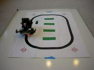
Robot moving along a given trajectory
To illustrate a simple example of an autonomous robot, we will create a robot moving along a specific path. The purpose of this robot is to follow the edge of a certain line. The line should be dark on a light background (or vice versa); border contrast is an important factor. To achieve this, you will need a robot equipped with a light sensor at the front (see, for example, the assembly instructions given on page 33 of the MINDSTORMS training brochure [2]).
For this project, we will need a light sensor and two motors, which we initialized.
At the first stage, we must calibrate the sensor so that the readings on the light and dark surfaces are set. Use the code below to get 100 readings when the robot moves on a light surface.
Then use this code when moving the robot on a dark surface.
The average of the above two values is a critical value. If the robot, which follows the left edge of the dark line, observes a lighter area than the average value, we need it to go to the right (and vice versa).
The next short program moves the robot at a moderate speed (the variable basespeed is set to 20) and adjusts the base speed according to the difference between the current reading and the average value.

The mult constant is used to control the steering coefficient. Larger values cause the robot to make sudden changes in direction. This value should be small for smooth movement. However, if there are sharp turns on the trajectory, the small multiplier does not allow the robot to turn a sufficient angle to find the edge again. The findings will present some details.
Technical limitations
There are several direct commands that we decided not to implement in this package. They are related to rebooting the NXT, changing its firmware, erasing the flash memory, and performing a reset. In essence, these commands destroy the robot.
With the M4N and NXT commands, the robot can be controlled very efficiently and easily. However, the COM port is not very fast. It is important to note that each switch in the direction of transmission of the port signal takes 6 ms. This is the reason why answers should be avoided if they are not really necessary. In some applications, these delays may be so important that the program must be moved to the constructor in whole or in part. The MotorControl22.rxe PID controller is an example in which a program is distributed between two machines: the computer sets the necessary movements, and the designer executes the millisecond solutions within the millisecond to achieve the goal.
findings
There is one new theory in cognitive science - the theory of incarnations. She argues that the cognitive system must be in interactive communication with the outside world in order to develop a meaningful view of the world. This view is contrary to the classical view of artificial intelligence (AI), which states that cognitive agents manipulate features or symbols that may not be related to aspects of the external world. Therefore, from the point of view of AI, sensors and actuators do not depend on cognitive functions and can be built separately. This view is valid when we develop cognitive systems in the virtual world (for example, based on computer modeling). However, when robots get physical incarnation, we see how difficult it is to hold this position.
A simple program of following the trajectory shows it. In a virtual environment, the robot following the trajectory can operate at full speed, and the turns can be sharp, because there is no inertia and the risk that the robot will fall. When a robot gets physical incarnation, these aspects become very serious problems. Of course, the programmer adapts the program to take into account these risks (reduction in speed and decrease in the gain factor). In addition, data on bright and dark areas are calibrated by the programmer in a very simple way. However, if the ambient light changes, calibration should be done again. In addition, as mentioned earlier, if the mult multiplier is too small, the robot may not be able to move fast enough around a sharp curve. Finally, the robot following the trajectory uses wheels. If he used his legs instead, the flexibility and limitations of the muscles would take effect.
All the above problems can be considered at worst as inconveniences, and at best as challenges for the programmer. However, the simplest animals are immune to all these problems. The theory of incarnations asserts that organisms have created the proper ideas about the world, interacting with it, and that these ideas have become reliable in relation to all possible sources of malfunction. Representations and algorithms specified by the programmer, on the other hand, may not meet the requirements of the real world, no matter how simple and elegant they may be.
NXT is a simple but complete platform for testing robots in real life. In combination with the computing power of the Mathematica system, it is easy to develop adaptive algorithms, such as neural networks, and to observe what ideas the robot has about the world. It remains to be seen what the simplest adaptive program of the robot looks like, which follows a predetermined path.
Thanks
The author would like to thank Vincent Brault, Dominic Langlois and Sylvain Chartier from the CONEC laboratory (University of Ottawa) for their help in developing the Math4NXT package.
References
[1] MathWorks. “Set Up a Bluetooth Connection.” (Feb 4, 2013) www.mathworks.com/help/simulink/ug/bluetooth-communications.html .
[2] The LEGO Group. “LEGO MINDSTORMS NXT Bluetooth Developer Kit.” (Jan 7, 2013) mindstorms.LEGO.com/en-us/support/files/default.aspx .
[3] R. Raguet-Schofield. “SerialIO.” Wolfram Library Archive. (Jan 7, 2013) library.wolfram.com/infocenter/MathSource/5726 .
[4] J. Sluka. “A PID Controller For LEGO MINDSTORMS Robots.” (Jan 7, 2013) www.inpharmix.com/jps/PID_Controller_For _Lego _Mindstorms _Robots.html .
[5] Institute of Imaging & Computer Vision. “RWTH — MINDSTORMS NXT Toolbox.” (Jan 7, 2013) www.mindstorms.rwth-aachen.de/trac/wiki/MotorControl .
D. Cousineau, “Controlling Robots Built with the LEGO MINDSTORMS NXT Brick,” The Mathematica Journal , 2013. dx.doi.org/doi:10.3888/tmj.15-3.
about the author
Denis Cousineau is a professor of cognitive psychology at the University of Ottawa. He conducts research in the field of artificial intelligence and the process of classification of objects by man.
Contact details: École de psychologie, Université d'Ottawa, 136, rue Jean-Jacques Lussier, Ottawa (ON), K1N 6N5, CANADA, e-mail: Denis.Cousineau@UOttawa.ca
Source: https://habr.com/ru/post/256345/
All Articles