The story of creating another robot. Part Two, "it's alive!"
I continue a series of publications on the creation of a simple wheeled robot on an ATmega16A microcontroller.
In the second part of my publication, I will describe the process of creating and assembling my robot. Let's start with the manufacture of a printed circuit board and finish the video of the first steps (or, more correctly, scrolling the wheels) of our device. I will also pay attention to the first experience of PC programming in Qt, namely the creation of a control program and data exchange with the robot via Bluetooth.
If you want, you can familiarize yourself with the first publication and find out how it all began, but I’ll ask everyone else for a cat.
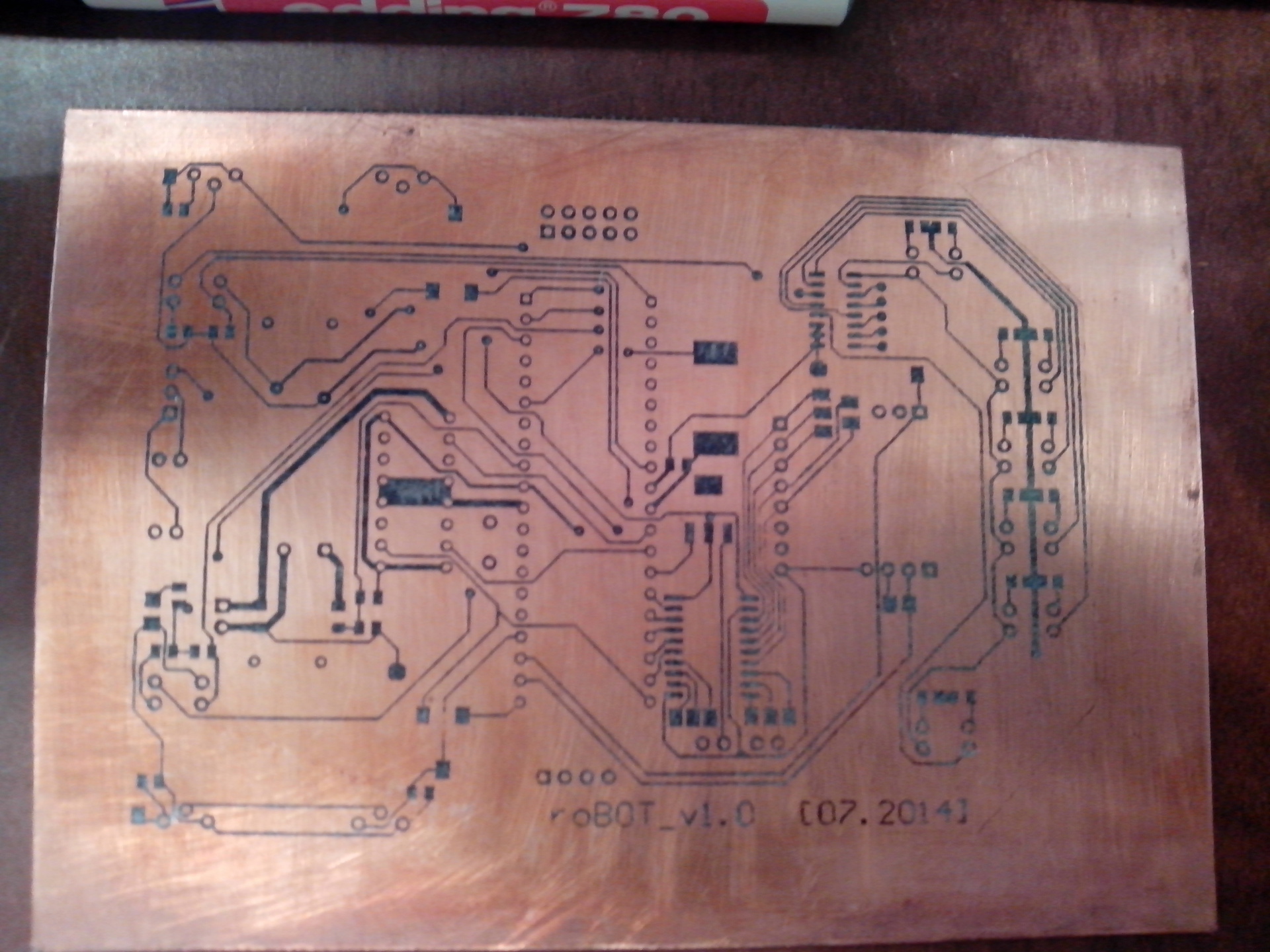
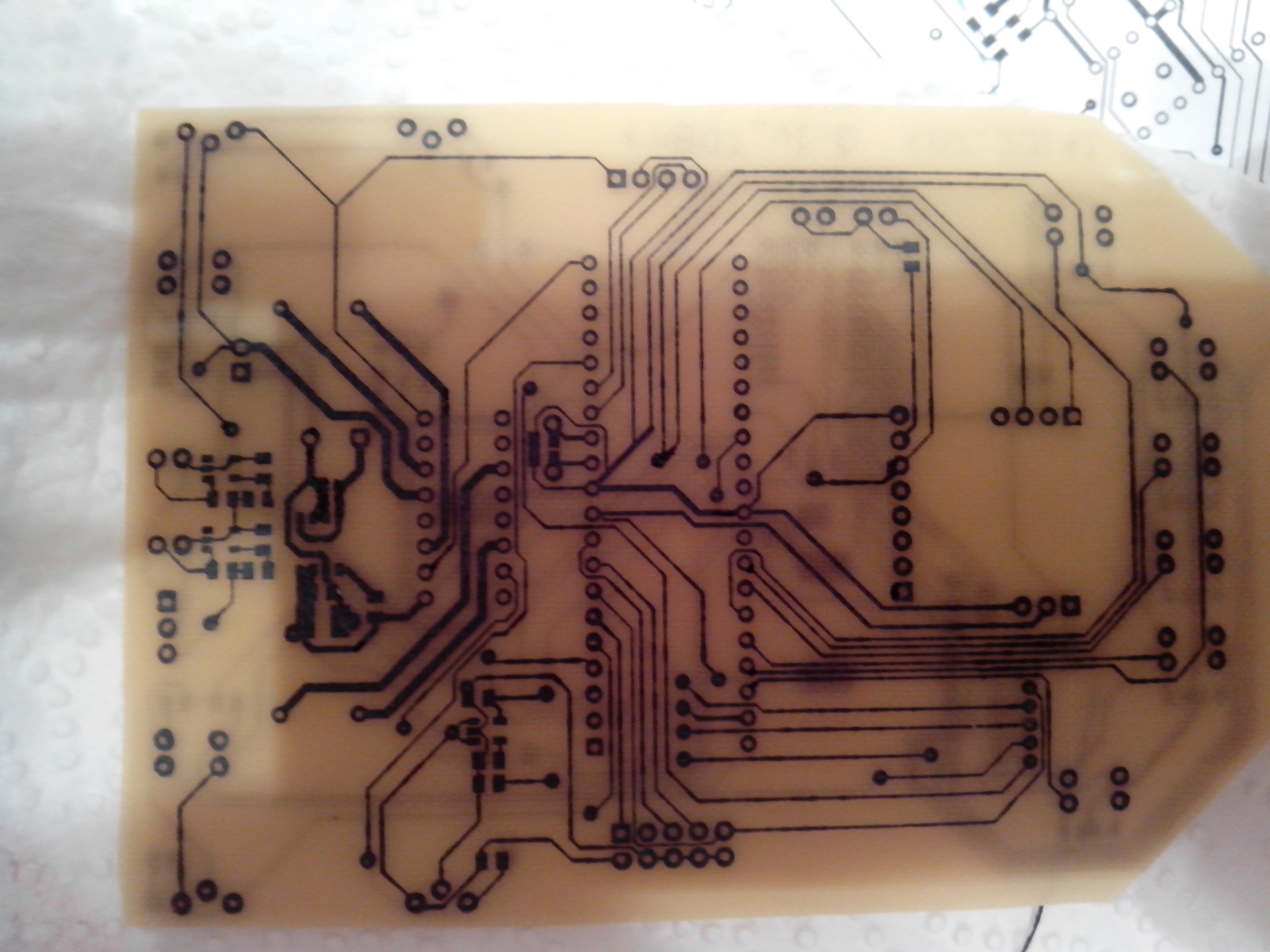
The last part ended with the fact that there was a ready layout of the printed circuit board in front of us, which means that it’s time to create and transfer our idea from the electronic version to the real tangible world, doesn’t that desire lie in the mind of every radio amateur, engineer, inventor ?! I only had 1mm textolite on my hands, so without thinking twice I began the process of transferring the track pattern to the board using standard LUT.
I apologize for the quality of the photos, but I have a cheap phone ...
')
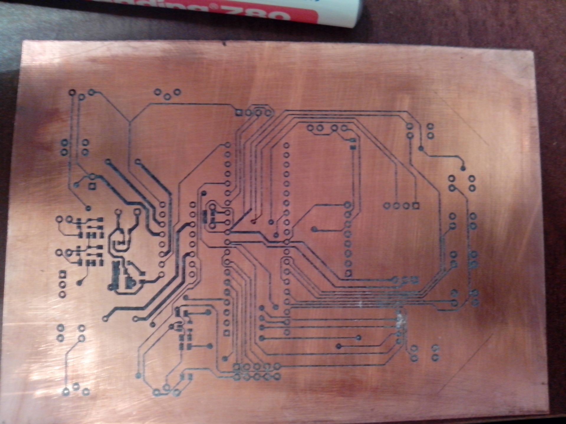
The next step was etching! I tried a new method of etching with hydrogen peroxide and citric acid, which is certainly safe and very cheap, but it seemed to me too sensitive to the proportions of the components. After an hour of magical manipulation of the container with a solution, the process went with decent strength (it is worth saying that it was possible to change the board template and then everything would have worn out much faster).
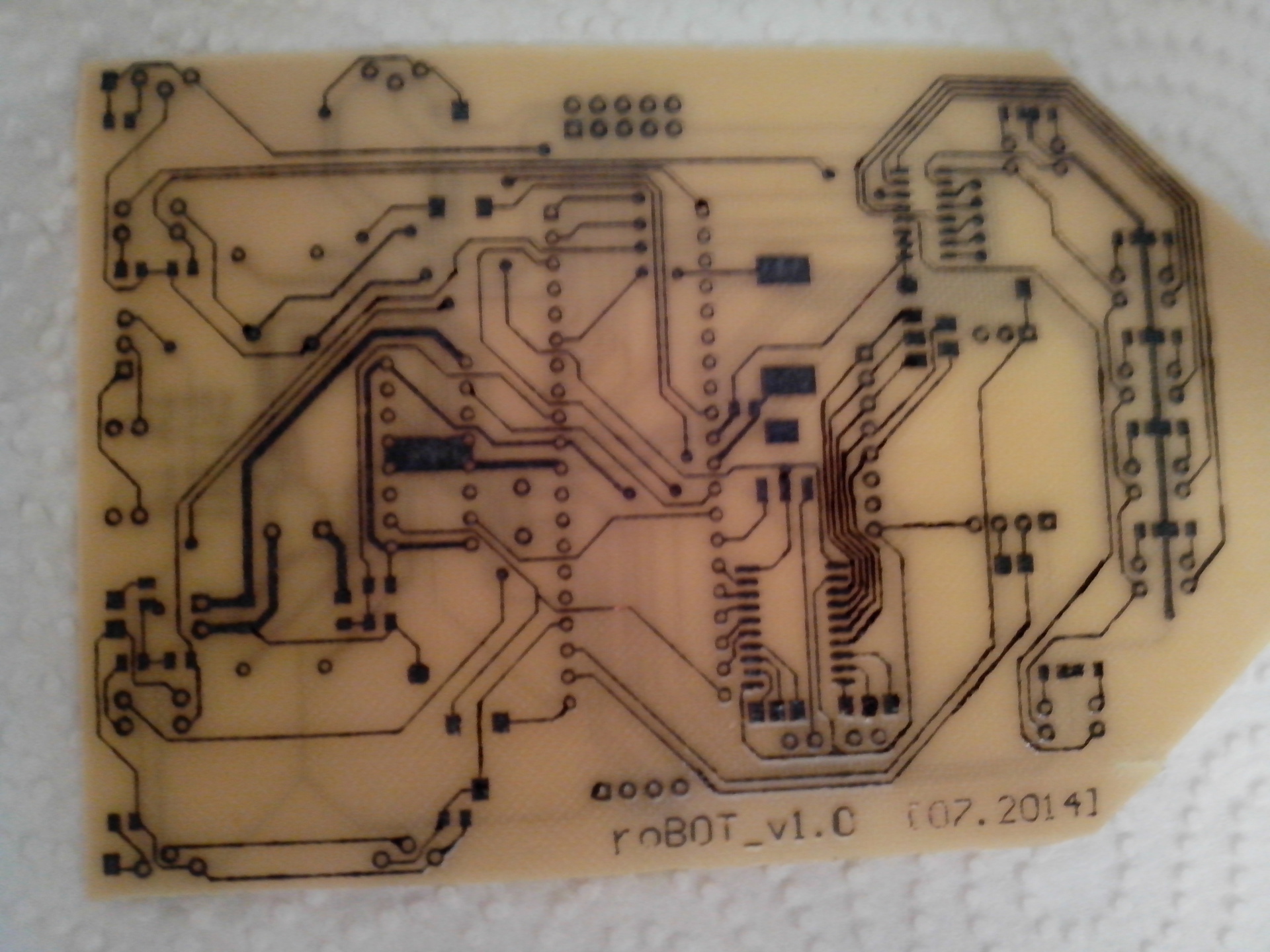
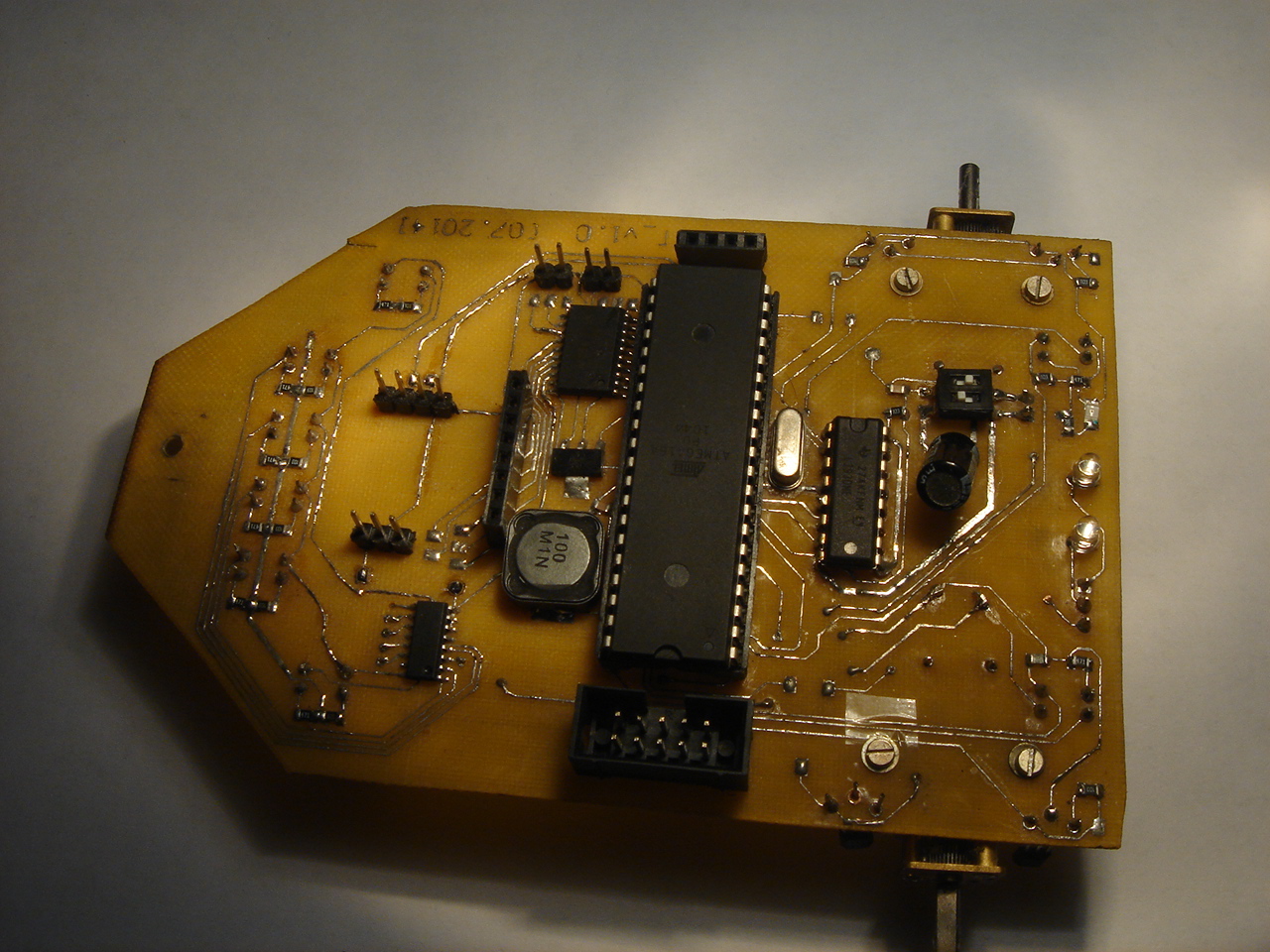
80-90% of the tracks on the board turned out well, but because Most of the tracks were 0.2mm, mordants caught, which I removed with solder and thin conductors, thanks to them I made vias. In general, the whole process of soldering took 3 pm.
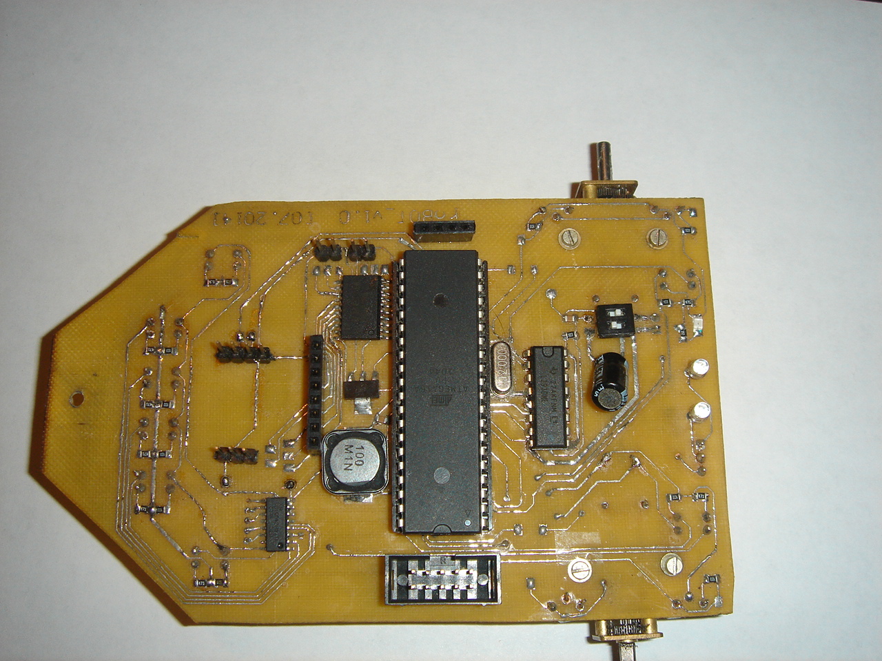
Motors had to be transferred to the bottom of the board, because I realized that I needed the maximum gap between the board and the surface on which I would need to drive, but still the robot turned out to be low-lying.
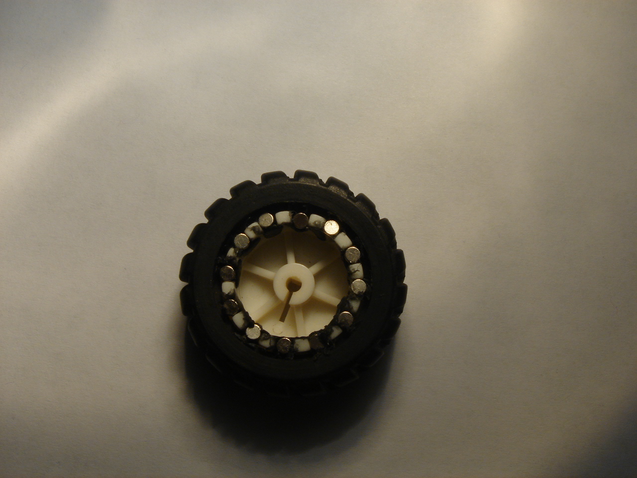
And since we remembered the motors, we also recall the idea with the encoder, since the magnets I ordered were literally half a millimeter in diameter less than the grooves in the wheel, they had to be fixed there somehow, but as we know everything ingenious is simple - I just took them and drove them there, filling the bay with a glue gun is not very aesthetic, but quickly and practically. The main thing is not to confuse the polarity, otherwise there will be shoals with accuracy, but it is already small - 12 magnets per wheel, i.e. 6 actuations per turn, and with a wheel diameter of 43mm, we get approximately 22mm of the distance traveled by the wheel in one operation.
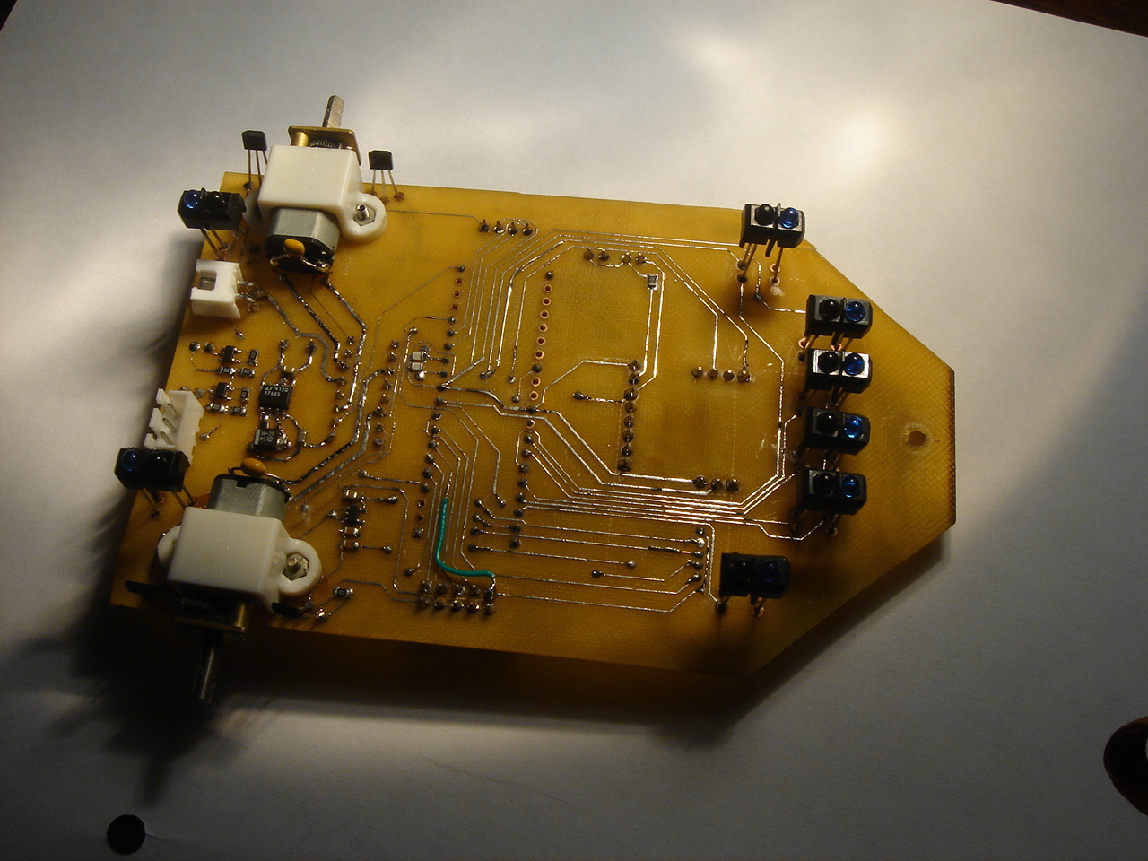
On the board, in turn, with a small spacing in height, put the Hall sensors to understand which way we are going.

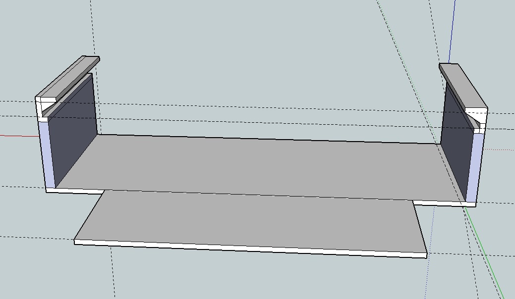
To attach the battery, serva and ultrasonic rangefinder were printed on a 3D printer, the simplest parts.
Battery holder
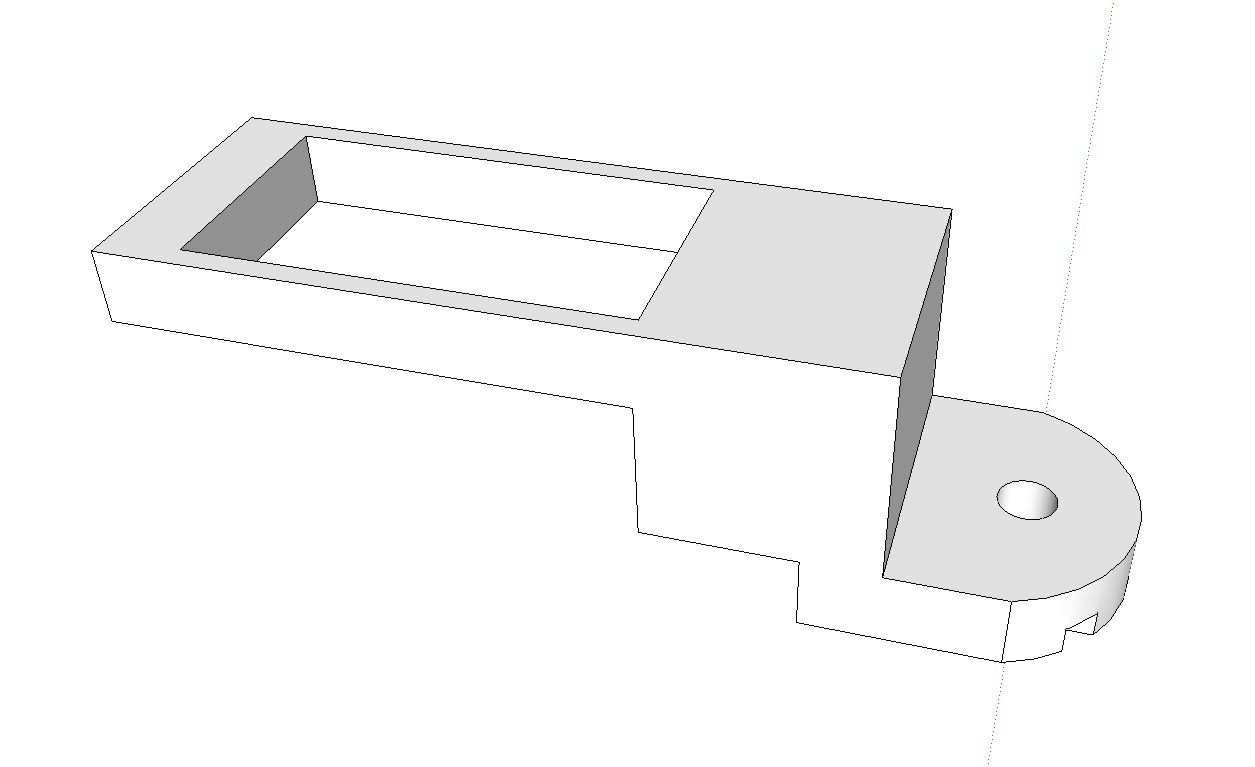
Servo holder.
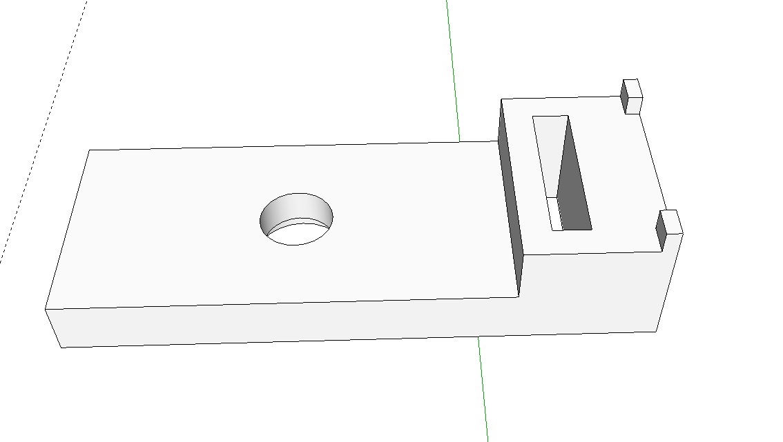
UZ range finder holder.
A bit of fine-tuning of the parts with a file and everything fell into place, in the end, the robot turned out like this.
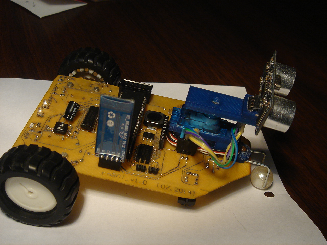
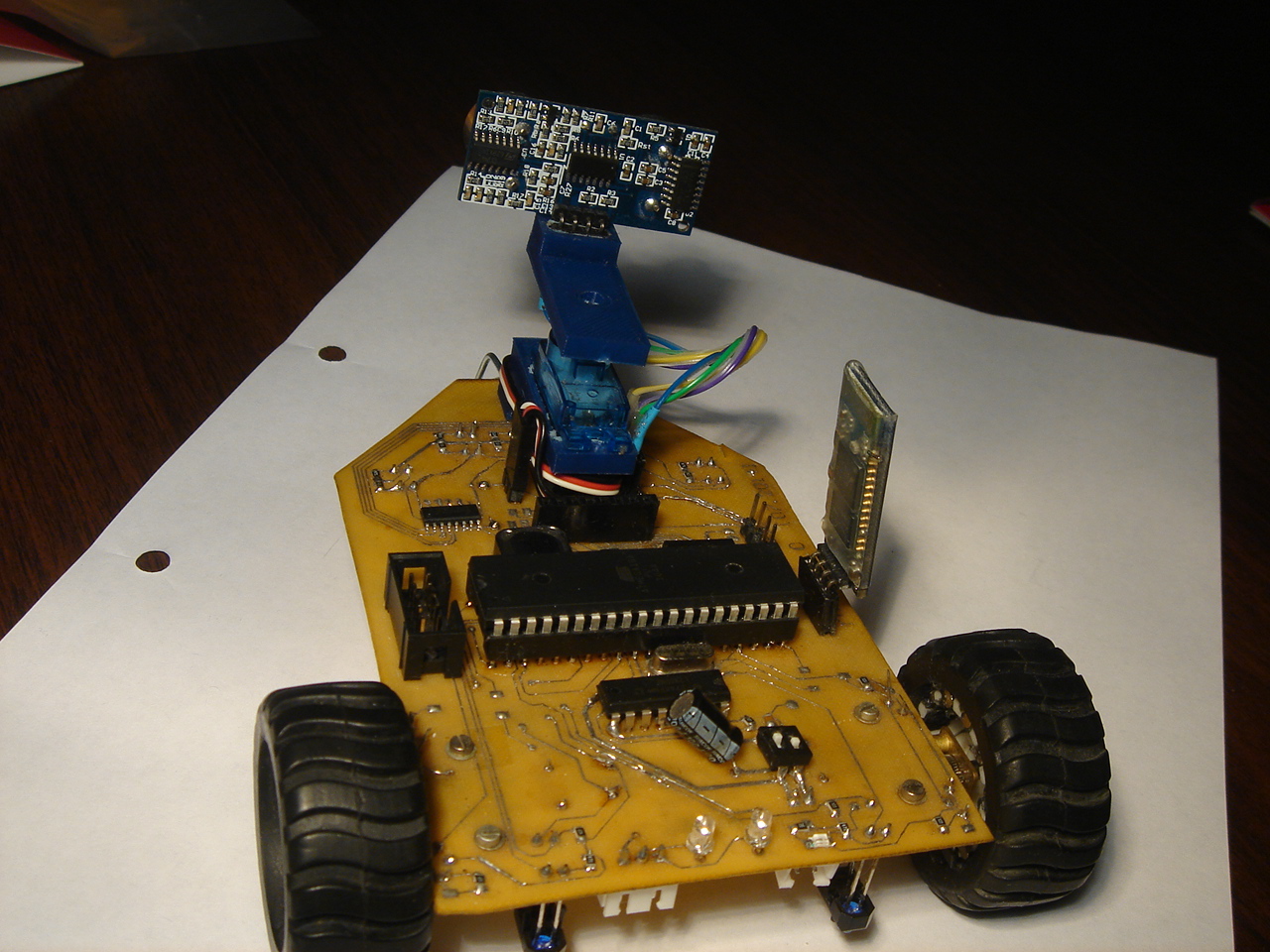
And yes, this is just a bead, a bead on a thick wire, and this is so far the only unsolved “problem” of the structure. In fact, I did not take up the decision on the question of the third wheel, because I caught fire with the wheels, the servo, etc.
Due to the use of 1mm PCB, the robot seems to be fluid, but since we have a small mass, this does not affect its strength and maneuverability.
Well, the first thing I wanted to ride on the line, so to speak the first experience with automated control.
I’ll say right away that I am not a programmer by profession and this is probably my weakest point in my hobby, so please do not criticize the code too much, in any case I am sure that I will need to rewrite the entire program in the future.
A test program was written that implemented the PD algorithm. It consisted of an ADC interrupt handler and the main data cycle itself.
How glad I was to see that the robot performs the function assigned to it, not so much as on steep videos with absolutely smooth and fast line-followers, but for me even this result was an achievement.
After that, I calmed down a bit with the programming part of the microcontroller itself and realized that in the future I would need to implement a robot control program from a PC and started studying Qt, and since I wrote the last program for PC only at the university (in Pascal), and that was something standard laboratory in computer science, my knowledge was in the region of zero.
The program was supposed to switch the operating modes of the robot (following the line, keyboard control, offline mode) and output (set) data from all sensors of interest (serves, line sensors, ultrasonic range finder, motors, encoders).
After a couple of weeks, the first version of the robot control panel was written. I liked working with the GUI in Qt - very convenient.

The program code will not be better inserted, so that they do not ban me for mocking C. In short, I’ll say that the program simply takes a data availability signal in QSerialPort and collects them according to labels and widgets, in response to a timer, if necessary, sends specifying data, such as the position of the servo and the speed of the motors. The green field in the program is in dreams - the future location map in front of the robot.
The program accepts all available data and temporarily acts as a debugger. He has not yet implemented control from the keyboard, and the autonomous mode is very raw and the robot is just seeing an obstacle, turns around at a given angle and tries to leave in a new direction. In general, as I said, the project as a whole is still damp in the program part.
In the future, I want to implement ambitious plans that stumble a little on the understanding that you need to redo both programs on the MK and PC completely, since I made a big mistake and started writing both programs like a bloated layer cake where one test module is adjacent to the other, and not as strict structured system. But the main thing is not to give up and create further until what you planned in your head is realized in the material world, because this is the meaning of a hobby.
P.S. In the future I will try to write one more part of the publication, so to speak as I progress in the program part.
In the second part of my publication, I will describe the process of creating and assembling my robot. Let's start with the manufacture of a printed circuit board and finish the video of the first steps (or, more correctly, scrolling the wheels) of our device. I will also pay attention to the first experience of PC programming in Qt, namely the creation of a control program and data exchange with the robot via Bluetooth.
If you want, you can familiarize yourself with the first publication and find out how it all began, but I’ll ask everyone else for a cat.
The last part ended with the fact that there was a ready layout of the printed circuit board in front of us, which means that it’s time to create and transfer our idea from the electronic version to the real tangible world, doesn’t that desire lie in the mind of every radio amateur, engineer, inventor ?! I only had 1mm textolite on my hands, so without thinking twice I began the process of transferring the track pattern to the board using standard LUT.
I apologize for the quality of the photos, but I have a cheap phone ...
')
The next step was etching! I tried a new method of etching with hydrogen peroxide and citric acid, which is certainly safe and very cheap, but it seemed to me too sensitive to the proportions of the components. After an hour of magical manipulation of the container with a solution, the process went with decent strength (it is worth saying that it was possible to change the board template and then everything would have worn out much faster).
80-90% of the tracks on the board turned out well, but because Most of the tracks were 0.2mm, mordants caught, which I removed with solder and thin conductors, thanks to them I made vias. In general, the whole process of soldering took 3 pm.
Motors had to be transferred to the bottom of the board, because I realized that I needed the maximum gap between the board and the surface on which I would need to drive, but still the robot turned out to be low-lying.
And since we remembered the motors, we also recall the idea with the encoder, since the magnets I ordered were literally half a millimeter in diameter less than the grooves in the wheel, they had to be fixed there somehow, but as we know everything ingenious is simple - I just took them and drove them there, filling the bay with a glue gun is not very aesthetic, but quickly and practically. The main thing is not to confuse the polarity, otherwise there will be shoals with accuracy, but it is already small - 12 magnets per wheel, i.e. 6 actuations per turn, and with a wheel diameter of 43mm, we get approximately 22mm of the distance traveled by the wheel in one operation.
On the board, in turn, with a small spacing in height, put the Hall sensors to understand which way we are going.
To attach the battery, serva and ultrasonic rangefinder were printed on a 3D printer, the simplest parts.
Battery holder
Servo holder.
UZ range finder holder.
A bit of fine-tuning of the parts with a file and everything fell into place, in the end, the robot turned out like this.
And yes, this is just a bead, a bead on a thick wire, and this is so far the only unsolved “problem” of the structure. In fact, I did not take up the decision on the question of the third wheel, because I caught fire with the wheels, the servo, etc.
Due to the use of 1mm PCB, the robot seems to be fluid, but since we have a small mass, this does not affect its strength and maneuverability.
Well, the first thing I wanted to ride on the line, so to speak the first experience with automated control.
I’ll say right away that I am not a programmer by profession and this is probably my weakest point in my hobby, so please do not criticize the code too much, in any case I am sure that I will need to rewrite the entire program in the future.
A test program was written that implemented the PD algorithm. It consisted of an ADC interrupt handler and the main data cycle itself.
Interrupt handler
#define FIRST_ADC_INPUT 2 #define LAST_ADC_INPUT 7 unsigned int real_adc[8]={0,0,0,0,0,0,0,0}; unsigned char sample_adc; volatile unsigned char adc_ready = 0; unsigned char leds[8]={0x21,0x41,0x61,0x63,0x23,0x43}; unsigned char adc_inputs[8]={0,1,2,4,6,7,3,5}; interrupt [ADC_INT] void adc_isr(void) //////////////ADC_INT { static unsigned char input_index=0; if (adc_ready == 0){ if (sample_adc == 0) { real_adc[input_index]=(signed int)(ADCW); if (input_index < LAST_ADC_INPUT-FIRST_ADC_INPUT){ input_index++; } else { input_index = 0; PORTB=leds[input_index]; sample_adc = 1; } ADMUX=(ADC_VREF_TYPE & 0xff)+adc_inputs[(FIRST_ADC_INPUT+input_index)]; ADCSRA|=0x40; } else { if (adc_ready==0) { if (ADCW > real_adc[input_index]){ real_adc[input_index]=(signed int)(ADCW); } else { real_adc[input_index]=(signed int)(real_adc[input_index]); } if (input_index < (LAST_ADC_INPUT-FIRST_ADC_INPUT)){ input_index++; PORTB=leds[input_index]; } else { input_index = 0; adc_ready = 1; PORTB&=~(1<<0); } ADMUX=(ADC_VREF_TYPE & 0xff)+adc_inputs[(FIRST_ADC_INPUT+input_index)]; } if (adc_ready == 0){ ADCSRA|=0x40; } } } } PID implementation
if (adc_ready == 1) { adc_l = (real_adc[1]+real_adc[2]); adc_r = (real_adc[3]+real_adc[4]); error = (adc_l-adc_r); delta_error = error - old_error; //sum_error += error; PID = Kp*error + Kd*delta_error + Ki*sum_error; old_error = error; if (PID > 0) { pwr_l += (signed int)PID ; pwr_r -= (signed int)PID ; } else { pwr_l += (signed int)PID ; pwr_r -= (signed int)PID ; } for(i=0; i < (LAST_ADC_INPUT-FIRST_ADC_INPUT)+1; i++){ real_adc[i]=0; } ADCSRA |= 0x40; adc_ready = 0; sample_adc = 0; } How glad I was to see that the robot performs the function assigned to it, not so much as on steep videos with absolutely smooth and fast line-followers, but for me even this result was an achievement.
After that, I calmed down a bit with the programming part of the microcontroller itself and realized that in the future I would need to implement a robot control program from a PC and started studying Qt, and since I wrote the last program for PC only at the university (in Pascal), and that was something standard laboratory in computer science, my knowledge was in the region of zero.
offtopic, about my grandiose plans to control the robot from a smartphone and how I gave up and scored on this idea
In general, I initially wanted to write a program for a mobile phone on Android, but did not want to learn Java, or rather did not want to leave C, and I have a friend who fumbled in Qt and he could ask a lot of things. At first, I myself tried to comprehend Zen of working with Qbluetooth and trying to dock with HC-05 with the help of my Chinese Jiayu g3, but every time I came across a problem that did not allow HC-05 to be friends. At first he sinned on Qbluetooth and said that he doesn’t perceive HC-05, but on the Internet he found information that people start data exchange through the bluetooth line of HC modules using QBluetooth or write their libraries, after complaining to a friend about their hard life, friend I wrote the program in one day and still managed to exchange data with the robot, but unfortunately through my tablet. As a result, having justified everything with the fact that my Chinese does not support rfcomm, I gave up and decided to write everything for a PC.
The program was supposed to switch the operating modes of the robot (following the line, keyboard control, offline mode) and output (set) data from all sensors of interest (serves, line sensors, ultrasonic range finder, motors, encoders).
After a couple of weeks, the first version of the robot control panel was written. I liked working with the GUI in Qt - very convenient.
The program code will not be better inserted, so that they do not ban me for mocking C. In short, I’ll say that the program simply takes a data availability signal in QSerialPort and collects them according to labels and widgets, in response to a timer, if necessary, sends specifying data, such as the position of the servo and the speed of the motors. The green field in the program is in dreams - the future location map in front of the robot.
The program accepts all available data and temporarily acts as a debugger. He has not yet implemented control from the keyboard, and the autonomous mode is very raw and the robot is just seeing an obstacle, turns around at a given angle and tries to leave in a new direction. In general, as I said, the project as a whole is still damp in the program part.
In the future, I want to implement ambitious plans that stumble a little on the understanding that you need to redo both programs on the MK and PC completely, since I made a big mistake and started writing both programs like a bloated layer cake where one test module is adjacent to the other, and not as strict structured system. But the main thing is not to give up and create further until what you planned in your head is realized in the material world, because this is the meaning of a hobby.
P.S. In the future I will try to write one more part of the publication, so to speak as I progress in the program part.
Source: https://habr.com/ru/post/256209/
All Articles