We are switching from STM32 to the Russian K1986BE92QI microcontroller. Practical application: Generate and reproduce sound. Part two: generate a sinusoidal signal. Mastering DMA
In the last article we managed to get the sound, but it was very expensive for us. First, we overclocked the controller to maximum speed. And secondly, apart from sound generation, the controller cannot do anything, since most of the CPU time is occupied by constantly updating the DAC value. Not good at it. Right now there is an urgent need to use DMA.
A week of hard work passed from the idea of using DMA to getting the first results. The first 3 days I tried to master it myself, but I could not get at least some result. Everything turned out only after the official forum gave me an example of DMA configuration for about the same task. After 4 days of his detailed study and detailed analysis of the documentation, a clear picture of the structure of the work of DMA appeared in my head.
Having opened the documentation I got into a stupor ... The main task at the initial stage of DMA mastering is to transfer some value to the DAC. And we will solve it. In DMA there are so-called "channels". They are a link between the receiver and the transmitter. In our case, between the memory and the periphery (DAC). What can be bundles - shown in the table.
As we see from the table - some channels are reserved for a certain periphery. There is no DAC in this periphery. The rest of the channels can be used for their intended purpose. The very first free channel is channel 8. We’ll be setting it up. But how? The documentation has a section Rules for data exchange .
Immediately find the registers to which these bits belong. But first you need to send a clocking signal to the DMA.
After submitting clocks, we need to enable DMA.
The next step is to enable the chnl_enable_set [C] bit. Here C denotes the channel number from zero.
After it is necessary to set to "0" chnl_req_mask_set [0] .
Everything would be fine, would write 0 and everything, but ...
Okay.
Here we need to install the unit on the channel we need.
Well, the last step for us should be writing a zero to the int_test_en bit [8] . But the existence of this bit is not written anywhere. So - skip it.
In addition, we assign our channel a high priority.
')
After turning on the channel, you need to decide on the mode of operation of the DMA.
As it turned out, in addition to registers, DMA also has settings structures. Honestly, for a very long time I delved into the principle of working with these structures. Earlier, at the time of STM32, I used a ready-made library, because the knowledge of the language was not enough to read the documentation. Now, albeit with some difficulty, but I can realize the whole principle of DMA work at a low level.
According to the documentation, the structure should be framed in this sequence.
I propose to begin by filling in the register setting cell.
We configured the channel configuration cell.
But the next step took me almost 4 days. The fact is that the address of each structure is strictly fixed and can only change with an offset of kilobytes.
Still a little explanation. The main thing is to have the necessary structure at the specified address. Data structures of the 7th channel or the 9th DMA do not care. They may not be. Technically, four 32-bit cells can be written to RAM at the indicated addresses and used. But there is a risk that the controller will change them during the execution of the program. Fill it in the program.
It remains only to specify the starting address of the array of structures in the DMA register -> CTRL_BASE_PTR .
As we remember, we set up DMA to stop after each transmission. Now, with the help of the system timer, we need to allow the transfer of the next data block to the DAC.
Next, in the interrupt of the system timer, we need to check whether the DMA passed everything. If so, you need to re-configure its structure. The fact is that after each transmission, DMA independently takes away from the number of transmissions by one. Therefore, after all transmissions - you need to restore the original value for the transmission of a sine wave again. After that, you need to allow the channel to work again (after the transfer, the channel becomes prohibited) and restart the transfer.
Although we managed to learn how to work with DMA, we still could not unload the processor. In the next article I will analyze the work of the timer and shift the work with DMA onto it, leaving the processor power for our needs.
Thank you very much I want to say to Yurock , who shared an example of a DMA configuration code under the DAC at the official official forum . Initially, I planned to write an article on the analysis of this example. For I understood with him about 3 days. It was too difficult for me. Using a timer and various structures.
Code example from the lesson.
DMA, or Direct Memory Access is a direct memory access technology, bypassing the central processor.- (c) from here .
A small digression.
A week of hard work passed from the idea of using DMA to getting the first results. The first 3 days I tried to master it myself, but I could not get at least some result. Everything turned out only after the official forum gave me an example of DMA configuration for about the same task. After 4 days of his detailed study and detailed analysis of the documentation, a clear picture of the structure of the work of DMA appeared in my head.
First impression.
The controller direct memory access MDR_DMA ............................................ ................................ 410
Having opened the documentation I got into a stupor ... The main task at the initial stage of DMA mastering is to transfer some value to the DAC. And we will solve it. In DMA there are so-called "channels". They are a link between the receiver and the transmitter. In our case, between the memory and the periphery (DAC). What can be bundles - shown in the table.
What can be bundles - shown in the table.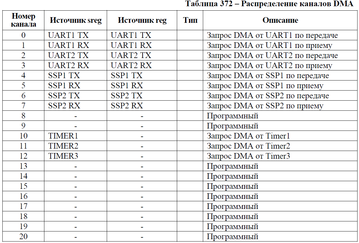

As we see from the table - some channels are reserved for a certain periphery. There is no DAC in this periphery. The rest of the channels can be used for their intended purpose. The very first free channel is channel 8. We’ll be setting it up. But how? The documentation has a section Rules for data exchange .
It contains the following.
Data exchange rules
The controller uses the data exchange rules listed below in Table 376, subject to the following conditions:
- the DMA channel is enabled, which is performed by setting the state of the logical unit of control bits chnl_enable_set [C] and master_enable;
- the request flags dma_req [C] and dma_sreq [C] are not masked, which is done by setting the control to the zero state of the control discharge chnl_req_mask_set [C];
- the controller is not in the test mode, which is done by setting the logic zero state of the control to int_test_en bit [C].
Immediately find the registers to which these bits belong. But first you need to send a clocking signal to the DMA.
We do this in the DMA setup function.
#define PCLK_EN_DMA (1<<5) // DMA. void DMA_Init_DAC (void) // DMA DAC. { RST_CLK->PER_CLOCK|=PCLK_EN_DMA; // DMA. } After submitting clocks, we need to enable DMA.
The DMA-> CFG register is responsible for this.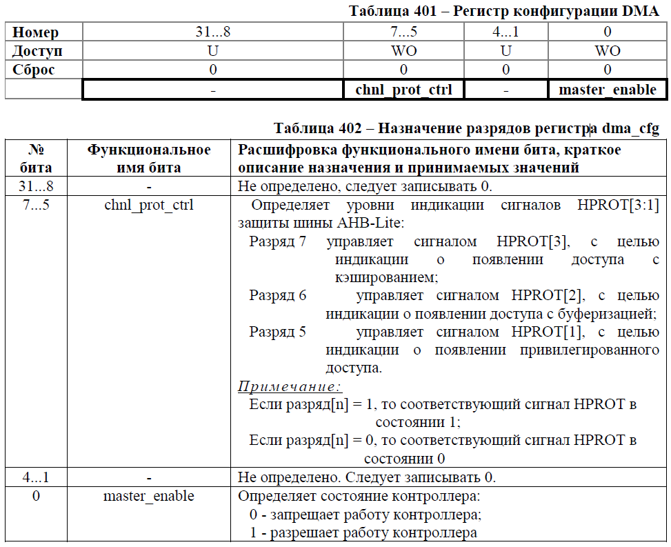
#define CFG_master_enable (1<<0) // . DMA->CFG = CFG_master_enable; // DMA. The next step is to enable the chnl_enable_set [C] bit. Here C denotes the channel number from zero.
It is in the register DMA-> CHNL_ENABLE_SET.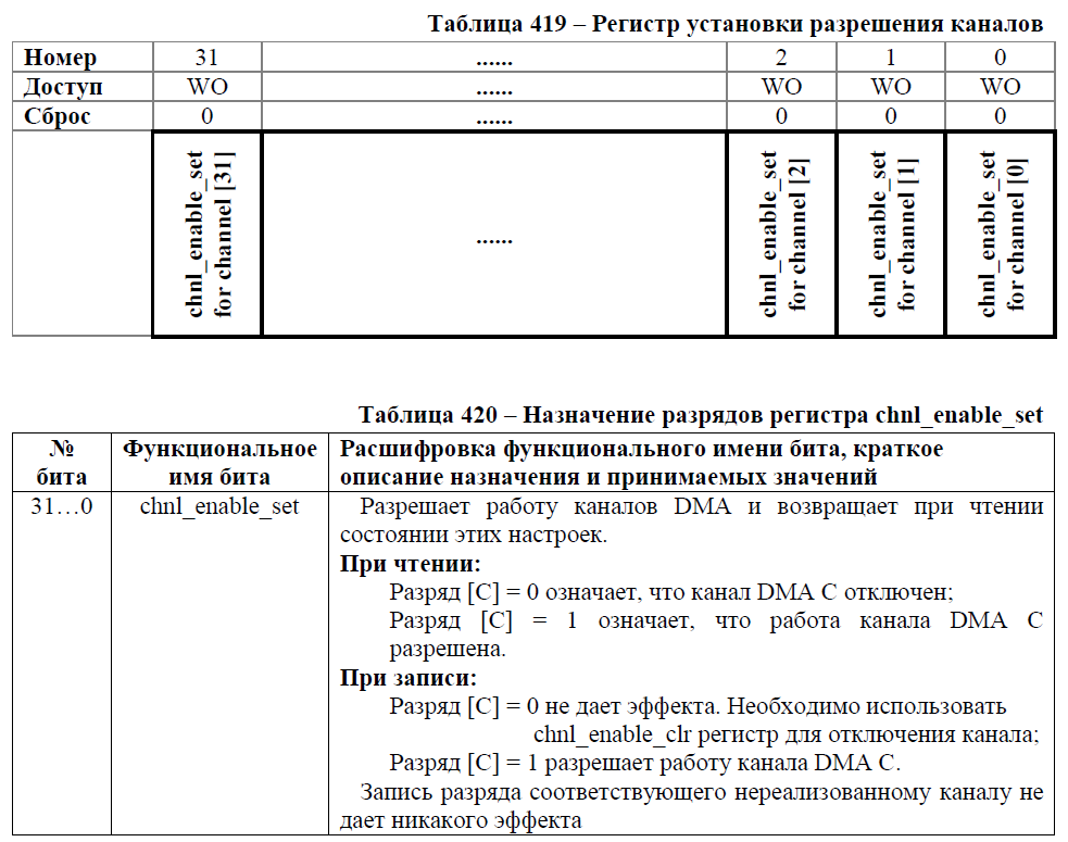
DMA->CHNL_ENABLE_SET = 1<<8; // DMA 8. After it is necessary to set to "0" chnl_req_mask_set [0] .
This bit is in the DMA-> CHNL_REQ_MASK_SET register.
Everything would be fine, would write 0 and everything, but ...
The discharge [C] = 0 has no effect. Nessesary to use
chnl_req_mask_clr register for permission
installation requests;
Okay.
We look the register DMA-> CHNL_REQ_MASK_CLR.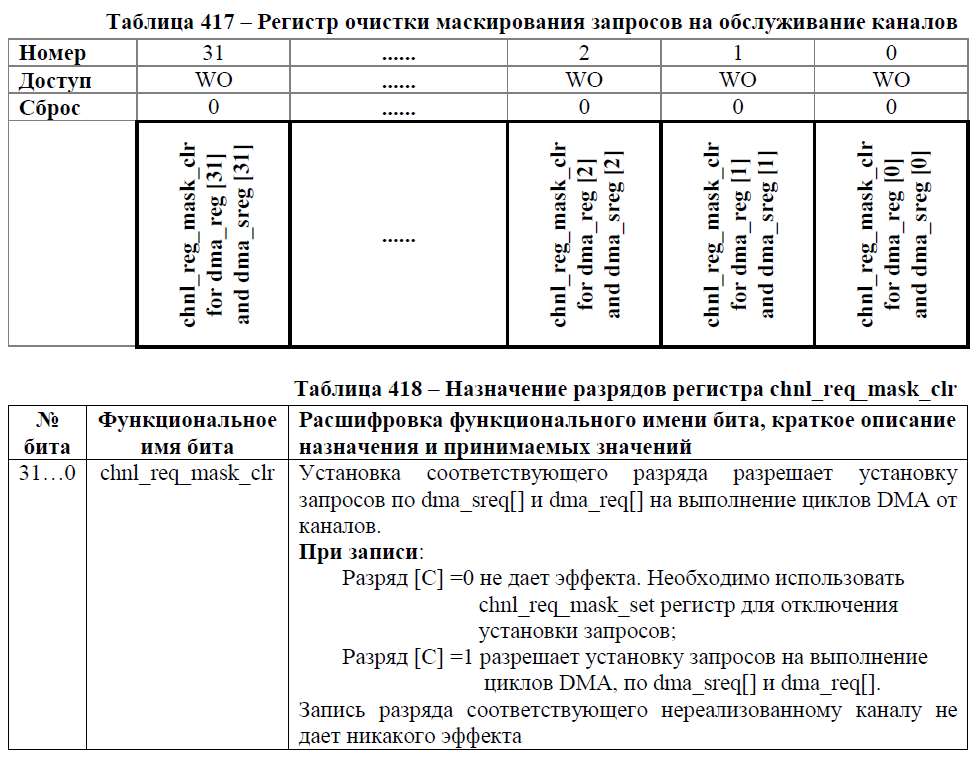
Here we need to install the unit on the channel we need.
DMA->CHNL_REQ_MASK_CLR = 1<<8; // DMA, dma_sreq[] dma_req[]. Well, the last step for us should be writing a zero to the int_test_en bit [8] . But the existence of this bit is not written anywhere. So - skip it.
In addition, we assign our channel a high priority.
For this there is a register DMA-> CHNL_PRIORITY_SET.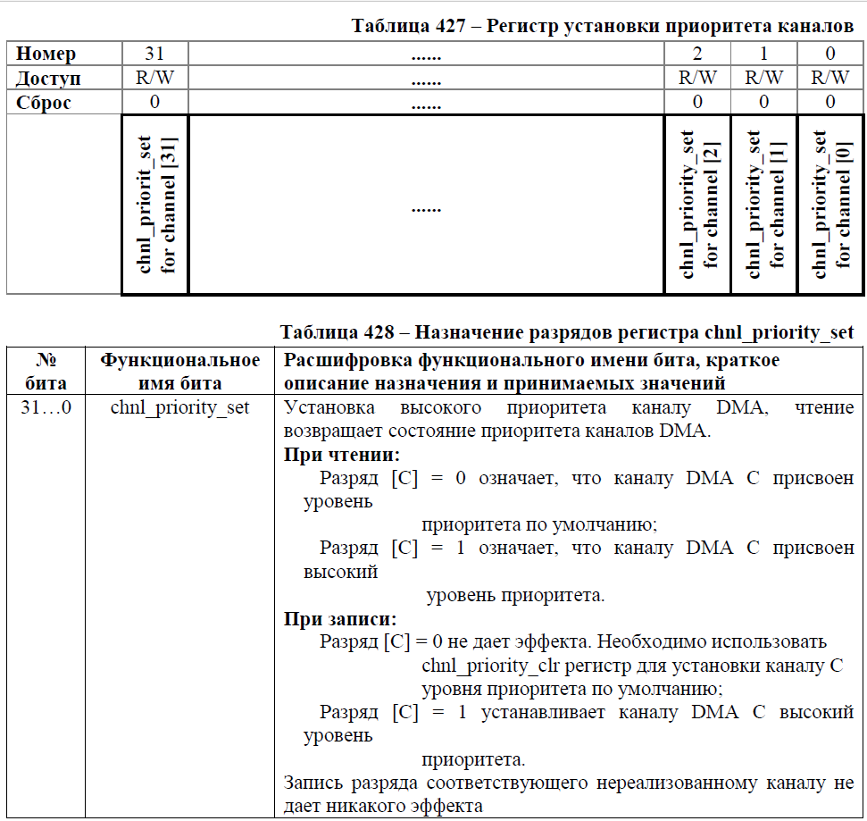

DMA->CHNL_PRIORITY_SET = 1<<8; // . ')
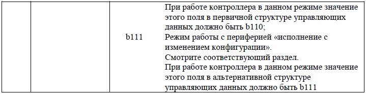
After turning on the channel, you need to decide on the mode of operation of the DMA.
There are 6 of them.
After analyzing everything, I decided that at the initial stage I would have enough of the “basic” mode.- not valid;
- the main;
- auto-request;
- "Ping pong";
- work with memory in the “execution with configuration change” mode;
- work with the periphery in the “execution with changing configuration” mode.
Here is a description of it.
We will deal with it in more detail when we fill in the structure of the DMA channel settings.Main
In this mode, the controller only works with the main or alternative channel control data. After the channel is enabled and the controller has received a request for processing, the DMA cycle is as follows:
1. The controller performs 2 ^ R transmissions. If the number of remaining gears is 0, the controller proceeds to step 3.
2. Arbitration:
- if the high-priority channel issues a processing request, the controller starts servicing this channel;
- if the peripheral unit or software issues a processing request (repeated processing request over the channel), then the controller proceeds to step 1.
3. The controller sets dma_done [C] to state 1 per clock cycle hclk. This tells the central processor to end the DMA cycle.
The structure of the DMA.
As it turned out, in addition to registers, DMA also has settings structures. Honestly, for a very long time I delved into the principle of working with these structures. Earlier, at the time of STM32, I used a ready-made library, because the knowledge of the language was not enough to read the documentation. Now, albeit with some difficulty, but I can realize the whole principle of DMA work at a low level.
For each channel of the channel should be set its own structure. It consists of four 32-bit cells.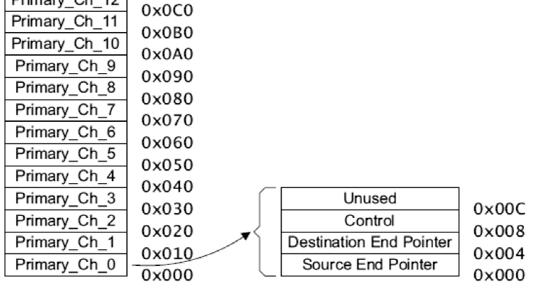

According to the documentation, the structure should be framed in this sequence.
- pointer to the end of the source data;
- pointer end data receiver;
- control bits;
- calculation of the address.
Filling the DMA channel structure
I propose to begin by filling in the register setting cell.
Select the offset address of the receiver (DAC).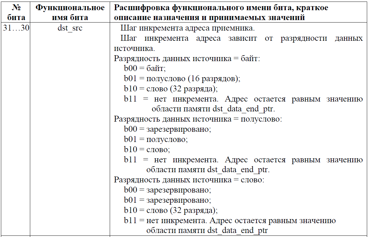 With us it does not change. The source and receiver have a half word length (16 bits). Our case:
 With us it does not change. The source and receiver have a half word length (16 bits). Our case:
Source data width = half word:
b11 = no increment. The address remains equal to the value of the dst_data_end_ptr memory area.
Select the dimension of the source and receiver data.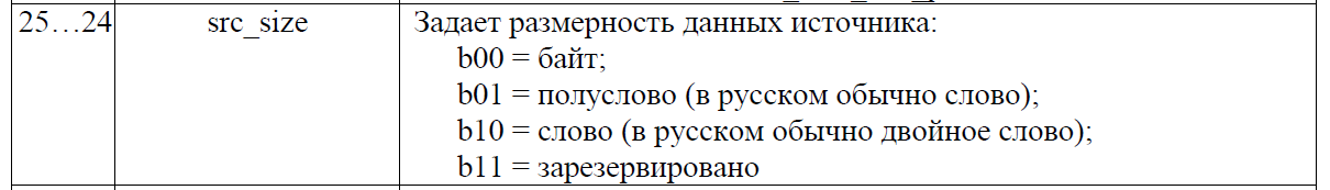 Here we choose the half-word. Since our array is uint16_t (16 bit).
  Here we choose the same half-word.
 Here we choose the half-word. Since our array is uint16_t (16 bit).
  Here we choose the same half-word.
We allow arbitration procedure.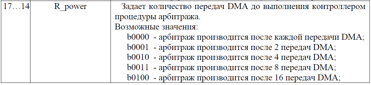
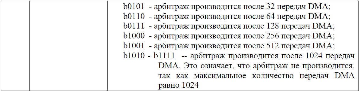
Here is the item for a long time kept me in ignorance. The fact is that DMA can not transfer the entire package at once, but in parts. For example, we have an array of 1024 elements. But we want to transmit 128 elements per second. To do this, we can set b0111 and after the transfer of 128 elements, the transfer will be interrupted before being restarted by the processor or peripherals. This will be useful when we associate a DMA with a timer. In our case, we leave zeros. As we need to transfer each element at a strictly specific moment. Simple transfer of the entire array does not suit us.


Here is the item for a long time kept me in ignorance. The fact is that DMA can not transfer the entire package at once, but in parts. For example, we have an array of 1024 elements. But we want to transmit 128 elements per second. To do this, we can set b0111 and after the transfer of 128 elements, the transfer will be interrupted before being restarted by the processor or peripherals. This will be useful when we associate a DMA with a timer. In our case, we leave zeros. As we need to transfer each element at a strictly specific moment. Simple transfer of the entire array does not suit us.
Set the length of the package.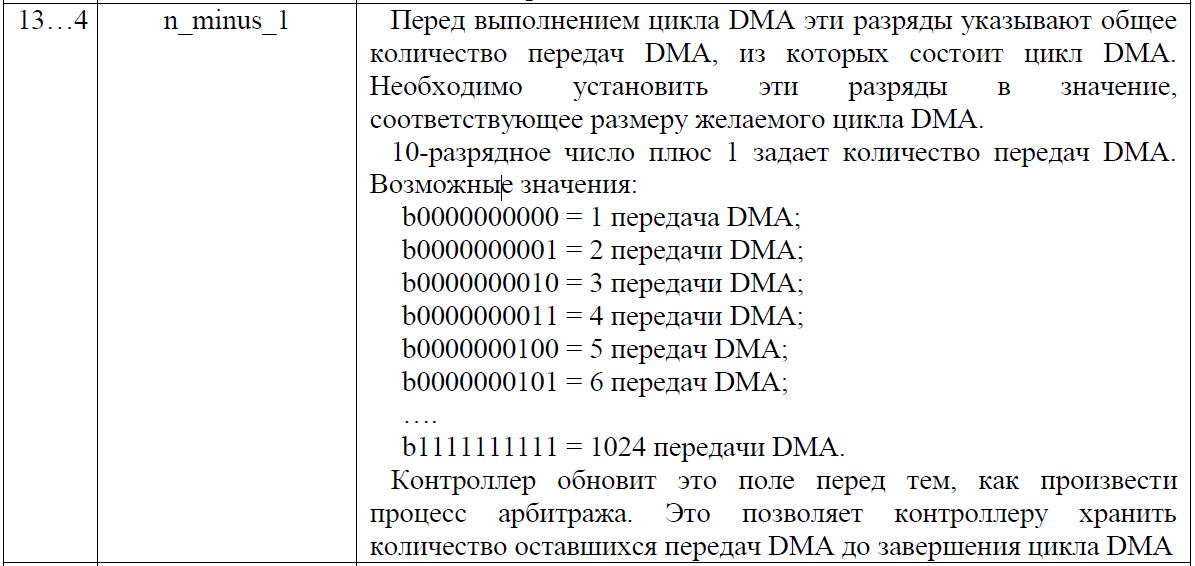
In the previous article, we passed an array of 100 elements in length. Therefore, here we will select 100-1 elements (Since 0 = one element).

In the previous article, we passed an array of 100 elements in length. Therefore, here we will select 100-1 elements (Since 0 = one element).
Unfortunately, I did not understand why this is necessary. Leave unchanged.
 We leave it unchanged so far.

 We leave it unchanged so far.
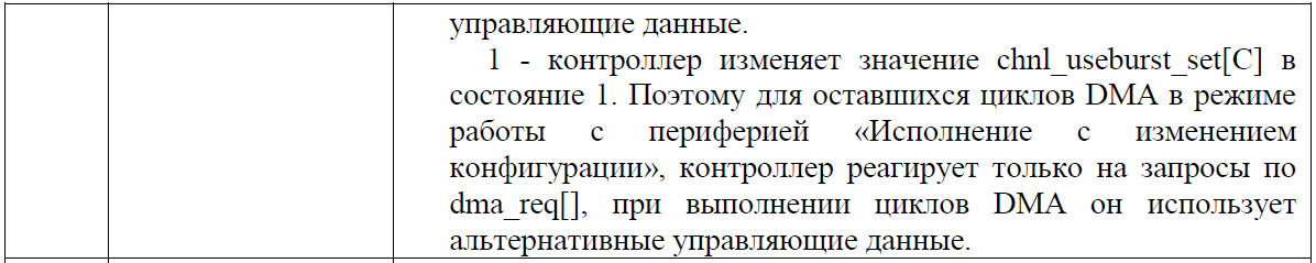
It remains only to select the mode.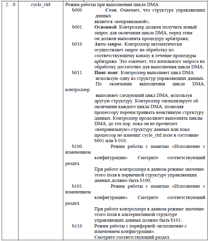
Select the "main" mode.


Select the "main" mode.
We configured the channel configuration cell.
We got the following.
// . #define dst_src (3<<30) // - 16 (). #define src_inc (1<<26) // 16 . #define src_size (1<<24) // 16 . #define dst_size (1<<28) // 16 . ( ). #define dst_prot_ctrl // (, , ) #define R_power (0<<14) // ( , ) . #define n_minus_1 (99<<4) //100 DMA. #define next_useburst (0<<3) // , ... #define cycle_ctrl (1<<0) // . // . #define ST_DMA_DAC_STRYKT dst_src|src_inc|src_size|dst_size|R_power|n_minus_1|next_useburst|cycle_ctrl Now we need to create an array of structures and write our settings there.
struct DAC_ST { uint32_t Destination_end_pointer; // . uint32_t Source_end_pointer; // uint32_t channel_cfg; // . uint32_t NULL; // . } But the next step took me almost 4 days. The fact is that the address of each structure is strictly fixed and can only change with an offset of kilobytes.
Take a look at the array of structures.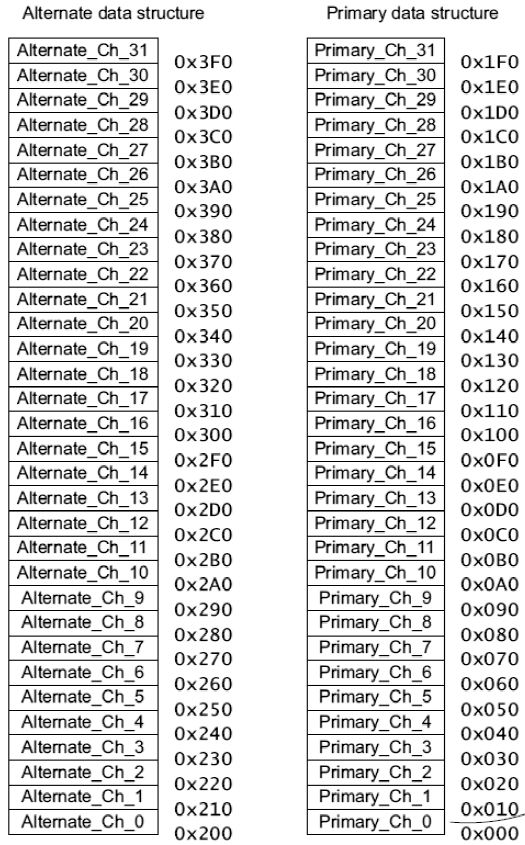
Each channel can have two structures. Primary and alternative. The alternative does not concern us yet (It is needed for other modes of operation). We are only interested in the primary (right column). In order for the controller to see our structure of the eighth channel configuration - it must be located at 0x20000080 or 0x20000280, or 0x20000480, etc. With this entry I wanted to show that the structure must be in RAM and must be aligned on the 1024 border bytes We describe this structure.
__align(1024) DAC_ST; struct DAC_ST DAC_ST_ADC[8] ; Still a little explanation. The main thing is to have the necessary structure at the specified address. Data structures of the 7th channel or the 9th DMA do not care. They may not be. Technically, four 32-bit cells can be written to RAM at the indicated addresses and used. But there is a risk that the controller will change them during the execution of the program. Fill it in the program.
DAC_ST_ADC[7].Destination_end_pointer = (uint32_t)C_4 + sizeof(C_4) - 1; // (C_4 - 100 ). DAC_ST_ADC[7].Source_end_pointer = (uint32_t)&(DAC->DAC2_DATA); // ( ) ( DAC) DAC_ST_ADC[7].channel_cfg = (uint32_t)(ST_DMA_DAC_STRYKT); // . DAC_ST_ADC[7].NULL = (uint32_t)0; // . It remains only to specify the starting address of the array of structures in the DMA register -> CTRL_BASE_PTR .
DMA -> CTRL_BASE_PTR = (uint32_t)&DAC_ST_ADC; The result of our setup has become.
#define CFG_master_enable (1<<0) // . #define PCLK_EN_DMA (1<<5) // DMA. // . #define dst_src (3<<30) // - 16 (). #define src_inc (1<<26) // 16 . #define src_size (1<<24) // 16 . #define dst_size (1<<28) // 16 . ( ). #define dst_prot_ctrl // (, , ) #define R_power (0<<14) // ( , ) . #define n_minus_1 (99<<4) //100 DMA. #define next_useburst (0<<3) // , ... #define cycle_ctrl (1<<0) // . // . #define ST_DMA_DAC_STRYKT dst_src|src_inc|src_size|dst_size|R_power|n_minus_1|next_useburst|cycle_ctrl struct DAC_ST { uint32_t Destination_end_pointer; // . uint32_t Source_end_pointer; // uint32_t channel_cfg; // . uint32_t NULL; // . } __align(1024) DAC_ST; struct DAC_ST DAC_ST_ADC[8] ; void DMA_and_DAC (void) { DAC_ST_ADC[7].Destination_end_pointer = (uint32_t)C_4 + sizeof(C_4) - 1; // (C_4 - 100 ). DAC_ST_ADC[7].Source_end_pointer = (uint32_t)&(DAC->DAC2_DATA); // ( ) ( DAC) DAC_ST_ADC[7].channel_cfg = (uint32_t)(ST_DMA_DAC_STRYKT); // . DAC_ST_ADC[7].NULL = (uint32_t)0; // . RST_CLK->PER_CLOCK|=PCLK_EN_DMA; // DMA. DMA->CTRL_BASE_PTR = (uint32_t)&DAC_ST_ADC; // . DMA->CFG = CFG_master_enable; // DMA. } We obtain a sinusoidal signal using DMA.
As we remember, we set up DMA to stop after each transmission. Now, with the help of the system timer, we need to allow the transfer of the next data block to the DAC.
Configure the timer.
void Init_SysTick (void) { SysTick->LOAD = 80000000/261.63/100-1; SysTick->CTRL |= CLKSOURCE|TCKINT|ENABLE; } Next, in the interrupt of the system timer, we need to check whether the DMA passed everything. If so, you need to re-configure its structure. The fact is that after each transmission, DMA independently takes away from the number of transmissions by one. Therefore, after all transmissions - you need to restore the original value for the transmission of a sine wave again. After that, you need to allow the channel to work again (after the transfer, the channel becomes prohibited) and restart the transfer.
volatile uint16_t Loop = 0; volatile uint32_t Delay_dec = 0; void SysTick_Handler (void) { if ((DAC_ST_ADC[7].channel_cfg & (0x3FF<<4)) == 0) { DAC_ST_ADC[7].channel_cfg = (uint32_t)(ST_DMA_DAC_STRYKT); } // DMA. DMA->CHNL_ENABLE_SET = 1<<8; // DMA 8. DMA->CHNL_SW_REQUEST = 1<<8; // . } Instead of a conclusion.
Although we managed to learn how to work with DMA, we still could not unload the processor. In the next article I will analyze the work of the timer and shift the work with DMA onto it, leaving the processor power for our needs.
Thank you very much I want to say to Yurock , who shared an example of a DMA configuration code under the DAC at the official official forum . Initially, I planned to write an article on the analysis of this example. For I understood with him about 3 days. It was too difficult for me. Using a timer and various structures.
Code example from the lesson.
List of previous articles.
1. We turn from STM32F103 to K1986BE92QI. Or the first acquaintance with the Russian microcontroller.
2. We are switching from STM32 to the Russian K1986BE92QI microcontroller. Setup project in keil and flashing LED.
3. We are switching from STM32 to the Russian K1986BE92QI microcontroller. System Timer (SysTick).
4. We are switching from STM32 to the Russian K1986BE92QI microcontroller. Setting the clock frequency.
5. We are switching from STM32 to the Russian K1986BE92QI microcontroller. Practical application: Generate and reproduce sound. Part one: we generate a square and sinusoidal signal. Mastering the DAC (DAC).
Source: https://habr.com/ru/post/256091/
All Articles