New life shooting gallery
Hello. I had a chance to realize an interesting project with the use of microcontrollers, namely, to revive the lifting mechanisms of targets for a shooting gallery, so I decided to share the result of my creation.
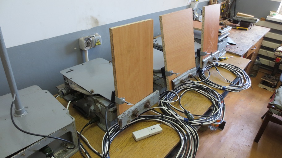
Not every day there are such projects. The bottom line is this. There are four lifting mechanisms for rifle targets, and depending on the rifle exercise, the operator must control the lifting of each target from a distance. After the target is set to the ready mode by the operator, the shooter can fire shots. The lifting mechanism is equipped with a shock sensor with which the impact is recorded. As soon as the sensor detects a hit, it accordingly lowers the affected target. There is no particular difficulty in the implementation of this task. But!..
As it happens in most cases, there was no documentation on these mechanisms. The lifting mechanisms themselves were disassembled, there was also no multicore screened cable to the operator.
Considering that targets can be set at a distance of up to three hundred meters, the purchase of a multicore shielded cable of such length bites at a very high price. Assessing the deplorable situation, they began to look for a way out of it.
')
After talking with the customer, they came to the following. To control the targets without using any wires going to the operator, it was decided to implement remote radio control of the lifting targets.
I wanted to make the remote control myself using a radio module, or buy an inexpensive ready-made radio extension suitable for our tasks. But the radio receiver, without consulting, the customer purchased himself.

This remote control allows you to remotely control the line of sight at a distance of up to 3,000 meters. And this is at a power of 10 milliwatts of the transmitter, at a frequency of 315 MHz. I did not find the data on the sensitivity of the receiver itself, and there was no desire and need to measure. As expected, when testing this device on line of sight, confident work amounted to 150 meters. But you need 300! After conjuring a little with this device and changing the antenna design (using the X1-50 characterizer, I coordinated and tuned the antenna) to a quarter-wave dipole, I was able to significantly increase the range of the radio module. Therefore, this remote control and left.
After the radio control met the requirements, the customer wanted to equip each target with this remote control in order to be able to independently control each target. A discussion began on whether to use four consoles at all. On the one hand, the independent management of each target gave a number of advantages, but the purchase of four consoles is an additional waste of money, besides, they are inconvenient to use. Having discussed which shooting exercises will be used, and there are only three of them, as it turned out, they came to the conclusion that the console needs one - to start the exercise or to cancel. All other operations were assigned to the microcontroller.
Shooting exercises:
The first exercise:
Three targets simultaneously rise with a time interval of 10 seconds. The shooter in the allotted time should hit the target. With the defeat of the shooter, the target is lowered, upon completion of the allotted time, the remaining unaffected targets are also lowered. The exercise is over.
The second exercise:
Three targets simultaneously rise with an unlimited time interval (until you press to cancel the exercise). As soon as all three targets hit, the fourth target rises and is held until it hits.
Third exercise:
This shooting exercise is the most active in terms of writing a program for a microcontroller. In the shooting exercise involved three targets. The exercise is considered complete when three targets have worked, and it is not necessary for all targets to participate, one target can work three times. This target will rise three times in a row with a time interval of 6 seconds, and the remaining two will not participate at all. Or, two targets can simultaneously rise with a time interval of 6 seconds, then descend. Then one of the three targets can rise, provided that it is not hit by the shooter, etc. The target does not rise only when it is hit by the shooter. In general, the targets should act chaotically with each new start of this exercise, and if possible not be repeated in a row. There are still many different conditions, I will not describe the whole process, for this I made a video where you can watch both the constructive aspects and the operation of the lifting mechanisms in action. I will say one thing that I had to tinker with writing a program for the microcontroller.
Given that the units are dismantled, we decided to assemble the control of the lifting mechanisms on the microcontrollers. One unit served as a presenter, and communicated with other USART units, controlling the operation of each lifting mechanism. The rest of the lifting mechanisms were driven, and connected to the master via a shielded cable.
There was no need for a special data transfer rate, so I chose a standard data transfer rate of 9,600 bps. Also on the master unit with the help of a toggle switch, a selection of shooting exercises was carried out.

The problem arose with the control of the collector engine with sequential excitation. Structurally, the lifting mechanism is made so that the target must be stopped at a certain moment, not earlier and not later. Otherwise, the target under its own weight could lean in front and back, and this is no longer good. Just disconnecting the collector engine was not enough. Due to the inertia of the gearbox continued movement. For this reason, implemented dynamic braking of the collector engine. Stopping the engine was carried out hard and instantly.
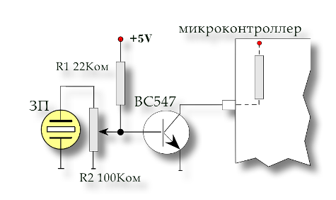
Due to the lack of shock sensors for targets, the question arose about their manufacture. For manufacturing the shock sensor, a piezo sensor was used. The sensor connected to the microcontroller, according to the diagram, showed itself quite well. By adjusting the variable resistor, you can adjust the sensitivity of the sensor to shocks.
The next step in building a shock sensor was the question of how to attach them to targets, because the targets on the lifting mechanisms will be replaced. Hence, the shock sensor should be easily removed from the target, respectively, and installed on it. The fastener was manufactured according to the clamping principle, and the sensor was fixed to the lower part of the target. Given that the lifting mechanism will be below ground level, the sensor will not suffer from a bullet hit.

More clearly the constructive aspects of the device, as well as the work itself, I demonstrate in this video:
Source: https://habr.com/ru/post/256009/
All Articles