We do the IR remote control for the camera

Sometime recently, I needed to remotely control the SLR shutter. The wired version was discarded, uncomfortable. Searching for shopping, found the ML-L3 remote. But I did not want to give him a thousand rubles, especially since the function performed at first glance is elementary. I decided to do it myself. And then, by the way, the weekend arrived, and the work began to boil ...
Theory or how it works
At first there was hope that you can find all the codes and a description of how the IR remote control works on the network. But in the end, managed to find only a description of the sequence that needs to be generated to trigger the shutter. Here is a drawing of such a parcel for Nikon cameras:
')
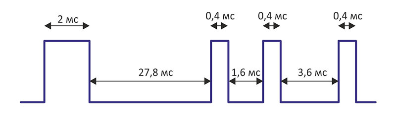
As you can see, nothing complicated. The fill rate is 38.4 kHz.
For Canon cameras, the sequence is even simpler:
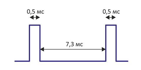
They have a frequency of filling - 33 kHz.
Circuit, PCB and Parts
I wanted to not only repeat the console, but also provide it with additional functionality. As a result, I decided to add a timer for shooting Timelapse video and the ability to control Nikon and Canon cameras. Based on the spare parts in stock, the following scheme was created:
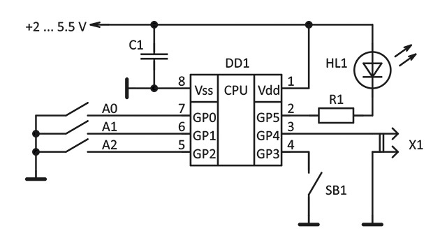
DD1 - PIC12F629
HL1 - ARL2-5013IRAB-940NM
R1 - 150 Ohm
SB1 - Clock button FSM4JH
A0 - DIP Switch DS1040-03RN
C1 - Tantalum Capacitor, 47 μF x 10 V, Type B
+ Battery compartment BH-624 (1xAAA)
The total cost of all the details is 240 rubles (at prices for April 2015, not in the cheapest store in the city).

The selected microcontroller has high power I / O ports, which allows switching an infrared LED without an additional key. Button SB1 generates the selected sequence. There is no power switch; the microcontroller is constantly in sleep mode and consumes 70 nanoamperes, “waking up” only for the time of signal generation. Jumper X1 switches camera type: installed - Canon, unchecked - Nikon. Switches A0 ... A2 set the period of the timer for shooting Timelapse video:
| A2 | A1 | A0 | Period |
|---|---|---|---|
| 0 | 0 | 0 | not |
| 0 | 0 | one | 2 seconds |
| 0 | one | 0 | 4 seconds |
| 0 | one | one | 8 seconds |
| one | 0 | 0 | 15 seconds |
| one | 0 | one | 30 seconds |
| one | one | 0 | 1 minute |
| one | one | one | 2 minutes |
The designed circuit board, as well as the circuit, is very simple:

Manufactured PCB standard LUT method and assembled:

Microcontroller source code
errorlevel 0, -207, -205, -302, -203
#include <P12F629.INC>
__CONFIG _CPD_OFF & _CP_OFF & _BODEN_OFF & _MCLRE_ON & _PWRTE_ON & _WDT_OFF & _INTRC_OSC_NOCLKOUT
LED equ 5; IR LED
CFG equ 4; Nikon (1) / Canon (0)
; ================================================ ==============================
; Variables
; ================================================ ==============================
CBLOCK 0x020
DEL
DEL_MS
IMP
COUNT
ENDC
; ================================================ ==============================
; Reset
; ================================================ ==============================
ORG 0
GOTO START
; ================================================ ==============================
; Interruptions
; ================================================ ==============================
ORG 4
RETFIE
; ================================================ ==============================
; Subprograms
; ================================================ ==============================
; The delay routine (in microseconds, 770 μs max)
; (Before calling, put the delay value in W)
DEL_MK MOVWF DEL
M1 DECFSZ DEL, F
GOTO M1
RETLW 0
; The delay routine (in milliseconds, 256 ms max)
; (Before calling, put the delay value in W)
DEL_M MOVWF DEL_MS
MOVLW 0xA5
M2 CALL DEL_MK
CALL DEL_MK
DECFSZ DEL_MS, F
GOTO M2
RETLW 0
; Nikon pulse output routine (38.4 kHz padding)
; (Before calling, put the pulse duration in W)
NIK MOVWF IMP
M3 BCF GPIO, LED
MOVLW 0x02
CALL DEL_MK
NOP
BSF GPIO, LED
MOVLW 0x01
CALL DEL_MK
NOP
DECFSZ IMP, F
GOTO M3
RETLW 0
; Signal output routine for Nikon
NIKON MOVLW 0x4D
CALL NIK; pulse 2 ms
MOVLW 0x12
CALL DEL_M; pause 27.8 ms
MOVLW 0x47
CALL DEL_MK
MOVLW 0x0F
CALL NIK; pulse 0.4 ms
MOVLW 0x01
CALL DEL_M; 1.6 ms pause
MOVLW 0x69
CALL DEL_MK
MOVLW 0x0F
CALL NIK; pulse 0.4 ms
MOVLW 0x02
CALL DEL_M; 3.6 ms pause
MOVLW 0xFF
CALL DEL_MK
MOVLW 0x0F
CALL NIK; pulse 0.4 ms
RETLW 0
; Canon pulse subroutine (33 kHz padding)
; (Before calling, put the pulse duration in W)
CAN MOVWF IMP
M4 BCF GPIO, LED
MOVLW 0x02
CALL DEL_MK
NOP
NOP
NOP
BSF GPIO, LED
MOVLW 0x01
CALL DEL_MK
NOP
NOP
NOP
DECFSZ IMP, F
GOTO M3
RETLW 0
; Canon signal output routine
CANON MOVLW 0x13
CALL CAN; pulse 0.5 ms
MOVLW 0x05
CALL DEL_M; 7.3 ms pause
MOVLW 0x13
CALL CAN; pulse 0.5 ms
RETLW 0
; Delay subroutine for 1 second 0xA1
DEL_1S MOVLW 0xFF
CALL DEL_M
MOVLW 0xFF
CALL DEL_M
MOVLW 0x88
CALL DEL_M
RETLW 0
; ================================================ ==============================
; Main program
; ================================================ ==============================
START BCF STATUS, RP0; Bank 0 selected
MOVLW B'00000000 '
MOVWF INTCON
MOVLW B'00000111 '
MOVWF CMCON; Turning off the built-in comparators
BSF STATUS, RP0; Bank 1 selected
MOVLW B'00000111 '
MOVWF OPTION_REG
CALL 3FFh; Download generator calibration constant
MOVWF OSCCAL
MOVLW B'00011111 '; Ports (direction)
MOVWF TRISIO
MOVLW B'00010111 '; Pull-up resistors
MOVWF WPU
BCF STATUS, RP0; Bank 0 selected
MOVLW B'00100000 '; Ports
MOVWF GPIO
; --------------------------
MOVLW 0x12
CALL DEL_M
LP1 BTFSS GPIO, CFG
CALL CANON
BTFSS GPIO, CFG
GOTO LP2
CALL NIKON
LP2 MOVF GPIO, W; Count jumpers
ANDLW B'00000111 '
ADDLW B'11111000 '
MOVWF COUNT
COMF COUNT, F
BTFSC STATUS, Z; Shutdown if not
SLEEP
MOVF COUNT, W
XORLW 0x01; 1 timing enabled
BTFSC STATUS, Z
GOTO SET2
MOVF COUNT, W
XORLW 0x02; 2 timing enabled
BTFSC STATUS, Z
GOTO SET4
MOVF COUNT, W
XORLW 0x03; 3 timing enabled
BTFSC STATUS, Z
GOTO SET8
MOVF COUNT, W
XORLW 0x04; 4 timing enabled
BTFSC STATUS, Z
GOTO SET15
MOVF COUNT, W
XORLW 0x05; 5 timing enabled
BTFSC STATUS, Z
GOTO SET30
MOVF COUNT, W
XORLW 0x06; 6 timing enabled
BTFSC STATUS, Z
GOTO SET1M
GOTO SET2M; 7 timing enabled
SET2 MOVLW 0x02
GOTO TIME
SET4 MOVLW 0x04
GOTO TIME
SET8 MOVLW 0x08
GOTO TIME
SET15 MOVLW 0x0F
GOTO TIME
SET30 MOVLW 0x1E
GOTO TIME
SET1M MOVLW 0x3C
GOTO TIME
SET2M MOVLW 0x78
GOTO TIME
TIME MOVWF COUNT
LP3 CALL DEL_1S
DECFSZ COUNT, F
GOTO LP3
GOTO LP1
END
Hull design
Modern 3D printing technologies have solved the long-standing problem of home-made products - replaced by clumsy and impartial cases came quality-looking design, not inferior to industrial designs.
The body of this console is designed in SolidWorks, with the calculation of the subsequent printing on a 3D printer. It is made in the best traditions of Chinese design - not a single screw, all snap.
The resulting dimensions are largely due to the choice of power source. After brief deliberation, it was decided not to use the lithium cell, which is traditional in such cases. For the Timelapse mode with the constant generation of the parcel is able to discharge a weak element rather quickly. Therefore, 2 AAA batteries are used.

Printed on 3D printer case:

Schema, PCB, source code and files for printing the case can be downloaded from here .
Assembly
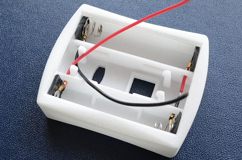
Before assembly, you must carefully cut the flat parts with contacts with a knife from the battery holders:
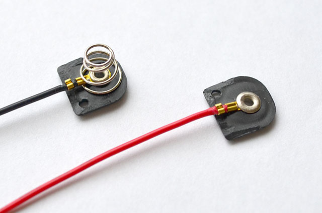
The resulting contacts should be glued to the body, observing the polarity:
Then put the button and insert the board all the way, making sure that it snaps into place. It remains to solder the wires from the batteries to the board and the device is ready:
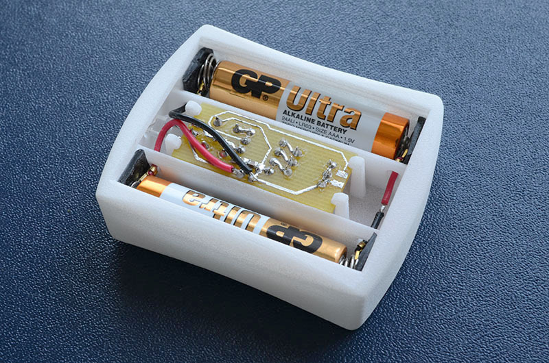
Here is the assembled IR remote control:

Camera setting
Before using the remote control, you need to perform a simple setup of the camera to control it through the IR remote control. It is different for each model. I’m giving an algorithm for my Nikon D7000: 1) turn the left ring to the remote icon, as in the photo on the left 2) set the required response in the “Remote Control Mode” menu.

Source: https://habr.com/ru/post/255667/
All Articles