Levitron on Arduino
Good evening! In this publication I will talk about my little homemade product, which I had planned for a long time.
Some time ago I read an article about interesting devices - Levitrons , which are both purely mechanical and electronically controlled.
Naturally, I wanted to collect such a toy for myself, but, searching on the Internet, to my surprise I found (at least at that time) that most of the circuits were exclusively analog. Since I understand little in analog technology, I decided to “reinvent” Levitron again. For experiments, the Arduino Uno was at hand. He ordered a linear Hall sensor in China (what is the Hall effect ), namely the UGN3503UA, collected a number of old transformers for winding test coils and began experiments.
')
That's what came out of it:
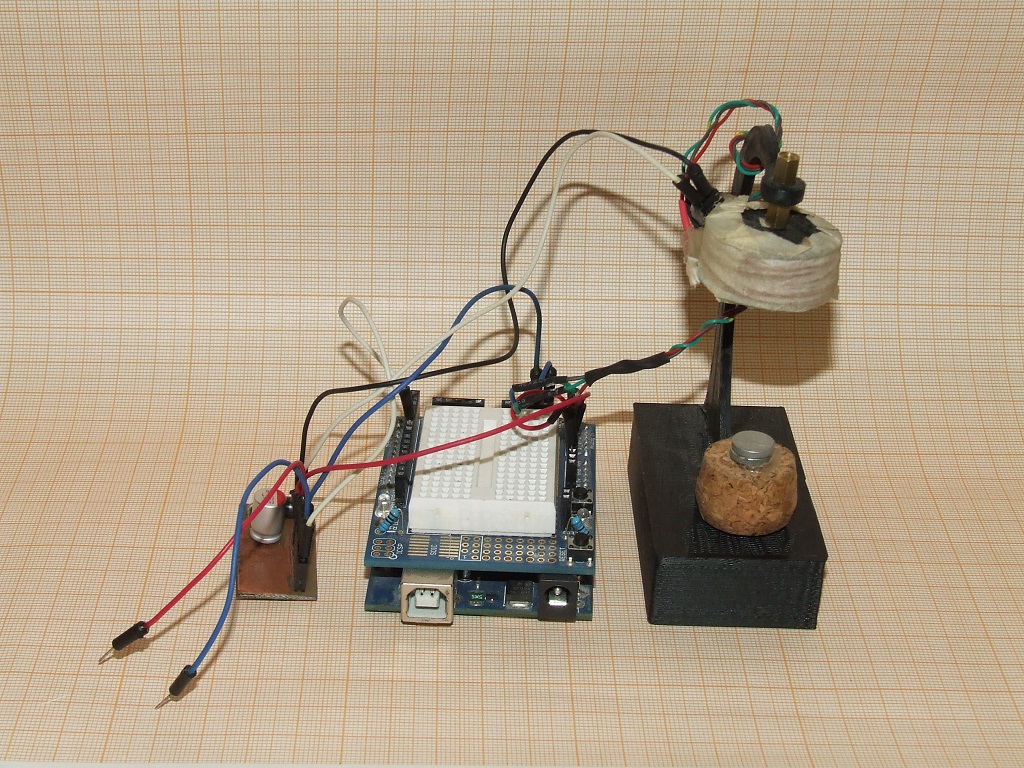
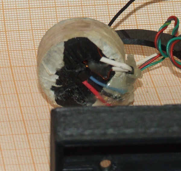
How it works. At the bottom of the coil in the center there is a Hall sensor, measuring the distance to the neodymium magnet, which is glued to the “levitating” traffic jam. The sensor has three outputs - 5V power and analog output, which is connected to the Arduino ADC.
The control solenoid circuit is assembled on a field-effect transistor.
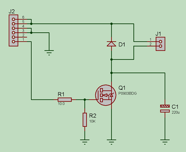

The solenoid is connected to the J1 pins, pin 1 of the J2 connector to the Arduino PWM. Connecting a Hall sensor to the input of the ADC is not on the diagram, but there should be no difficulties here.
I can’t say the number of turns of the coil, as I made 3 or 4 coils during the experiments, shook it according to the principle “how many wires are left on the transformer”. The remaining parameters: coil resistance of about 12 ohms, diameter 30 mm, height 10 mm, wire thickness 0.3 mm, coil without a core.
The firmware in the first version was extremely simple; when the value leaves the permissible range, the circuit either turns off or turns on at full capacity; in the video above, the device just works according to this algorithm. In the next firmware version, the MC tries to smoothly adjust the voltage on the solenoid, as a result of which the tendency to oscillations in the system has decreased.
The circuit is powered by 12V, the sensor is powered by the built-in Arduino stabilizer. Consumption in maximum mode is about one amp, in hover mode 0.3-0.4 A.
The device has worked, but for more than one minute it is dangerous to work, the transistor is very hot, the coil is also heated, until the glue melts (everything is assembled on hot melt).
I plan to further remake the solenoid and transfer the circuit to power from 5 volts, put a more powerful transistor with a radiator. Well, replace the Arduino with ATiny. It does not hurt to also put a large-capacity capacitor on the input circuits, or even a battery of capacitors to protect the power supply (the first power supply is 1.5A, it burns down after 10 seconds of operation from load jumps).
On this, perhaps, finish, thank you for your attention.
Some time ago I read an article about interesting devices - Levitrons , which are both purely mechanical and electronically controlled.
Naturally, I wanted to collect such a toy for myself, but, searching on the Internet, to my surprise I found (at least at that time) that most of the circuits were exclusively analog. Since I understand little in analog technology, I decided to “reinvent” Levitron again. For experiments, the Arduino Uno was at hand. He ordered a linear Hall sensor in China (what is the Hall effect ), namely the UGN3503UA, collected a number of old transformers for winding test coils and began experiments.
')
That's what came out of it:
How it works. At the bottom of the coil in the center there is a Hall sensor, measuring the distance to the neodymium magnet, which is glued to the “levitating” traffic jam. The sensor has three outputs - 5V power and analog output, which is connected to the Arduino ADC.
The control solenoid circuit is assembled on a field-effect transistor.
The solenoid is connected to the J1 pins, pin 1 of the J2 connector to the Arduino PWM. Connecting a Hall sensor to the input of the ADC is not on the diagram, but there should be no difficulties here.
I can’t say the number of turns of the coil, as I made 3 or 4 coils during the experiments, shook it according to the principle “how many wires are left on the transformer”. The remaining parameters: coil resistance of about 12 ohms, diameter 30 mm, height 10 mm, wire thickness 0.3 mm, coil without a core.
The firmware in the first version was extremely simple; when the value leaves the permissible range, the circuit either turns off or turns on at full capacity; in the video above, the device just works according to this algorithm. In the next firmware version, the MC tries to smoothly adjust the voltage on the solenoid, as a result of which the tendency to oscillations in the system has decreased.
Firmware
#define sensorPin A0 #define pwmPin 6 int sensorValue = 0; int levitPoint = 370; int deltaLevit = 5; int maxL, minL; byte induction = 128; void setup() { pinMode(pwmPin, OUTPUT); maxL = levitPoint - deltaLevit; minL = levitPoint + deltaLevit; } int sensorRead(int sensorPin) { int s = 0; for(byte i =0; i < 5; i++) {s += analogRead(sensorPin);} return s/5; } void loop() { sensorValue = sensorRead(sensorPin); if (sensorValue < 490) { if (sensorValue < maxL) induction = 0; if (sensorValue > minL) induction = 250; if (sensorValue >= maxL and sensorValue <= minL) induction = ((sensorValue - maxL)*25); } else induction = 0; analogWrite(pwmPin, induction); } The circuit is powered by 12V, the sensor is powered by the built-in Arduino stabilizer. Consumption in maximum mode is about one amp, in hover mode 0.3-0.4 A.
The device has worked, but for more than one minute it is dangerous to work, the transistor is very hot, the coil is also heated, until the glue melts (everything is assembled on hot melt).
I plan to further remake the solenoid and transfer the circuit to power from 5 volts, put a more powerful transistor with a radiator. Well, replace the Arduino with ATiny. It does not hurt to also put a large-capacity capacitor on the input circuits, or even a battery of capacitors to protect the power supply (the first power supply is 1.5A, it burns down after 10 seconds of operation from load jumps).
On this, perhaps, finish, thank you for your attention.
Source: https://habr.com/ru/post/255647/
All Articles