We are switching from STM32 to the Russian K1986BE92QI microcontroller. Clock Setting
Understanding the clocking system
In the last article, we learned how to create stable delays using a simple SysTick timer, and also a little plunged into the interrupt operation mechanism. Then we took as a postulate that by clocking the timer from the source of the HCLK - we get 8 MHz. Now it's time to figure out where these numbers come from.
After opening the documentation and making the transition to the “Clock Signals MDR_RST_CLK” we can see such a table.
Built-in RC HSI Generator
The HSI generator generates a clock frequency of 8 MHz. The generator automatically starts when the power of the UCC.
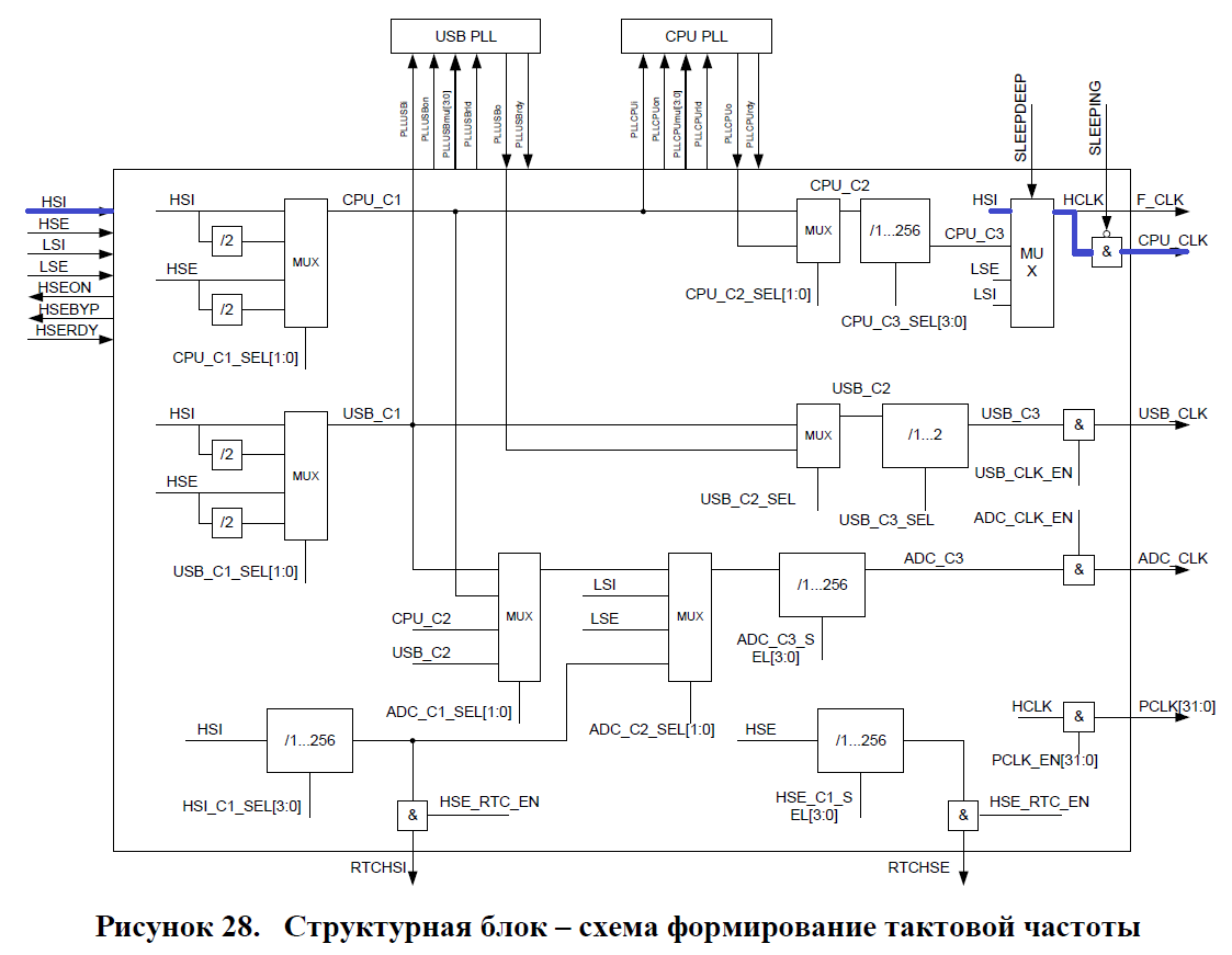
Thus, after switching on, the controller is clocked from HSI. On the block diagram in blue, I highlighted a sequence that demonstrates frequency changes on each block. By default, the frequency source selection module (MUX) is configured to receive with HSI. With the frequency, nothing happens and it, through the HCLK (clocking line, combined with the SysTick timer) gets into the CPU_CLK without changes. But the internal RS generator cannot be called a precise device. Its frequency is very unstable. For this purpose, an external 8 MHz quartz resonator is installed on the board. But what is it called?
HSE external generator
The HSE generator is designed to generate a clock frequency of 2..16 MHz using an external resonator. The generator starts when a UCC power supply appears ...
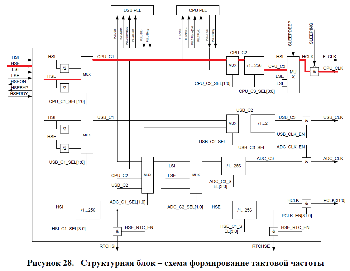
Now we need to understand how to switch the controller from clocking from HSI to HSE. Take another look at the block diagram. In red, I indicated a logical representation of how the signal will travel from the external crystal to the core clock line and the HCLK.
Setting registers clocking.
Now that we have a figurative representation of how clocking “moves”, it's time to deal with clocking registers. The diagram next to each block indicates the bits of certain registers, changing which you can change the "movement" and the clocking frequency. These bits are in the register MDR_RST_CLK-> CPU_CLOCK. I marked in red the bits that need to be changed. Blue can also be left as it is. They are already installed in the correct position.

Next, we need to write define those bits, the values of which we will change.
#define HCLK_SEL(CPU_C3) (1<<8) #define CPU_C1_SEL(HSE) (1<<1) Since all the other bits are zero, we can write to the register directly, without fear of erasing the old data. The result is the following.
RST_CLK->CPU_CLOCK = CPU_C1_SEL(HSE)|HCLK_SEL(CPU_C3); It would seem that everything. But if we sew it up, we get this.
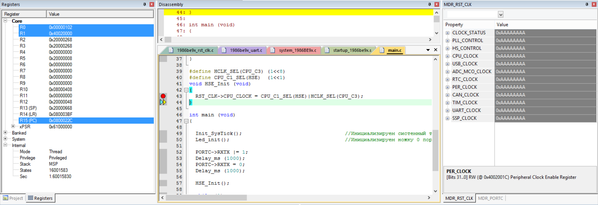
With the subsequent impossibility of debugging. I immediately got into the documentation with error descriptions. But this was not there. As it turned out, I missed one important specific detail. The description of the HSE said:
The HSE generator is designed to generate a clock frequency of 2..16 MHz using an external resonator. The generator starts when a UCC power supply and an HSEON enable signal appear in the HS_CONTROL register.
Take a look at this register.
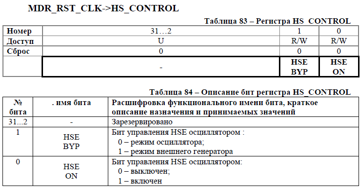
Let's write another 1 define and enable the permission bit.
#define HS_CONTROL(HSE_ON) (1<<0) RST_CLK->HS_CONTROL = HS_CONTROL(HSE_ON); A small digression.
When I was looking for a mistake, I returned to the peripheral clocking page (discussed in the previous article about SysTick ), in which I found RST_CLK. By default it is on, but still I have registered its inclusion before all manipulations with the quartz resonator.
After all the additions, the function was as follows.
#define HCLK_SEL(CPU_C3) (1<<8) #define CPU_C1_SEL(HSE) (1<<1) #define PCLK_EN(RST_CLK) (1<<4) #define HS_CONTROL(HSE_ON) (1<<0) void HSE_Init (void) { RST_CLK->PER_CLOK |= PCLK_EN(RST_CLK); // ( ). RST_CLK->HS_CONTROL = HS_CONTROL(HSE_ON) // HSE . RST_CLK->CPU_CLOCK = CPU_C1_SEL(HSE)|HCLK_SEL(CPU_C3); // "" HSE . } The first "crutch".
At that moment, when I was looking for the error of starting HSE in the list of errors, I came across the next glitch.
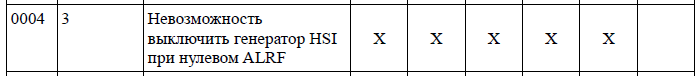
I could not help but remember it, as I had planned to turn off the internal generator immediately after switching on the clock from the external quartz resonator. This error is present in all revisions of the microcontroller. So for her have to sculpt crutch. I will say right away. In my case, I never managed to disable HSI. Despite the fact that I did everything as stated in the recommendations.
We study the problem and the ways of the "solution" in more detail.
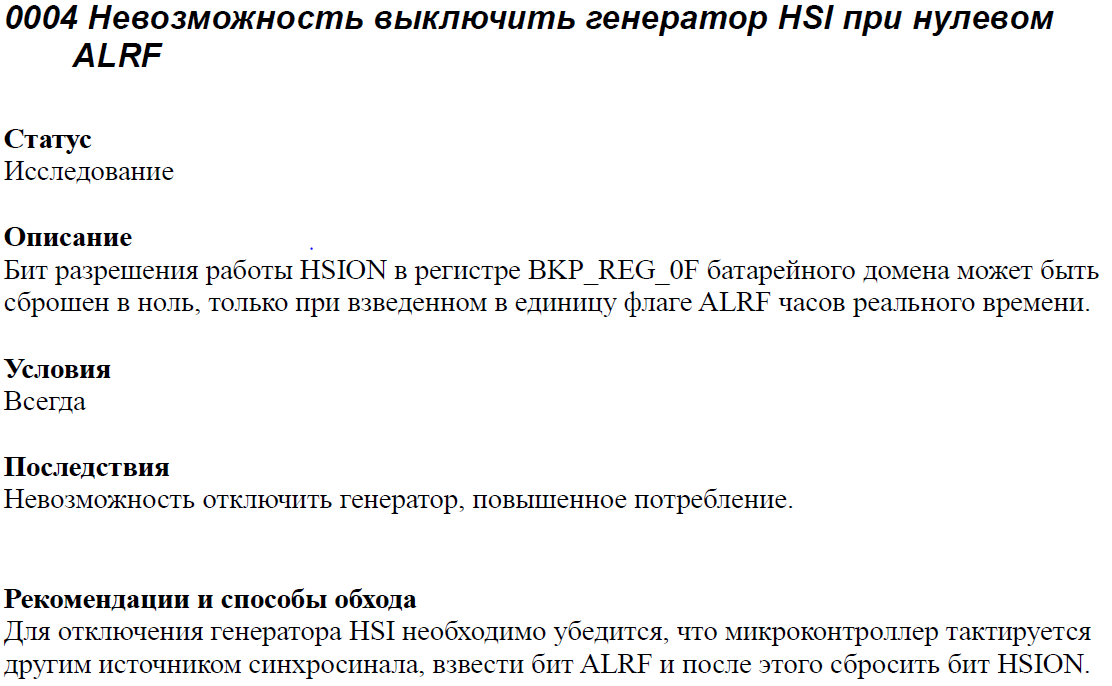
Here is the one mentioned registers.

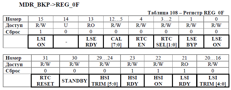
Let's write define for the necessary bits, as well as for clocking the RTC.
#define REG_0F(HSI_ON) ~(1<<22) #define RTC_CS(ALRF) (1<<2) #define PCLK(BKP) (1<<27) And now we will make an attempt to implement it in practice.
#define HCLK_SEL(CPU_C3) (1<<8) #define CPU_C1_SEL(HSE) (1<<1) #define PCLK_EN(RST_CLK) (1<<4) #define HS_CONTROL(HSE_ON) (1<<0) #define REG_0F(HSI_ON) ~(1<<22) #define RTC_CS(ALRF) (1<<2) #define PCLK(BKP) (1<<27) #define CPU_C2_SEL(CPU_C2_SEL) (1<<2) void HSE_Init (void) { RST_CLK->PER_CLOK |= PCLK_EN(RST_CLK); // ( ). RST_CLK->HS_CONTROL = HS_CONTROL(HSE_ON) // HSE . RST_CLK->CPU_CLOCK = CPU_C1_SEL(HSE)|HCLK_SEL(CPU_C3); // "" HSE . RST_CLK->PER_CLOK |= PCLK(BKP); // ( ). BKP->RTC_CS |= RTC_CS(ALRF); // HSI. BKP->REG_0F = BKP->REG_0F&(REG_0F(HSI_ON)); // HSI. } We track the execution of the program. This is the state of the registers before attempting to reset a bit.
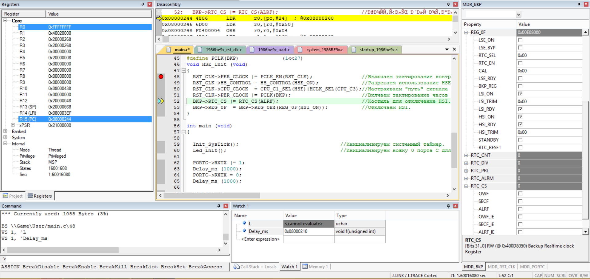
And this after.

At first, I thought that I was wrong with the offset and the millet did not turn on the ALRF bit, but then I clicked on it in the menu on the right (direct sending by registers) and received nothing. I thought that I had not correctly selected the clocking, but by clicking on several other cells I received a response. Apparently, this method does not solve this problem. When trying to turn off the generator by successively pressing ALRF and HSI_ON, we are finally disappointed in the very idea of turning off the generator. Well. It does not interfere much at the initial stage. But in the future it will be problematic. Especially if you make a handheld device.
We receive 16 MHz.
We managed to force our controller to be clocked from an external quartz resonator, which gave us the opportunity to get more accurate time delays. Now it's time to learn how to use the frequency multiplier. In the description of our controller, it is said that it can be clocked with a frequency up to 80 MHz. Let's try to write a function that will allow us to increase the clocking frequency by 2 times. Take another look at the block diagram.
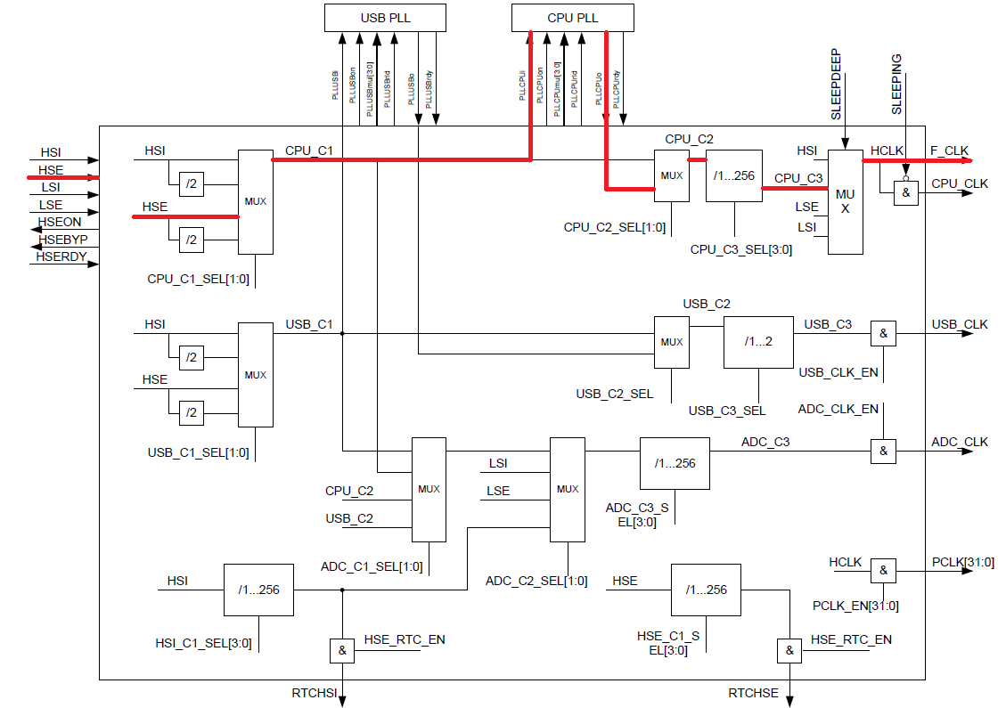
Now, before the frequency "hits" on CPU_C2 on the CPU_C2 line, it passes through the CPU PLL. There it is “multiplied” by some meaning. Consider its registers in more detail.

PLL does not require the clocking bit. So you can immediately start setting up the register. Again, write down the definitions we need.
#define PLL_CONTROL_PLL_CPU_ON (1<<2) //PLL . ')
Well, the very function of the inclusion.
#define PLL_CONTROL_PLL_CPU_ON (1<<2) //PLL . void HSE_16Mhz_Init (void) // " 2 " . { RST_CLK->PLL_CONTROL = PLL_CONTROL_PLL_CPU_ON|(1<<8); // PLL, 2 . RST_CLK->HS_CONTROL = HS_CONTROL(HSE_ON); // HSE . RST_CLK->CPU_CLOCK = CPU_C1_SEL(HSE)|HCLK_SEL(CPU_C3)|CPU_C2_SEL(CPU_C2_SEL) ; // " " HSE . } Now we can add a function to the project.
int main (void) { Init_SysTick(); // . Led_init(); // 0 C . PORTC->RXTX |= 1; Delay_ms (1000); PORTC->RXTX = 0; Delay_ms (1000); HSE_16Mhz_Init(); while (1) { PORTC->RXTX |= 1; Delay_ms (1000); PORTC->RXTX = 0; Delay_ms (1000); } } I want to note that I did not just leave 1 cycle of flashing the LED. This is the so-called "rescue program." If during the experiments something goes wrong, then after pressing RESET there will be a whole second to flash the MK with the corrected firmware.
After flashing, the LED flashes 2 times from the internal quartz, and then 2 times faster from the external one.
Now we optimize our code. Using the function for 3 lines is stupid. Moreover, 2 of them are repeated in the second function. Therefore, I propose to make them define. The first function appears to us in this form.
#define RST_CLK_ON_Clock() RST_CLK->PER_CLOCK |= PCLK_EN(RST_CLK) // ( ). #define HSE_Clock_ON() RST_CLK->HS_CONTROL = HS_CONTROL(HSE_ON) // HSE . #define HSE_Clock_OffPLL() RST_CLK->CPU_CLOCK = CPU_C1_SEL(HSE)|HCLK_SEL(CPU_C3);// "" HSE . And from the second I propose to make a universal frequency switching function. To do this, we remove the HSE setting from the previous function and add another PLL restart bit to the PLL_CONTROL register. So that when a new value is received, immediately start clocking on it. The function begins to have the following form.
#define PLL_CONTROL_PLL_CPU_ON (1<<2) //PLL . #define PLL_CONTROL_PLL_CPU_PLD (1<<3) // PLL. void HSE_PLL (uint8_t PLL_multiply) // " 2 " . { RST_CLK->PLL_CONTROL = RST_CLK->PLL_CONTROL&(~(0xF<<8)); // . RST_CLK->PLL_CONTROL |= PLL_CONTROL_PLL_CPU_ON|((PLL_multiply-1)<<8)|PLL_CONTROL_PLL_CPU_PLD; // PLL X , PLL. RST_CLK->CPU_CLOCK |= HCLK_SEL(CPU_C3)|CPU_C2_SEL(CPU_C2_SEL)|CPU_C1_SEL(HSE); // "" PLL HSE. } Let's put it in our main program. Which also put in order.
void Block (void) // (). { PORTC->RXTX |= 1; Delay_ms (1000); PORTC->RXTX = 0; Delay_ms (1000); } int main (void) { Init_SysTick(); // . Led_init(); // 0 C . Block(); // (). HSE_Clock_ON(); // HSE . HSE_PLL(2); // 2 while (1) { PORTC->RXTX |= 1; Delay_ms (1000); PORTC->RXTX = 0; Delay_ms (1000); } } As a conclusion, we will write a program that, after each cycle, will change the multiplication factor, increasing its speed up to 10, receiving 80 MHz.
void Block (void) // (). { PORTC->RXTX |= 1; Delay_ms (1000); PORTC->RXTX = 0; Delay_ms (1000); } int main (void) { Init_SysTick(); // . Led_init(); // 0 C . Block(); // (). HSE_Clock_ON(); // HSE . HSE_PLL(2); // 2 uint8_t PLL_Data = 1; // . while (1) { PORTC->RXTX |= 1; Delay_ms (1000); PORTC->RXTX = 0; Delay_ms (1000); if (PLL_Data<10) PLL_Data++; else PLL_Data=1; // - . - . HSE_PLL(PLL_Data); } Video of the program.
Recovery fees.
After the first unsuccessful experience with setting the clock frequency, the board stopped responding. Since I did not provide for a defensive program (considering it unnecessary), I began to look for ways to implement it. In the comments to one of the previous articles, vertu77 suggested 3 ways to restore the board in case of incorrect port configuration.
If the JTAG port is still dead - what to do:
1. Then another JTAG port may come in handy. If it is not divorced on the board, you can solder only to the SW legs on another port (less fuss)
2. Upload firmware via UART (regular bootloader)
3. Use the features of the wired program - have time to flash a new fill after energizing before the first blink. In the author's version, this is almost impossible. In real programs, the program is often started from an internal oscillator, then external quartz is initialized. If this uses an endless loop of waiting - you can unsolder the quartz and flash until the first blink.
But in my case, both JTAGs didn’t react (we started when trying to program the MK), there was no protection program, and the USART bootloader was very far away. Yes, and did not want to spend too much time on recovery. So the fourth recovery method was invented. It is necessary to switch BOOT switches to EXT_ROM / JTAG_B mode, connect to JTAG_B and sew a code with firmware that contains a security program. In my case, I just added a wait cycle of one second before tuning the quartz resonator. So after each unsuccessful experience, it was enough to click on the RESET and have time to enter debug mode again.
List of previous articles.
1. We turn from STM32F103 to K1986BE92QI. Or the first acquaintance with the Russian microcontroller.
2. We are switching from STM32 to the Russian K1986BE92QI microcontroller. Setup project in keil and flashing LED.
3. We are switching from STM32 to the Russian K1986BE92QI microcontroller. System Timer (SysTick).
2. We are switching from STM32 to the Russian K1986BE92QI microcontroller. Setup project in keil and flashing LED.
3. We are switching from STM32 to the Russian K1986BE92QI microcontroller. System Timer (SysTick).
Files to projects.
Source: https://habr.com/ru/post/255479/
All Articles