This watch writes time ...
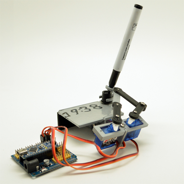
Another crazy weekend work is a real time clock, writing time with a marker.
This idea was spied on the Internet . Distinctive craftsmen and craftsmen from around the world cut out this construction from sheet plastic such as acrylic. Master Keith painted 3D models of all acrylic parts and now this crazy clock can be printed on your 3D printer.
So!
Today you will need:
')
1. MB NANO - Arduino NANO
2. DK NANO - Expansion Board for Arduino Nano and Arduino Pro. It is possible without it, but not very convenient. We'll have to somehow bring power to the servos.
3. Three servos
4. Whiteboard marker
5. Five M3 screws and two nuts.
6. Several parts printed on a 3D printer .
Everything! One Saturday night and your friends will be shocked!
All stl-files and a sketch for Arduino can be downloaded from our site .
Below sketches of all the details.


This is an “assembly” drawing:


Recommendations for the assembly and configuration.
1. Print on a 3D printer all the details from the stl-files
2. The hinges are connected with screws M3, which are freely threaded through a 3.6 mm hole in one piece and screwed as self-tapping screws into a 2.5 mm hole in the second piece. With a small clearance for free rotation. (photo 1)

3. Servos are connected to the Arduino like that. The elevator is 2, the left servomotor is 3, the right servomotor is 4. And this is recorded in the sketch. One could start with the 1st pin, but there is a TX signal. When you turn on and initialize the motor will twitch.

4. When installing servomotors, try to set their axes in the middle position.
5. Pour a sketch into Arduino Nano. It will immediately start working with the << #define CALIBRATION >> calibration mode. (remove or comment out this line after calibration) In this mode, the left and right machine work. Find the line << # define SERVOFAKTOR 620 >>. Changing the value, ensure that the angle between the left and right servos is always 90 degrees when moving. Now find the lines << # define SERVOLEFTNULL 1900 >> and << define SERVORIGHTNULL 984 >>. Changing the values in these lines, make sure that in the far right position the hinges are parallel along the X and Y axes. After that, you can exit the calibration mode. Next, in the sketch, you will find the rows of the marker's elevation height above the table in different << # define LIFT _____ >> modes. Experiment with these values. Get quality erasing and writing. Further in the sketch there are a few more lines with variables in the drawing, you can see what it is, and further adjust the movement. Maybe get a calligraphic underline).
6. Glue a piece of cloth to the cap with double-sided tape.

This idea was spied on the Internet . Distinctive craftsmen and craftsmen from around the world cut out this construction from sheet plastic such as acrylic. Master Keith painted 3D models of all acrylic parts and now this crazy clock can be printed on your 3D printer.
So!
Today you will need:
')
1. MB NANO - Arduino NANO
2. DK NANO - Expansion Board for Arduino Nano and Arduino Pro. It is possible without it, but not very convenient. We'll have to somehow bring power to the servos.
3. Three servos
4. Whiteboard marker
5. Five M3 screws and two nuts.
6. Several parts printed on a 3D printer .
Everything! One Saturday night and your friends will be shocked!
All stl-files and a sketch for Arduino can be downloaded from our site .
Below sketches of all the details.
This is an “assembly” drawing:
Recommendations for the assembly and configuration.
1. Print on a 3D printer all the details from the stl-files
2. The hinges are connected with screws M3, which are freely threaded through a 3.6 mm hole in one piece and screwed as self-tapping screws into a 2.5 mm hole in the second piece. With a small clearance for free rotation. (photo 1)
3. Servos are connected to the Arduino like that. The elevator is 2, the left servomotor is 3, the right servomotor is 4. And this is recorded in the sketch. One could start with the 1st pin, but there is a TX signal. When you turn on and initialize the motor will twitch.
4. When installing servomotors, try to set their axes in the middle position.
5. Pour a sketch into Arduino Nano. It will immediately start working with the << #define CALIBRATION >> calibration mode. (remove or comment out this line after calibration) In this mode, the left and right machine work. Find the line << # define SERVOFAKTOR 620 >>. Changing the value, ensure that the angle between the left and right servos is always 90 degrees when moving. Now find the lines << # define SERVOLEFTNULL 1900 >> and << define SERVORIGHTNULL 984 >>. Changing the values in these lines, make sure that in the far right position the hinges are parallel along the X and Y axes. After that, you can exit the calibration mode. Next, in the sketch, you will find the rows of the marker's elevation height above the table in different << # define LIFT _____ >> modes. Experiment with these values. Get quality erasing and writing. Further in the sketch there are a few more lines with variables in the drawing, you can see what it is, and further adjust the movement. Maybe get a calligraphic underline).
6. Glue a piece of cloth to the cap with double-sided tape.
Source: https://habr.com/ru/post/255465/
All Articles