Electronics for 3D scanner
I'll start with an apology. How a shame it happened! I wanted to assemble the fifth scanner, having corrected all the jambs, to do everything soundly, and here the projects, the USE, the Olympiad ... In general, everything started to turn out, so excuse everyone who was waiting for articles on this topic. For those who are not in the subject, here is the zero article . And those who are in the subject and are still interested, welcome under the cut of the first part. And it will be, as you already understood, about electronics ...
In the process of shirking work on the scanner, more than 10 people wrote to me about how they needed to be helped with the 3D scanner, and most of the questions concerned electronics. About her and will be discussed in this article.
')
What should we do? Firstly, we need to control the stepper motor, secondly, we must at least turn the laser on and off, and thirdly, we must somehow communicate with the computer. Here are the three main tasks that our board must perform. Nothing complicated. That is, we can use almost any microcontroller. I mostly program under STM32, so I took it. Although the general principles of operation will be naturally the same for any controller.
In the third version of the scanner, I took the STM32F030F4 microcontroller. It is distinguished by a more plowable TSSOP20 package (at that time, the boards under LQFP were not working out for me even with a photoresist). Of the things we are interested in - a timer with PWM generation and hardware USART. I think the problems like “Not enough legs for the motor” are not threatened by anyone. Here I got this layout:

But this will be the scheme:

At once I will say that the conductors to the microcontroller are incorrectly drawn in the circuit, but the layout is correct. The numbering of the components on the circuit and on the board is the same, so that the ratings of the components are in the circuit. Not signed only quartz clocking. It is located in the upper left corner of the board. By the way, capacitors to it are not necessarily 10 pF. Their value should be in the range of 5 to 20 pF.
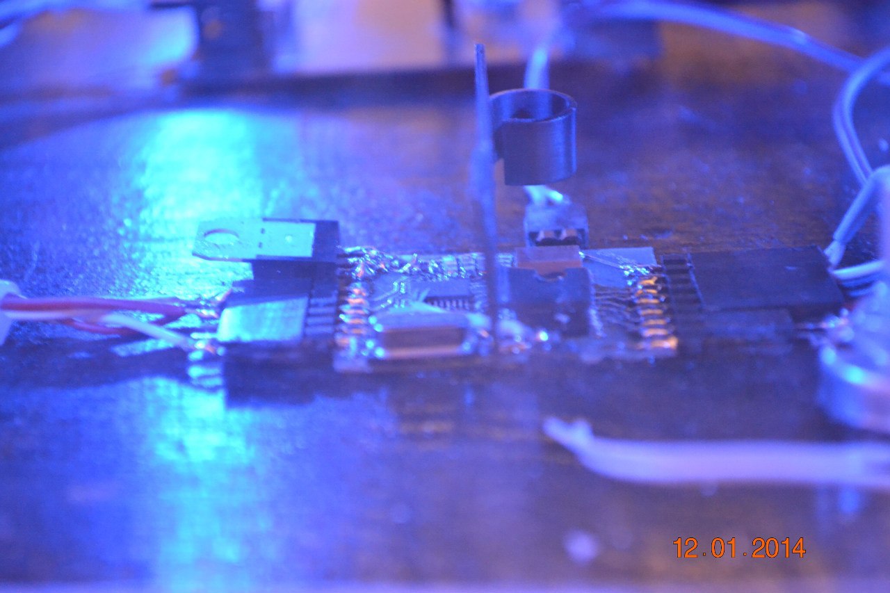
You may notice that there are no holes for the PLS pins on the wiring. I just solder them sideways. This can be seen in the very first photo at the beginning of the article. Also on the layout you can see that in red I combined these pins into groups (G1, G2, etc.).
G1 is a connector for communicating with a computer. From left to right: GND, SWDIO, SWCLK, RX, TX, + 5V.
G2 - power for the laser. Plus bottom.
G3 - laser connection. Plus to the left (your cap).
G4 - motor connection.
As you can guess from the scheme - we are driving exactly the unipolar stepping motor. For this, field effect transistors are used. I liked the idea to install SMD assembly. I applied these assemblies here . You can take any others. The main condition is the compatibility of the cases (not that the legs of both those and those 8, but that the pinout coincides). Well, also the fact that transistors must be N-channel.
For the laser made a separate voltage regulator (lower left corner of the circuit). This allows you to adjust the laser power by adjusting the output voltage of the stabilizer. To do this, you need to change the resistance of the resistor R5. Therefore, as the R5 is best to install a potentiometer. The attentive reader will ask: "Why 9V?". In general, because the laser must be powered separately from the motor. The motor is an inductive load, which means it creates voltage surges that can kill a laser diode. Powering from 5V will not work due to the fact that the voltage drop on the stabilizer is large enough and we may simply not have enough voltage for its normal operation. Therefore, I put the power supply on 9V, because I already had it and it fit perfectly on the voltage. The stabilizer is installed on the radiator, but not soldered to the board. Instead, it plugs into connector G2.
ATTENTION! This circuit is not a laser diode driver! It connects to it and adjusts the supply voltage. That is, if you have assembled the laser yourself, then at least you will have to supply a current-limiting resistor and a capacitor.
In general, for all circuitry. The board is easily manufactured by LUT. Here is a link to the layout in SprintLayout .
There are no photos, no schemes: everything was assembled on a breadboard (breadbord). The microcontroller took the STM32F401RE. No, this power is certainly not needed. Simply, it is installed in the STM32F401-Nucleo. I liked this board because it has not only pins, but also sockets (as in the Arduino), and also the fact that it has ST-Link V2.1 installed on it. What good is it? And the fact that in addition to the programmer there is also a USB-> UART adapter. This means that there will be less wires and fewer boards. Of the minuses can be noted that it is defined in the system as a flash drive, so it constantly pops up "Explorer" in Windows. But it is so. Little things. Better than wires. The scheme basically remains the same. Three chips can be replaced with one ULN (ULN200x; x = 1,2,3,4). True, the transistors there are designed for less current and generally bipolar, but the body is one.
But about the control of the laser must be said separately. In the fourth version, I decided to make the power adjustable by software. In the sense we can adjust the power of the UART. To control the laser power chime PWM on the TDA2030. The scheme of this block will be as follows:

Innon- human language, it is a non-inverting repeater on an op amp. It is needed to amplify the current . It can be given any power from 5 to 18V - the repeater repeats not only the shape but also the amplitude of the signal (only the current is amplified), so there is nothing to worry about. Is that the fact that the output voltage STM32 maximum voltage will be 3.3V. So, we cannot squeeze out full power from lasers powered by Li-ion batteries - their maximum voltage is 4.2V. But just do not burn for a software error. The filter at the output of such an amplifier is better to install, of course, but often there is a filtering capacitor in lasers, so the choice is yours.
ATTENTION! If you suddenly decided to make a full-fledged amplifier, and not a repeater, then remember that we control it with the help of PWM, which means that the voltage will jump from the minimum value to the maximum. The laser diode needs quite a bit of time to burn, so if the voltage exceeds the maximum 4.2V (even briefly), then the diode will burn!
There are many boards for controlling motors in RepRap 3D printers. For example such . Such boards are easily searched for by the chip name. So what is she good at? Firstly, it can control bipolar motors, and any unipolar cell turns into a bipolar by banal disconnection of the middle winding taps (or rather, their non-connection). Secondly, it is easily controlled: one pin sets the direction, and the second we give impulses. Every impulse is a step. And the last feature is the division of steps (mikroshag). That is, the chip can take not a full step, but for example 1/2. Not 5 degrees, as a previous scanner would have done, but 2.5. And this is not the limit! It supports division by 16. But in fact it is not necessary.
So highly recommend for use. Saves time, legs (microcontroller of course), but not money. But it is worth it.
I would rather solder the control board for the same STM32F030, because it is cheap and small. Although the latter does not play a role in such a huge box, it may be a minus for some people.
In the management of the laser is nothing special to change. Everything worked so well on the fourth scanner, and there is no point in changing anything. Is that the DAC screw, but it is rather an extra pain in the head.
And now print, poison, solder and cod, cod, cod! But about the code in the next article. And this time I will not be allowed to score. I hope for most of the questions on electronics, I answered. It seems there is nothing particularly complicated and frightening. I will try to write about the code as soon as possible (throwing out all indecent comments and deleting broken and unnecessary pieces).
Good luck to everyone with projects / diplomas / get-togethers in the garage where this article came in handy!
PS In the diagram, a typo - capacitors near quartz - 10 pF, not 10 nF.
In the process of shirking work on the scanner, more than 10 people wrote to me about how they needed to be helped with the 3D scanner, and most of the questions concerned electronics. About her and will be discussed in this article.
')
General idea
What should we do? Firstly, we need to control the stepper motor, secondly, we must at least turn the laser on and off, and thirdly, we must somehow communicate with the computer. Here are the three main tasks that our board must perform. Nothing complicated. That is, we can use almost any microcontroller. I mostly program under STM32, so I took it. Although the general principles of operation will be naturally the same for any controller.
Third version
In the third version of the scanner, I took the STM32F030F4 microcontroller. It is distinguished by a more plowable TSSOP20 package (at that time, the boards under LQFP were not working out for me even with a photoresist). Of the things we are interested in - a timer with PWM generation and hardware USART. I think the problems like “Not enough legs for the motor” are not threatened by anyone. Here I got this layout:
But this will be the scheme:
At once I will say that the conductors to the microcontroller are incorrectly drawn in the circuit, but the layout is correct. The numbering of the components on the circuit and on the board is the same, so that the ratings of the components are in the circuit. Not signed only quartz clocking. It is located in the upper left corner of the board. By the way, capacitors to it are not necessarily 10 pF. Their value should be in the range of 5 to 20 pF.
You may notice that there are no holes for the PLS pins on the wiring. I just solder them sideways. This can be seen in the very first photo at the beginning of the article. Also on the layout you can see that in red I combined these pins into groups (G1, G2, etc.).
G1 is a connector for communicating with a computer. From left to right: GND, SWDIO, SWCLK, RX, TX, + 5V.
G2 - power for the laser. Plus bottom.
G3 - laser connection. Plus to the left (your cap).
G4 - motor connection.
As you can guess from the scheme - we are driving exactly the unipolar stepping motor. For this, field effect transistors are used. I liked the idea to install SMD assembly. I applied these assemblies here . You can take any others. The main condition is the compatibility of the cases (not that the legs of both those and those 8, but that the pinout coincides). Well, also the fact that transistors must be N-channel.
For the laser made a separate voltage regulator (lower left corner of the circuit). This allows you to adjust the laser power by adjusting the output voltage of the stabilizer. To do this, you need to change the resistance of the resistor R5. Therefore, as the R5 is best to install a potentiometer. The attentive reader will ask: "Why 9V?". In general, because the laser must be powered separately from the motor. The motor is an inductive load, which means it creates voltage surges that can kill a laser diode. Powering from 5V will not work due to the fact that the voltage drop on the stabilizer is large enough and we may simply not have enough voltage for its normal operation. Therefore, I put the power supply on 9V, because I already had it and it fit perfectly on the voltage. The stabilizer is installed on the radiator, but not soldered to the board. Instead, it plugs into connector G2.
ATTENTION! This circuit is not a laser diode driver! It connects to it and adjusts the supply voltage. That is, if you have assembled the laser yourself, then at least you will have to supply a current-limiting resistor and a capacitor.
In general, for all circuitry. The board is easily manufactured by LUT. Here is a link to the layout in SprintLayout .
Fourth scanner
There are no photos, no schemes: everything was assembled on a breadboard (breadbord). The microcontroller took the STM32F401RE. No, this power is certainly not needed. Simply, it is installed in the STM32F401-Nucleo. I liked this board because it has not only pins, but also sockets (as in the Arduino), and also the fact that it has ST-Link V2.1 installed on it. What good is it? And the fact that in addition to the programmer there is also a USB-> UART adapter. This means that there will be less wires and fewer boards. Of the minuses can be noted that it is defined in the system as a flash drive, so it constantly pops up "Explorer" in Windows. But it is so. Little things. Better than wires. The scheme basically remains the same. Three chips can be replaced with one ULN (ULN200x; x = 1,2,3,4). True, the transistors there are designed for less current and generally bipolar, but the body is one.
But about the control of the laser must be said separately. In the fourth version, I decided to make the power adjustable by software. In the sense we can adjust the power of the UART. To control the laser power chime PWM on the TDA2030. The scheme of this block will be as follows:
In
ATTENTION! If you suddenly decided to make a full-fledged amplifier, and not a repeater, then remember that we control it with the help of PWM, which means that the voltage will jump from the minimum value to the maximum. The laser diode needs quite a bit of time to burn, so if the voltage exceeds the maximum 4.2V (even briefly), then the diode will burn!
How to do better?
There are many boards for controlling motors in RepRap 3D printers. For example such . Such boards are easily searched for by the chip name. So what is she good at? Firstly, it can control bipolar motors, and any unipolar cell turns into a bipolar by banal disconnection of the middle winding taps (or rather, their non-connection). Secondly, it is easily controlled: one pin sets the direction, and the second we give impulses. Every impulse is a step. And the last feature is the division of steps (mikroshag). That is, the chip can take not a full step, but for example 1/2. Not 5 degrees, as a previous scanner would have done, but 2.5. And this is not the limit! It supports division by 16. But in fact it is not necessary.
So highly recommend for use. Saves time, legs (microcontroller of course), but not money. But it is worth it.
I would rather solder the control board for the same STM32F030, because it is cheap and small. Although the latter does not play a role in such a huge box, it may be a minus for some people.
In the management of the laser is nothing special to change. Everything worked so well on the fourth scanner, and there is no point in changing anything. Is that the DAC screw, but it is rather an extra pain in the head.
And now what?
And now print, poison, solder and cod, cod, cod! But about the code in the next article. And this time I will not be allowed to score. I hope for most of the questions on electronics, I answered. It seems there is nothing particularly complicated and frightening. I will try to write about the code as soon as possible (throwing out all indecent comments and deleting broken and unnecessary pieces).
Good luck to everyone with projects / diplomas / get-togethers in the garage where this article came in handy!
PS In the diagram, a typo - capacitors near quartz - 10 pF, not 10 nF.
Source: https://habr.com/ru/post/255371/
All Articles