Multifunctional temperature / humidity sensor on the ESP8266 or one more step to the “Internet of things”
Disclaimer: this article may contain errors, since I recently worked with the ESP8266 module and still do not fully understand many of the architectural aspects of this device.
Today, practically in any home there is a Wi-Fi router and it would be short-sighted not to use this device for home automation, especially since today there are all available equipment on the market for the implementation of any ideas. Below is the option to create a small electronic device, which is a platform for building various sensors / actuators based on the Wi-Fi module - ESP8266.
This module is well described here , here , and on this site you will find everything that mankind knows about the ESP8266 module.
')
So, what should be able to "device":
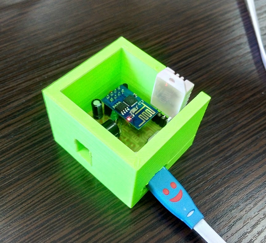
Device layout:
There are a lot of modifications of the ESP8266 module (the options are here ), but, in principle, they differ only in size, type of antenna and number of available I / O ports. I used the ESP8266 ESP-01 module:
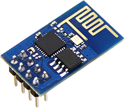
It has only two ports (excluding USART) - GPIO0, GPIO2, but for my purposes it is enough, one port is for the sensor and the second is for load control.
The USB interface is implemented by a CH340G USB-USART converter.

It describes its connection to 3.3 and 5V logic. The chip is very cheap and convenient to use. From the strapping only a crystal oscillator at 12MHz and a pair of capacitors. As a result, you have on the one hand USART, and on the other - USB. On the PC, the device is displayed as a virtual serial port.
To control the load, I used a pair of transistor switches. Why so - thehardened electronic engineer will be asked by the attentive reader. The thing is that the supply voltage can be different, but I wanted the relay to be controlled by voltage = supply voltage. When using a pnp transistor, the emitter current (at the supply voltage> voltage of the ESP8266 module) goes to the module, which is not good at all. I could not use only the npn transistor, since then the GPIO0 port would be pulled to the minus all the time, and in this case the module will enter the programming mode every time we restart the module. So, by connecting pnp + npn transistors, I control the minus of the relay.
DHT22 sensor:
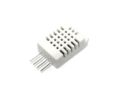
Does not require any additional strapping and connects directly to the ESP module. He needs only one port for data exchange (interface like 1-wire).
Also on the diagram:
The device is powered 5 - 12V.
Now let's talk about the software.
There is such a project NodeMCU . In my opinion, very cool stuff. A small OS that can execute your lua scripts directly on ESP8266. NodeMCU can work with a bunch of protocols out of the box, it can raise a web server, create a TCP connection ...
At the beginning of the firmware in our module NodeMCU. Instructions on firmware .
After the module is flashed, you can download our scripts. There are many ways, but personally I like the ESPlorer utility - a very handy software not only for downloading scripts, but also for developing debugging scripts.
Now in more detail. We need to fill three scripts:
There is a nuance here. Unfortunately, the external flash memory of the module is not enough to load the NodeMCU and my scripts, so I use the following “crutch” solution: load one script, execute the node.compile command (“dht22.lua”) - this command compiles the script into “dht22. lc ”, as a result, it takes up less space in both flash memory and RAM, as later NodeMCU will load it into memory during the execution of the main script. Then we delete the uncompiled script with the file.remove command (“dht22.lua”). We perform the same manipulations with main.lua. Last we load the init.lua script, we no longer compile it. Restart module.
At the start, NodeMCU will execute the “init.lua” script, which in turn will launch “main.lua”. The "main.lua" script will connect to the network, send data to the COM port and network to the specified broker mqtt.
More details on the scripts will answer in the comments.
Well, everything seems to be. If the topic is interesting, in the next article I will tell you about the mqtt broker and the connection of this whole business to Openhab.
Thanks for attention.
Today, practically in any home there is a Wi-Fi router and it would be short-sighted not to use this device for home automation, especially since today there are all available equipment on the market for the implementation of any ideas. Below is the option to create a small electronic device, which is a platform for building various sensors / actuators based on the Wi-Fi module - ESP8266.
This module is well described here , here , and on this site you will find everything that mankind knows about the ESP8266 module.
')
So, what should be able to "device":
- Receive data from a humidity / temperature sensor DHT22 ;
- Control solid-state relay (for example SSR-25 DA );
- Connect to a Wi-Fi router with a given login and password;
- Transmit and receive data through an MQTT broker;
- Connect via USB for debugging and firmware.
Device layout:
There are a lot of modifications of the ESP8266 module (the options are here ), but, in principle, they differ only in size, type of antenna and number of available I / O ports. I used the ESP8266 ESP-01 module:
It has only two ports (excluding USART) - GPIO0, GPIO2, but for my purposes it is enough, one port is for the sensor and the second is for load control.
The USB interface is implemented by a CH340G USB-USART converter.
It describes its connection to 3.3 and 5V logic. The chip is very cheap and convenient to use. From the strapping only a crystal oscillator at 12MHz and a pair of capacitors. As a result, you have on the one hand USART, and on the other - USB. On the PC, the device is displayed as a virtual serial port.
To control the load, I used a pair of transistor switches. Why so - the
DHT22 sensor:
Does not require any additional strapping and connects directly to the ESP module. He needs only one port for data exchange (interface like 1-wire).
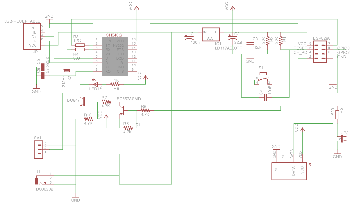
Also on the diagram:
- Jumper JP2 - for firmware module. Jumper pulls up GPIO0 to a minus. In operating mode - open, during firmware - closed);
- S1 button - reset module;
- SV1 connector - relay connection;
- J1 connector - power socket;
- Connector JP1 - micro USB mom.
The device is powered 5 - 12V.
Now let's talk about the software.
There is such a project NodeMCU . In my opinion, very cool stuff. A small OS that can execute your lua scripts directly on ESP8266. NodeMCU can work with a bunch of protocols out of the box, it can raise a web server, create a TCP connection ...
At the beginning of the firmware in our module NodeMCU. Instructions on firmware .
After the module is flashed, you can download our scripts. There are many ways, but personally I like the ESPlorer utility - a very handy software not only for downloading scripts, but also for developing debugging scripts.
Now in more detail. We need to fill three scripts:
dht22.lua - the actual module reading data from the DHT22 sensor
- ************************************************* **************************
- DHT22 module for ESP8266 with nodeMCU
- - Written by Javier Yanez
- but based on a script of Pigs Fly from ESP8266.com forum
- - MIT license, opensource.org/licenses/MIT
- ************************************************* **************************
local moduleName = ...
local M = {}
_G [moduleName] = M
local humidity
local temperature
function M.read (pin)
local checksum
local checksumTest
humidity = 0
temperature = 0
checksum = 0
- Use Markus Gritsch trick to speed up read / write on GPIO
local gpio_read = gpio.read
local bitStream = {}
for j = 1, 40, 1 do
bitStream [j] = 0
end
local bitlength = 0
- Step 1: send out start signal to DHT22
gpio.mode (pin, gpio.OUTPUT)
gpio.write (pin, gpio.HIGH)
tmr.delay (100)
gpio.write (pin, gpio.LOW)
tmr.delay (20000)
gpio.write (pin, gpio.HIGH)
gpio.mode (pin, gpio.INPUT)
- Step 2: DHT22 send response signal
- bother with bus timeout
while (gpio_read (pin) == 0) do end
local c = 0
while (gpio_read (pin) == 1 and c <500) do c = c + 1 end
- bother with bus timeout
while (gpio_read (pin) == 0) do end
c = 0
while (gpio_read (pin) == 1 and c <500) do c = c + 1 end
- Step 3: DHT22 send data
for j = 1, 40, 1 do
while (gpio_read (pin) == 1 and bitlength <10) do
bitlength = bitlength + 1
end
bitStream [j] = bitlength
bitlength = 0
- bother with bus timeout
while (gpio_read (pin) == 0) do end
end
--DHT dataized, process.
for i = 1, 16, 1 do
if (bitStream [i]> 3) then
humidity = humidity + 2 ^ (16 - i)
end
end
for i = 1, 16, 1 do
if (bitStream [i + 16]> 3) then
temperature = temperature + 2 ^ (16 - i)
end
end
for i = 1, 8, 1 do
if (bitStream [i + 32]> 3) then
checksum = checksum + 2 ^ (8 - i)
end
end
checksumTest = (bit.band (humidity, 0xFF) + bit.rshift (humidity, 8) + bit.band (temperature, 0xFF) + bit.rshift (temperature, 8))
checksumTest = bit.band (checksumTest, 0xFF)
if temperature> 0x8000 then
- convert to negative format
temperature = - (temperature - 0x8000)
end
- conditions compatible
if (checksumTest - checksum> = 1) or (checksum - checksumTest> = 1) then
humidity = nil
end
end
function M.getTemperature ()
return temperature
end
function M.getHumidity ()
return humidity
end
return M
main.lua - the main script, connects to the Wi-Fi network, receives data, sends them via mqtt and manages the load
function subscribe ()
m: subscribe ("/ myhome /" .. id .. "/ light", 0, function (conn) print ("Subscribe success") end)
m: on ("message", function (conn, topic, data)
print (topic ... ":" ..data)
if data == "ON" then gpio.write (3, gpio.LOW) end
if data == "OFF" then gpio.write (3, gpio.HIGH) end
end)
end
function dht22_get_data ()
dht22 = require ("dht22")
dht22.read (4)
local t = dht22.getTemperature ()
local h = dht22.getHumidity ()
if t ~ = nil then
t = ((t- (t% 10)) / 10) .. "." .. string.format ("%. i", (t% 10))
else t = nil
end
if h ~ = nil then
h = ((h- (h% 10)) / 10) .. "." .. string.format ("%. i", (h% 10))
else h = nil
end
dht22 = nil
package.loaded ["dht22"] = nil
collectgarbage ()
return t, h
end
function post_data ()
t, h = dht22_get_data ()
if t ~ = nil then
m: publish ("/ myhome /" .. id .. "/ temperature", t, 0,0, function ()
print ("Temperature" ..t)
if h ~ = nil then
m: publish ("/ myhome /" .. id .. "/ humidity", h, 0.0, function () print ("Humidity" ..h) end)
end
end)
end
end
function init_network ()
collectgarbage ()
print (id)
if wifi.sta.status () ~ = 5 then
print ("Reconnecting WIFI")
wifi.setmode (wifi.STATION)
wifi.sta.config ("Login", "password")
wifi.sta.connect ()
tmr.alarm (0.5000.0, function () init_network () end)
else
print ("IP:" ..wifi.sta.getip ())
print ("Connecting to MQTT server")
tmr.alarm (0.7000.0, function () init_network () end)
if m ~ = nil then
m: close ()
end
m = mqtt.Client (id, 120)
m: connect ("192.168.0.x", 1883.0, function (conn)
tmr.stop (0)
print ("Connected")
subscribe ()
tmr.alarm (0, 60000, 1, function () post_data () end)
m: on ("offline", function (con)
print ("offline.Reconnecting")
init_network ()
end)
end)
end
end
gpio.mode (3, gpio.OUTPUT)
id = "esp _" .. wifi.sta.getmac ()
init_network ()
init.lua - start script. Its first starts NodeMCU at the start.
print ("ESP8266_home_board_v_x.x")
dofile ('main.lc')
dofile ('main.lc')
There is a nuance here. Unfortunately, the external flash memory of the module is not enough to load the NodeMCU and my scripts, so I use the following “crutch” solution: load one script, execute the node.compile command (“dht22.lua”) - this command compiles the script into “dht22. lc ”, as a result, it takes up less space in both flash memory and RAM, as later NodeMCU will load it into memory during the execution of the main script. Then we delete the uncompiled script with the file.remove command (“dht22.lua”). We perform the same manipulations with main.lua. Last we load the init.lua script, we no longer compile it. Restart module.
At the start, NodeMCU will execute the “init.lua” script, which in turn will launch “main.lua”. The "main.lua" script will connect to the network, send data to the COM port and network to the specified broker mqtt.
More details on the scripts will answer in the comments.
Well, everything seems to be. If the topic is interesting, in the next article I will tell you about the mqtt broker and the connection of this whole business to Openhab.
Thanks for attention.
Source: https://habr.com/ru/post/255359/
All Articles