Hardware room (about satellite network infrastructure and oscilloscope)
In the last post, I showed how the satellite earth station looks like outside . Now let's take a little look at the theory, plus go down to the hardware room. The IF cables we saw in the containers come here. Well, or leave here, we have the same "reception" and "transfer".

It all starts and ends with the antenna:
')

The antenna, besides, in fact, the mirror and the irradiating system, incorporates waveguide paths, LNA and (optionally) auto-tracking system, anti-icing, drying of the waveguide path. Caution traffic .
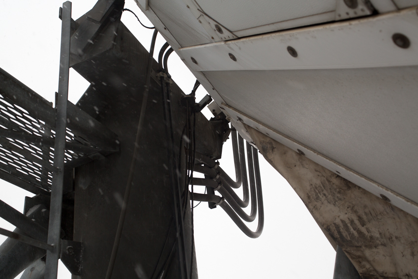
The radio equipment is located in the immediate vicinity of the antenna: transmitters (microwave power amplifiers), converters, active equipment redundancy systems, and auto-tracking and anti-icing controllers. Between the radio equipment on the roof and the modems in the equipment room are “IF signals” (intermediate frequency, low 70/140 MHz, or L-Band 1 GHz). The frequency converter is supplied via cables or with the use of special “frequency converter via optics” devices.
So let's go over what and how it works here in the form of a short FAQ.
- What kind of data is transmitted most often?
Since VimpelCom is better known as a cellular operator, it is not surprising that a significant part of the traffic is exactly the traffic of the mobile network. Nevertheless, a very substantial part of the traffic is “non-mobile” traffic: corporate networks, trunk voice, Internet. If we take not the ownership of the traffic, but its type, then we are not unique here: a significant part of the traffic is data, including the same Internet. As, however, and on any other modern communication network.
- How many satellites use the network?
We have one of the largest satellite networks in Russia, when viewed in terms of the overall speed of the channels. And for her work now used a dozen satellites, scattered in an arc from 57 to 183 degrees east longitude. For the inquisitive: 183 degrees east longitude - yes, in fact it is already 3 degrees west. But the satellite has a "service area" in the eastern hemisphere, and therefore it is listed behind this hemisphere.
- Why do you need such a large antenna mirror?
Actually, this is a topic for a separate article entitled “The Power of Satellite Lines”. But if it is short, then this: the larger the diameter of the mirror, the narrower the beam forms the antenna. And the more energy goes precisely into this beam, and does not fly apart in all directions. An ordinary pocket flashlight: the larger the reflector of a light bulb, the further such a flashlight will be beaten. It's all the same. Why is this necessary and why it is impossible to simply put the “light bulb” (i.e., the transmitter in our case) more powerful? Can. But at the same time you will improve energy only on the line "Earth - space". And the signal sent by the satellite back, you still have to manage to catch. And if on the receiving side you have a small antenna, then to get the required signal-to-noise ratio at the receiver input you will take more energy (resources if you want) from the satellite. And the onboard resource is the most expensive in the whole scheme. For illustration, a diagram from the legendary reference book Satellite Communications and Broadcasting, edited by (no less legendary) L. Ya. Kantor:
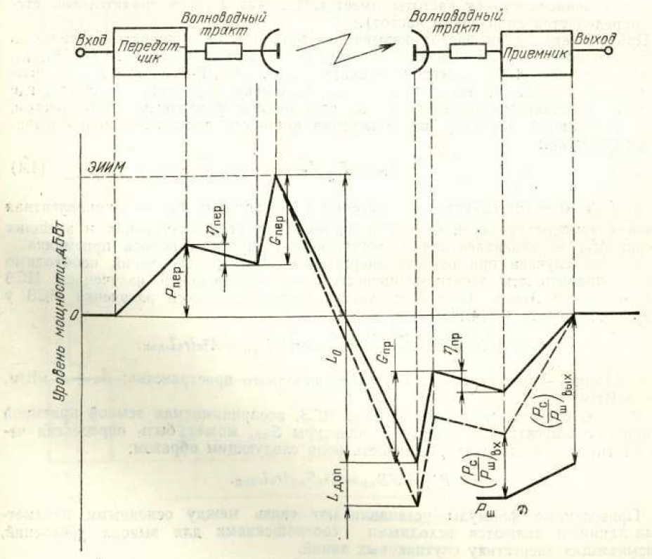
All that is up is the gain / gain of the signal; all that down is loss / attenuation. See bursts up near each of the antennas? This is precisely the gain in the power industry, which is the greater, the larger the diameter of the antenna. Attentive: the diagram shows only one span: "Earth - space" or "space - Earth" (optional). But for the second span - all the same. Antenna gain also depends on the frequency range in which it operates. And the higher the frequency, the greater the gain. Therefore, an antenna with a diameter of 3.5 m, operating in the Ku band (11/14 GHz), has approximately the same gain as the 7 m antenna operating in the C band (4/6 GHz). Now it is clear why the overwhelming majority of direct television systems use the Ku band in particular?
- What is the minimum size of the reflector? Why are there less cymbals on television?
According to the experience of the expedition to the North Pole: they are abnormal, they can. Any system is calculated to solve a specific problem. And this solution should be as efficient as possible, including from a financial point of view. Yes, a small antenna is inefficient from an energy point of view and requires a larger satellite resource for transmitting a channel. Accordingly, such a channel turns out to be much more expensive. But ... How long does the reporting station work? A few tens of minutes (compare with the standard "signalist" 24x7x365). And in general, try to quickly deploy an antenna of several meters in diameter on a busy street. Definitely, this will be a show, which, perhaps, will generally distract attention from the main event of the report. In addition, for transmitting stations, there are still restrictions on the minimum size of the mirror and the maximum transmitter power. The reason is simple: if the diagram is very wide, then even if the antenna is properly tuned, not only the desired satellite, but also the neighboring ones, are included in the antenna diagram. If at the same time the transmitter of such a station is powerful enough, then it will easily illuminate the neighboring satellites, interfering with the channels / services operating there.
- What you need to know about the ranges and polarization on the fingers?
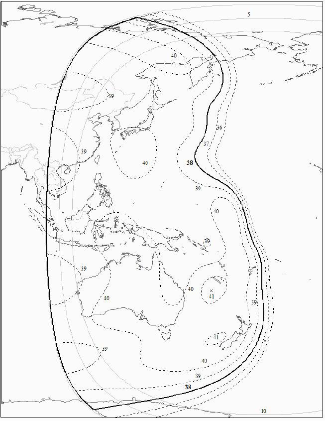
The most common are two frequency bands: C (middle frequency up, on the Earth-to-space line around 6 GHz, down frequency - 4 GHz) and Ku (14 GHz up, 11 GHz down). The entire available band on the satellite is divided into transponders (or trunks), spaced apart by frequency. For simplicity, we can assume that the transponder is a set of a receiver, a frequency converter, which carries the signal from frequency up to frequency down, and a transmitter tuned to a specific frequency range. And there are several such transponders on the satellite (several dozen if we are talking about modern “heavy” satellites). To be able to use the same frequency twice the signal is divided by polarization. In C, circular (right and left) polarization is usually used, in Ku, linear (horizontal and vertical) polarization is used. As a result, the frequency-polarization distribution of transponders on a satellite looks like this:

Above - satellite reception of signals from the Earth, below - transmission to the Earth. The center frequencies of the transponders are indicated, and their conditional numbers. Inside each of the transponders are organized channels. Which and how much - depends on energy, the type of system used, the required channel band (s), and most importantly - the need for channels and the money available to the operator.
- Why is the uplink frequency always higher than the downlink frequency? And why are the frequencies different at all?
The higher the frequency, the harder it is to amplify. And the less efficiency has such an amplifier (in terms of output power, power consumption, weight and size characteristics). It is clear that with equal power output to the satellite you will put the amplifier, which is smaller in weight, consumes less energy and produces less heat. And it will be an amplifier operating at a lower frequency. And the frequencies are different because in a small volume (and very closely within the satellite) it is impossible to provide a large gain factor at one frequency. Attempting to do this will lead to self-excitation of the amplifier. Using different frequencies for receiving and transmitting, we divide the entire amplifier path of the satellite in half. And for each of the halves, the problem becomes quite solvable.
- What is the voice path from the satellite subscriber to the subscriber in France? Which nodes pass the data?
From the phone to the base station, from the base station to the satellite communications station, then to the satellite, from it to the central station, which is paired with this (Khabarovsk, Krasnoyarsk, Moscow ...). Further the channel with a call comes to the zonal switch. And if the BS is Ural, and the channel lands in Moscow, then it will have to go back to the Urals - this is what the GSM / 3G network operation protocol requires. The switch unpacks the data, extracts the call from them. And then - the same as in a standard PBX: by the number you can see where to send this call further (in this example - to France). Again in the highway to Moscow, in Moscow - in the "intercity", to the switch in France, there - to the called subscriber.
What is most funny, the Internet in GSM / 3G goes on the same principle. Irrational? Yes, but these are the requirements of the standards and architecture of GSM / 3G networks: dura lex sed lex. And dual use of the land highway is not the saddest thing. It is much sadder when a satellite BS connects to its switch, which, in turn, also has an uplink via satellite. And such a situation arises in almost all major cities that do not have access to the outside world through land channels (already mentioned Anadyr, Magadan, Kamchatka). In this case, the call (or data) of the subscriber goes through "two jumps". And this is not only double the cost, but double delays. But this is life, and everything can be used to - even to a conversation with a delay of 1.5 seconds. I note that in LTE networks, data transfer is organized more efficiently.
- How to determine where to “land” the signal if the satellite is visible from Khabarovsk and Irkutsk?
If the source of traffic (or, on the contrary, its final consumer) is located, for example, in Moscow, then, naturally, it is better to choose Irkutsk, having played for this about 50 ms delay. Due to the fact that we have a large network, many possible landing points, our own land lines and many satellites - for each case, you can choose the best option. Not so long ago, Intelsat presented its innovative scheme for the landing of user channels - Intelsat One . And we have been doing this for at least ten years, and without much noise.
For now. The next part is not so romantic - we go down to the control room and see why an engineer in the twenty-first century needs an oscilloscope, and at the same time we will carefully examine the signal path further.
We descend from a cold high roof into a warm cozy hardware room . It is located in a fairly large room, where not only “purely satellite” equipment is installed, but also a lot more: channel and channel-forming equipment, PBX, optical and copper crosses, low-voltage power systems and their batteries. And, of course, air-conditioning and air conditioning systems. And this is not the only hardware located in this building.
At the entrance, as required by the rules of good tone, you need to pass the wave and wipe the feet. To speed up the latter, a special sticky pad was made, which carefully takes away all the dirt remaining after the mat:

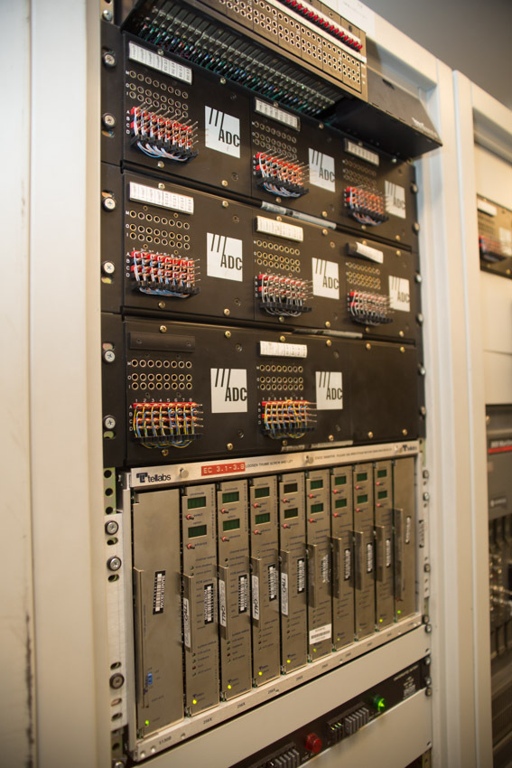
IF cables from containers come in a separate rack. Here they are, find out?
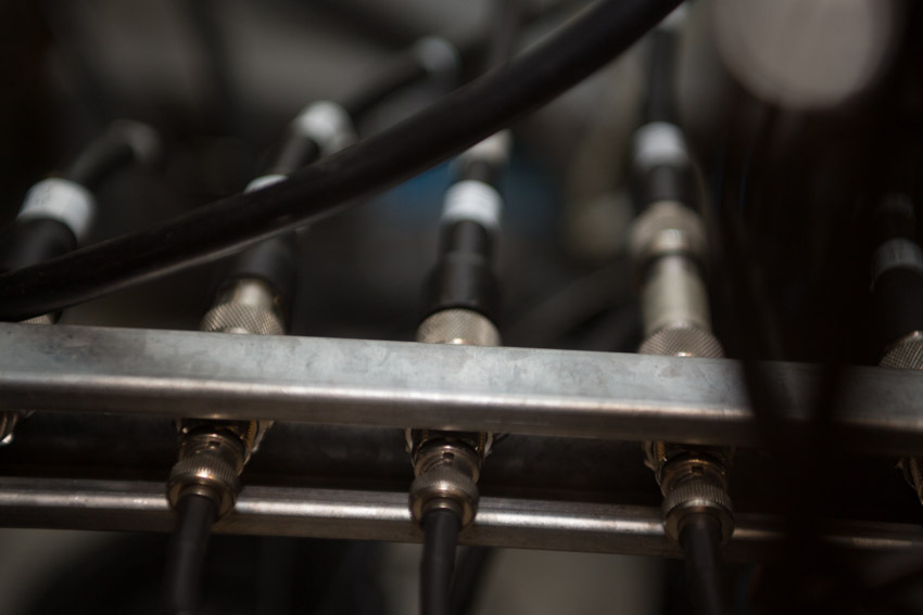
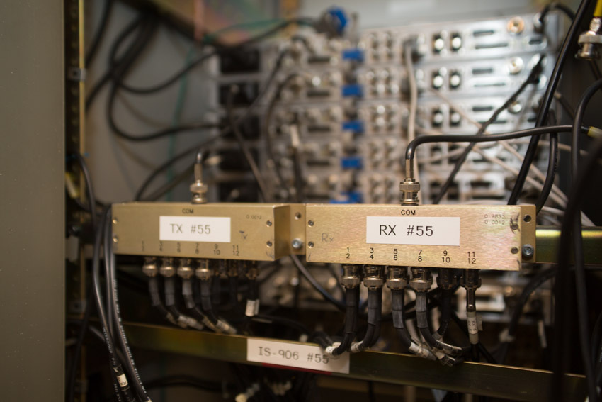
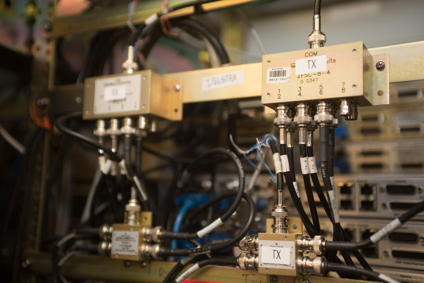
In the same rack, there are installed “group splitters” of the IF, which distribute signals between the racks with modems:
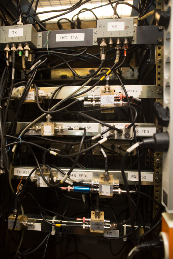
Each pair of splitters is a reception and transmission of one transponder.
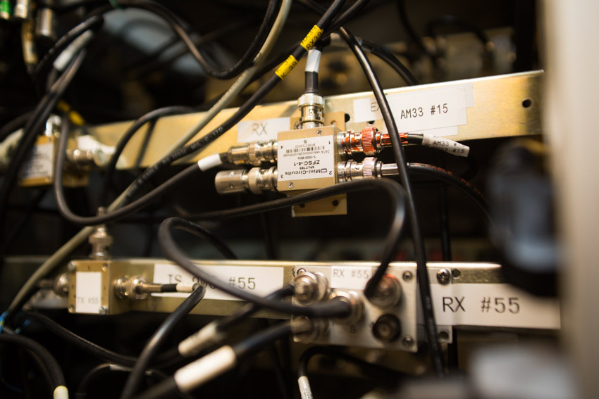
For “Rx # 55”: taps from the group splitter receiving to two racks and to the spectrum monitoring system (connector marked with a red marker).
A similar scheme is used for distributing signals to individual modems inside modem racks:
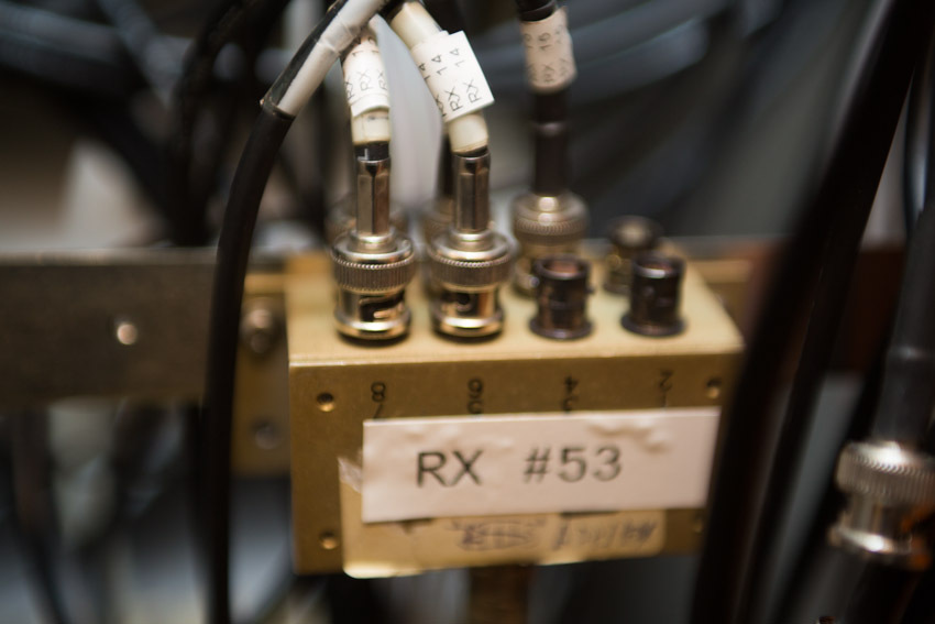
If modems operating in several trunks live in some rack, then the corresponding number of receive and transmit splitters is installed in such a rack:
This all works well for the IF 70/140. But for L-Band, the attenuation on the cables between the roof and the hardware becomes unacceptably high. And we use devices that allow us to shove an analog RF signal into optics:
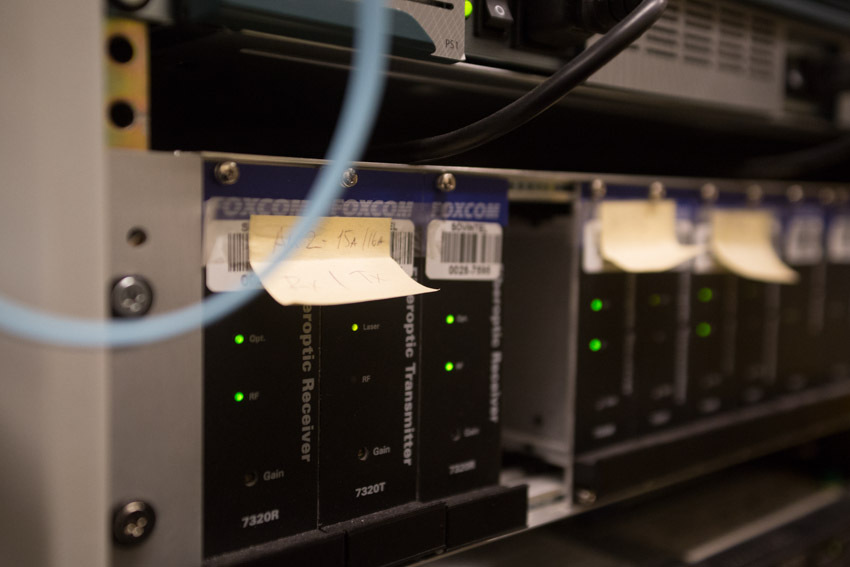
In addition to noticeably less attenuation, there is also a complete absence of radio interference and interference on the cables!
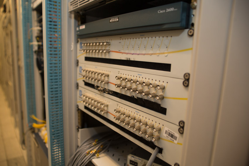
The parameters of all signals can be monitored by a spectrum analyzer. It is installed right there in the rack of the PCH wiring. To control for each of the trunks, special taps are provided, terminating in connectors on the front panel of this rack.

Okay, let's go to the modems ...

A modem is a device designed to interface a kind of digital interface with an analogue channel. Simply? For satellite modems - not really. The satellite channel is not a “relay” channel, to keep a decent energy here is an unaffordable luxury. And in order to work on such a noisy channel, the modems are equipped with very advanced codecs. The task of the codec is to add “redundant” check bits to the useful information at the coding stage. And at the stage of decoding - to recover the information sent by these check bits, removing errors from it. And you need to encode information with minimal additions, and decode - as correctly as possible and in the shortest time. Almost all the algorithms for which the decoders work are known for a long time. But if the implementation of a simple decoder by Witterby was available in the last quarter of the last century, then modern codecs (TPC, LDPC, VersaFec) could appear only after significant breakthroughs in computing that happened in the last decade. Modern codes that are used in satellite communications, just for some decibel parts, do not reach the theoretical Shannon limit in terms of performance.
Above - the very first modems that were able to work with 16QAM modulation. Below are their more modern, faster and more productive counterparts. At the same time they are noticeably smaller, easier and more economical.

These were modems capable of doing “fixed channels”. But the equipment for providing channels on demand:

It looks like the same cables and the same cards. But in reality, this is a more supercomputer and powerful router than a classic modem. After all, his task is not just to organize an error-free channel, but also to divide this channel among all sufferers. Considering the “classes of service” established for a specific user and for a specific type of traffic. And to do it, again, with a minimum delay for processing. And divide so that regardless of the number of allocated timeslots and the number of transmitted packets, the packets for each end user have the minimum jitter.
Channeling equipment is further away in the chain. A lot of things are placed in the same racks where modems are installed. This minimizes the length of the interface cables.

Satellite channels can come to different packet switches.
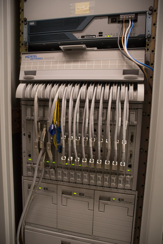

Well, “everyone knows about tsiski”. And this is the Nortel Passport. Old enough car. But, perhaps, it is better (more careful and gentle) of all copes with voice traffic.
Channels can go further, through optics:
And to switch from one network to another:
There are still quite a few fossil TDM-multiplexers Newbridge, rightly considered the best in its class. “A long time ago, in a galaxy far, far away ...”
See how we have fun under the raised floor. And this is not the most filled place. Over the years, the operation of cables arrived and the space below was rapidly consumed. Here, for example, you can raise the tile and calmly lower it back. But I know a couple of places where you lift a tile, and then you feel like a person stuffing toothpaste back into a tube.
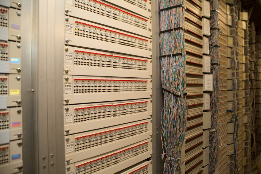
Almost the first crosses into the "outside world", which appeared in this hardware:
Cabinet downstairs - telephone "echos":
Copper crosses in front ...
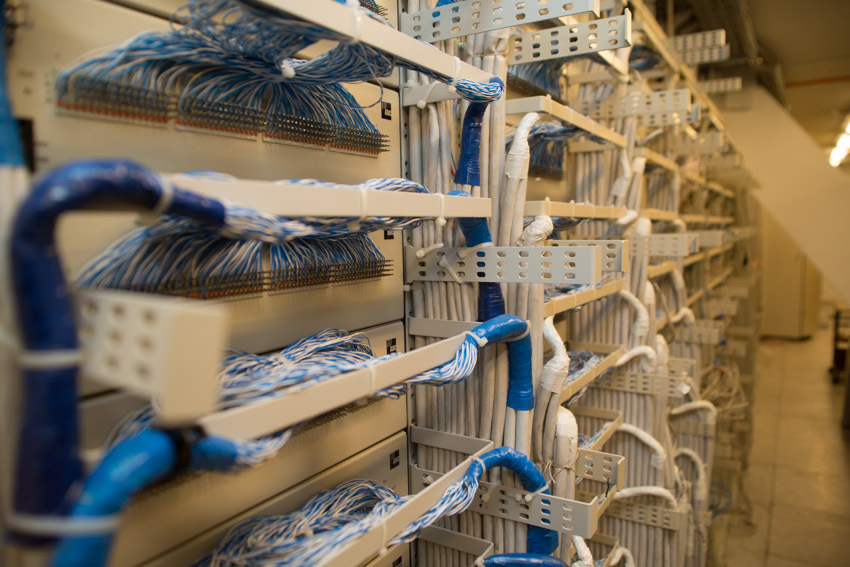
... and behind:
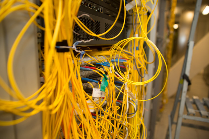
And still - optical:
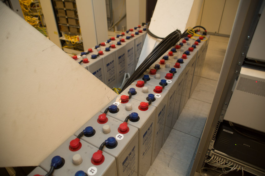
Low voltage batteries and their monitoring system:
Yes, all this splendor was already installed in the advanced hardware. When it all began, there was a small room. Then, right when the equipment was working, the walls neatly broke and the hall expanded. Well, are you ready for such an experiment today?
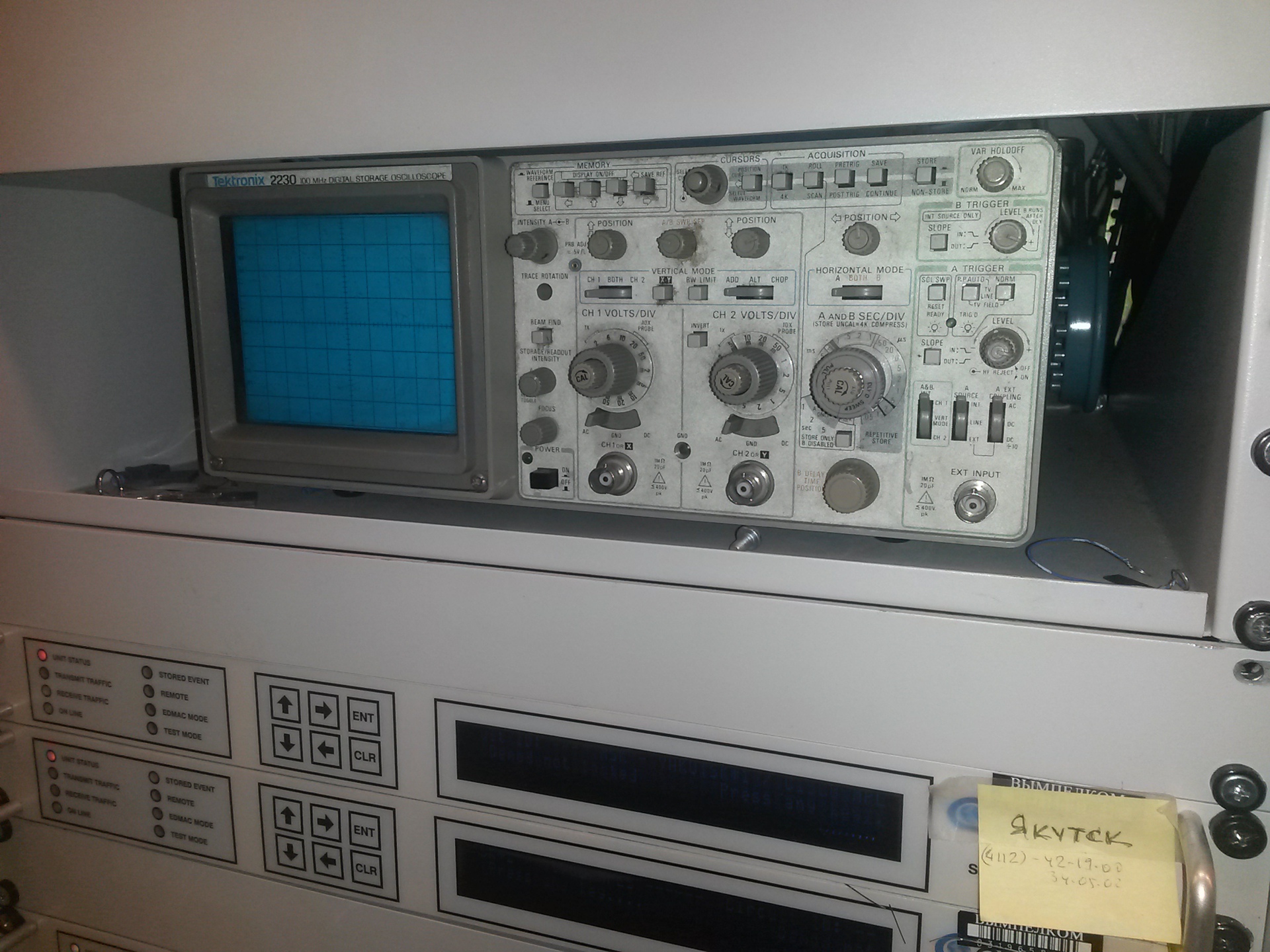
And this is a natural, good old oscilloscope, which continues to live in a rack with the first modems for 16QAM.

Old modems were made by engineers and for engineers. Yes, they had a built-in diagnostics that said that the modem was bad. But what exactly is bad - she did not say (and now she doesn’t really speak, to be honest).
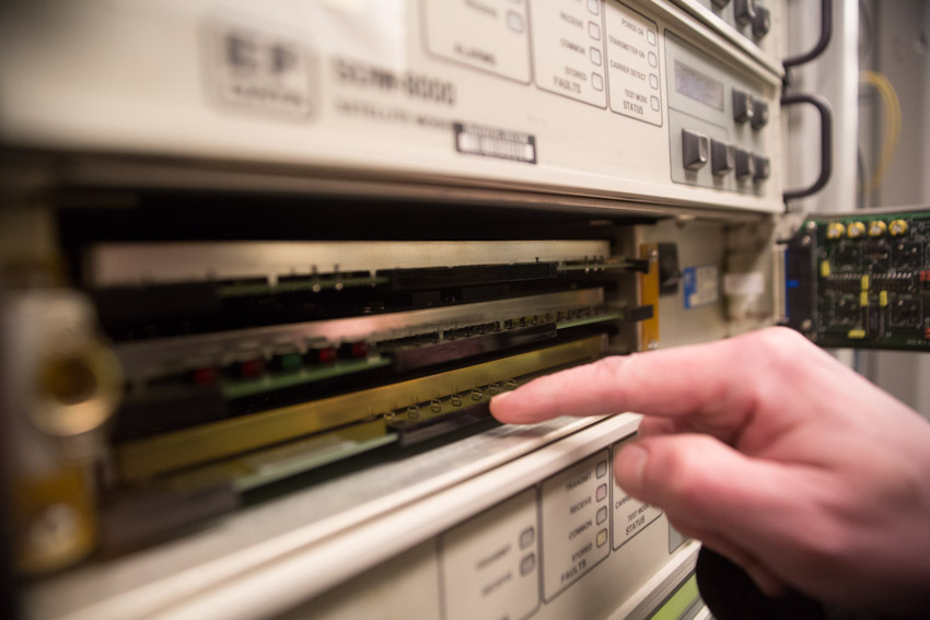
And what did the true engineer do? That's right: threw back the front panel of the modem ...
connected the oscilloscope to the control points I and Q (the key control points for the standard costas demodulator circuit) ...
and considered the type of eye diagram received by the modem:
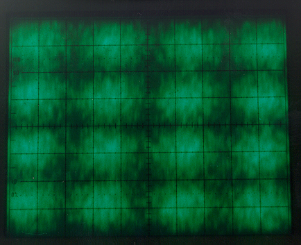
This is very good.
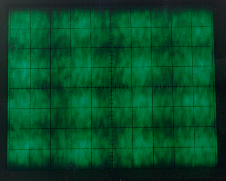
This is just good.
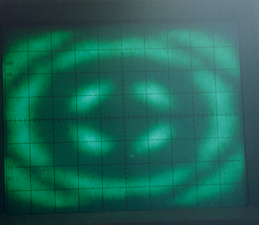
But this is very bad. Is everyone clear?
By the way, only in the latest versions of modems, the developers have returned to the ability to view eye diagrams. True, now it is implemented on a qualitatively new level. The oscilloscope is no longer needed, just a web interface.
And our ancient modems are used from time to time as a simple, convenient and reliable tool for measuring paths.
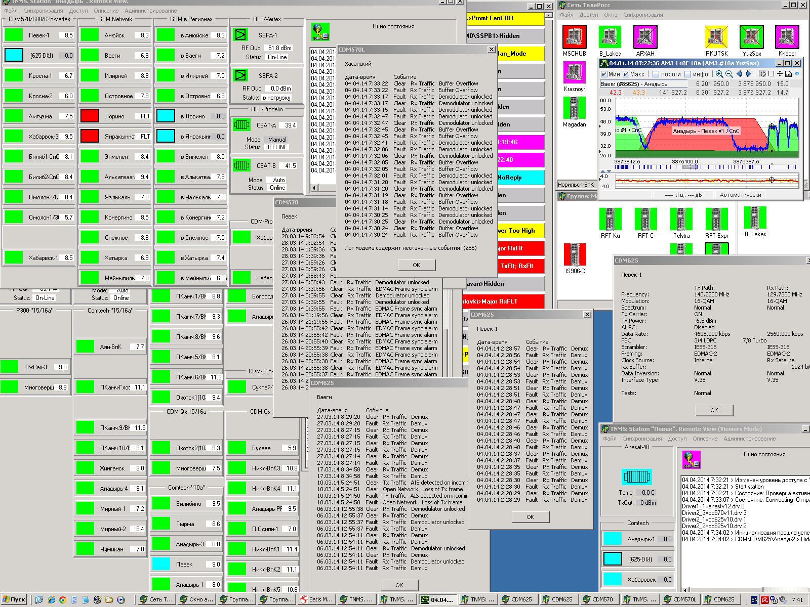
Normal operation of any network is impossible without monitoring systems. Our satellite network operating in 9 time zones and using satellites, some of which are not visible from Moscow, is no exception (the Earth is round; the Far East, on the other side).
: «» ( , ?), «» « » .
, , . , , , . , «» . , .
, . , , ( — ) .
, « » . , - , , , , … , — , .
, . - , . , , , , .
- . , , , , — — . , . : , , , .
, , . , . , - , - «» , .
, , — . , .
, «» . , , — ( , ) : 4 .
It all starts and ends with the antenna:
')
The antenna, besides, in fact, the mirror and the irradiating system, incorporates waveguide paths, LNA and (optionally) auto-tracking system, anti-icing, drying of the waveguide path. Caution traffic .
The radio equipment is located in the immediate vicinity of the antenna: transmitters (microwave power amplifiers), converters, active equipment redundancy systems, and auto-tracking and anti-icing controllers. Between the radio equipment on the roof and the modems in the equipment room are “IF signals” (intermediate frequency, low 70/140 MHz, or L-Band 1 GHz). The frequency converter is supplied via cables or with the use of special “frequency converter via optics” devices.
So let's go over what and how it works here in the form of a short FAQ.
- What kind of data is transmitted most often?
Since VimpelCom is better known as a cellular operator, it is not surprising that a significant part of the traffic is exactly the traffic of the mobile network. Nevertheless, a very substantial part of the traffic is “non-mobile” traffic: corporate networks, trunk voice, Internet. If we take not the ownership of the traffic, but its type, then we are not unique here: a significant part of the traffic is data, including the same Internet. As, however, and on any other modern communication network.
- How many satellites use the network?
We have one of the largest satellite networks in Russia, when viewed in terms of the overall speed of the channels. And for her work now used a dozen satellites, scattered in an arc from 57 to 183 degrees east longitude. For the inquisitive: 183 degrees east longitude - yes, in fact it is already 3 degrees west. But the satellite has a "service area" in the eastern hemisphere, and therefore it is listed behind this hemisphere.
- Why do you need such a large antenna mirror?
Actually, this is a topic for a separate article entitled “The Power of Satellite Lines”. But if it is short, then this: the larger the diameter of the mirror, the narrower the beam forms the antenna. And the more energy goes precisely into this beam, and does not fly apart in all directions. An ordinary pocket flashlight: the larger the reflector of a light bulb, the further such a flashlight will be beaten. It's all the same. Why is this necessary and why it is impossible to simply put the “light bulb” (i.e., the transmitter in our case) more powerful? Can. But at the same time you will improve energy only on the line "Earth - space". And the signal sent by the satellite back, you still have to manage to catch. And if on the receiving side you have a small antenna, then to get the required signal-to-noise ratio at the receiver input you will take more energy (resources if you want) from the satellite. And the onboard resource is the most expensive in the whole scheme. For illustration, a diagram from the legendary reference book Satellite Communications and Broadcasting, edited by (no less legendary) L. Ya. Kantor:
All that is up is the gain / gain of the signal; all that down is loss / attenuation. See bursts up near each of the antennas? This is precisely the gain in the power industry, which is the greater, the larger the diameter of the antenna. Attentive: the diagram shows only one span: "Earth - space" or "space - Earth" (optional). But for the second span - all the same. Antenna gain also depends on the frequency range in which it operates. And the higher the frequency, the greater the gain. Therefore, an antenna with a diameter of 3.5 m, operating in the Ku band (11/14 GHz), has approximately the same gain as the 7 m antenna operating in the C band (4/6 GHz). Now it is clear why the overwhelming majority of direct television systems use the Ku band in particular?
- What is the minimum size of the reflector? Why are there less cymbals on television?
- What you need to know about the ranges and polarization on the fingers?
The most common are two frequency bands: C (middle frequency up, on the Earth-to-space line around 6 GHz, down frequency - 4 GHz) and Ku (14 GHz up, 11 GHz down). The entire available band on the satellite is divided into transponders (or trunks), spaced apart by frequency. For simplicity, we can assume that the transponder is a set of a receiver, a frequency converter, which carries the signal from frequency up to frequency down, and a transmitter tuned to a specific frequency range. And there are several such transponders on the satellite (several dozen if we are talking about modern “heavy” satellites). To be able to use the same frequency twice the signal is divided by polarization. In C, circular (right and left) polarization is usually used, in Ku, linear (horizontal and vertical) polarization is used. As a result, the frequency-polarization distribution of transponders on a satellite looks like this:
Above - satellite reception of signals from the Earth, below - transmission to the Earth. The center frequencies of the transponders are indicated, and their conditional numbers. Inside each of the transponders are organized channels. Which and how much - depends on energy, the type of system used, the required channel band (s), and most importantly - the need for channels and the money available to the operator.
- Why is the uplink frequency always higher than the downlink frequency? And why are the frequencies different at all?
The higher the frequency, the harder it is to amplify. And the less efficiency has such an amplifier (in terms of output power, power consumption, weight and size characteristics). It is clear that with equal power output to the satellite you will put the amplifier, which is smaller in weight, consumes less energy and produces less heat. And it will be an amplifier operating at a lower frequency. And the frequencies are different because in a small volume (and very closely within the satellite) it is impossible to provide a large gain factor at one frequency. Attempting to do this will lead to self-excitation of the amplifier. Using different frequencies for receiving and transmitting, we divide the entire amplifier path of the satellite in half. And for each of the halves, the problem becomes quite solvable.
- What is the voice path from the satellite subscriber to the subscriber in France? Which nodes pass the data?
From the phone to the base station, from the base station to the satellite communications station, then to the satellite, from it to the central station, which is paired with this (Khabarovsk, Krasnoyarsk, Moscow ...). Further the channel with a call comes to the zonal switch. And if the BS is Ural, and the channel lands in Moscow, then it will have to go back to the Urals - this is what the GSM / 3G network operation protocol requires. The switch unpacks the data, extracts the call from them. And then - the same as in a standard PBX: by the number you can see where to send this call further (in this example - to France). Again in the highway to Moscow, in Moscow - in the "intercity", to the switch in France, there - to the called subscriber.
What is most funny, the Internet in GSM / 3G goes on the same principle. Irrational? Yes, but these are the requirements of the standards and architecture of GSM / 3G networks: dura lex sed lex. And dual use of the land highway is not the saddest thing. It is much sadder when a satellite BS connects to its switch, which, in turn, also has an uplink via satellite. And such a situation arises in almost all major cities that do not have access to the outside world through land channels (already mentioned Anadyr, Magadan, Kamchatka). In this case, the call (or data) of the subscriber goes through "two jumps". And this is not only double the cost, but double delays. But this is life, and everything can be used to - even to a conversation with a delay of 1.5 seconds. I note that in LTE networks, data transfer is organized more efficiently.
- How to determine where to “land” the signal if the satellite is visible from Khabarovsk and Irkutsk?
If the source of traffic (or, on the contrary, its final consumer) is located, for example, in Moscow, then, naturally, it is better to choose Irkutsk, having played for this about 50 ms delay. Due to the fact that we have a large network, many possible landing points, our own land lines and many satellites - for each case, you can choose the best option. Not so long ago, Intelsat presented its innovative scheme for the landing of user channels - Intelsat One . And we have been doing this for at least ten years, and without much noise.
For now. The next part is not so romantic - we go down to the control room and see why an engineer in the twenty-first century needs an oscilloscope, and at the same time we will carefully examine the signal path further.
Equipment
We descend from a cold high roof into a warm cozy hardware room . It is located in a fairly large room, where not only “purely satellite” equipment is installed, but also a lot more: channel and channel-forming equipment, PBX, optical and copper crosses, low-voltage power systems and their batteries. And, of course, air-conditioning and air conditioning systems. And this is not the only hardware located in this building.
At the entrance, as required by the rules of good tone, you need to pass the wave and wipe the feet. To speed up the latter, a special sticky pad was made, which carefully takes away all the dirt remaining after the mat:
IF cables from containers come in a separate rack. Here they are, find out?
In the same rack, there are installed “group splitters” of the IF, which distribute signals between the racks with modems:
Each pair of splitters is a reception and transmission of one transponder.
For “Rx # 55”: taps from the group splitter receiving to two racks and to the spectrum monitoring system (connector marked with a red marker).
A similar scheme is used for distributing signals to individual modems inside modem racks:
If modems operating in several trunks live in some rack, then the corresponding number of receive and transmit splitters is installed in such a rack:
This all works well for the IF 70/140. But for L-Band, the attenuation on the cables between the roof and the hardware becomes unacceptably high. And we use devices that allow us to shove an analog RF signal into optics:
In addition to noticeably less attenuation, there is also a complete absence of radio interference and interference on the cables!
The parameters of all signals can be monitored by a spectrum analyzer. It is installed right there in the rack of the PCH wiring. To control for each of the trunks, special taps are provided, terminating in connectors on the front panel of this rack.
Okay, let's go to the modems ...
A modem is a device designed to interface a kind of digital interface with an analogue channel. Simply? For satellite modems - not really. The satellite channel is not a “relay” channel, to keep a decent energy here is an unaffordable luxury. And in order to work on such a noisy channel, the modems are equipped with very advanced codecs. The task of the codec is to add “redundant” check bits to the useful information at the coding stage. And at the stage of decoding - to recover the information sent by these check bits, removing errors from it. And you need to encode information with minimal additions, and decode - as correctly as possible and in the shortest time. Almost all the algorithms for which the decoders work are known for a long time. But if the implementation of a simple decoder by Witterby was available in the last quarter of the last century, then modern codecs (TPC, LDPC, VersaFec) could appear only after significant breakthroughs in computing that happened in the last decade. Modern codes that are used in satellite communications, just for some decibel parts, do not reach the theoretical Shannon limit in terms of performance.
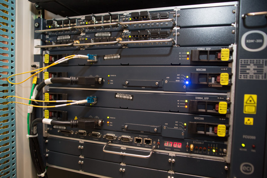
Above - the very first modems that were able to work with 16QAM modulation. Below are their more modern, faster and more productive counterparts. At the same time they are noticeably smaller, easier and more economical.
These were modems capable of doing “fixed channels”. But the equipment for providing channels on demand:
It looks like the same cables and the same cards. But in reality, this is a more supercomputer and powerful router than a classic modem. After all, his task is not just to organize an error-free channel, but also to divide this channel among all sufferers. Considering the “classes of service” established for a specific user and for a specific type of traffic. And to do it, again, with a minimum delay for processing. And divide so that regardless of the number of allocated timeslots and the number of transmitted packets, the packets for each end user have the minimum jitter.
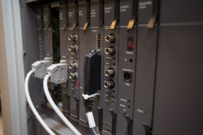
Channeling equipment is further away in the chain. A lot of things are placed in the same racks where modems are installed. This minimizes the length of the interface cables.
Satellite channels can come to different packet switches.
Well, “everyone knows about tsiski”. And this is the Nortel Passport. Old enough car. But, perhaps, it is better (more careful and gentle) of all copes with voice traffic.
Channels can go further, through optics:
And to switch from one network to another:
There are still quite a few fossil TDM-multiplexers Newbridge, rightly considered the best in its class. “A long time ago, in a galaxy far, far away ...”
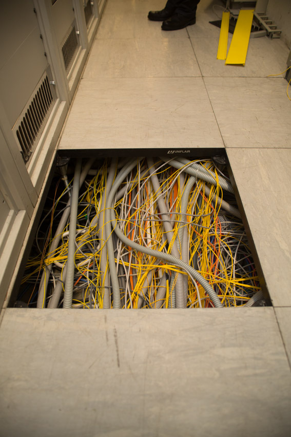
What else is there from the interesting? Well….
See how we have fun under the raised floor. And this is not the most filled place. Over the years, the operation of cables arrived and the space below was rapidly consumed. Here, for example, you can raise the tile and calmly lower it back. But I know a couple of places where you lift a tile, and then you feel like a person stuffing toothpaste back into a tube.
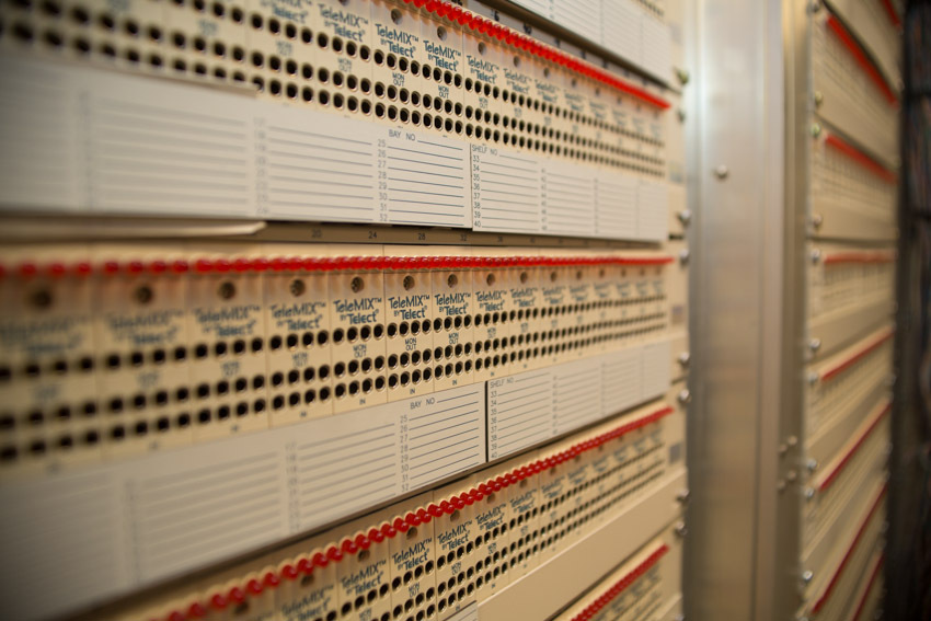
Almost the first crosses into the "outside world", which appeared in this hardware:
Cabinet downstairs - telephone "echos":
Copper crosses in front ...
... and behind:
And still - optical:
Low voltage batteries and their monitoring system:
Yes, all this splendor was already installed in the advanced hardware. When it all began, there was a small room. Then, right when the equipment was working, the walls neatly broke and the hall expanded. Well, are you ready for such an experiment today?
And this is a natural, good old oscilloscope, which continues to live in a rack with the first modems for 16QAM.
Old modems were made by engineers and for engineers. Yes, they had a built-in diagnostics that said that the modem was bad. But what exactly is bad - she did not say (and now she doesn’t really speak, to be honest).
And what did the true engineer do? That's right: threw back the front panel of the modem ...
connected the oscilloscope to the control points I and Q (the key control points for the standard costas demodulator circuit) ...
and considered the type of eye diagram received by the modem:
This is very good.
This is just good.
But this is very bad. Is everyone clear?
By the way, only in the latest versions of modems, the developers have returned to the ability to view eye diagrams. True, now it is implemented on a qualitatively new level. The oscilloscope is no longer needed, just a web interface.
And our ancient modems are used from time to time as a simple, convenient and reliable tool for measuring paths.
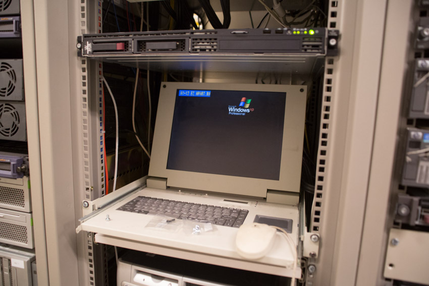
Network Monitoring and Operation
Normal operation of any network is impossible without monitoring systems. Our satellite network operating in 9 time zones and using satellites, some of which are not visible from Moscow, is no exception (the Earth is round; the Far East, on the other side).
: «» ( , ?), «» « » .
, , . , , , . , «» . , .
, . , , ( — ) .
, « » . , - , , , , … , — , .
, . - , . , , , , .
- . , , , , — — . , . : , , , .
, , . , . , - , - «» , .
, , — . , .
, «» . , , — ( , ) : 4 .
Source: https://habr.com/ru/post/255339/
All Articles