We are switching from STM32 to the Russian K1986BE92QI microcontroller. Setting up the project in keil and flashing LED
Introduction
In the last article, I shared my personal impressions of the recruitment I received and programmed the controller with a demo project using MT-LINK (it was also provided). Now that we have reviewed the entire kit in detail, it is time to start mastering it.
For the impatient - the result.
Create an empty project in Keil 5 for K1986BE92QI.
First you need to create a clean project. Of course, you can use the demo project as a basis, but the project with the number “2” did not start, and in the project “3” for some reason in the controller selection menu a blank sheet. It somehow alerted me. Project with the number "1" is not in principle.
- 1. Go to Project -> New uVision Project ...

') - 2. Create a folder for the project (there should not be Russian letters on the way), write the name (also in English) and save.
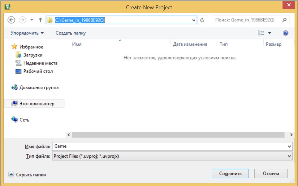
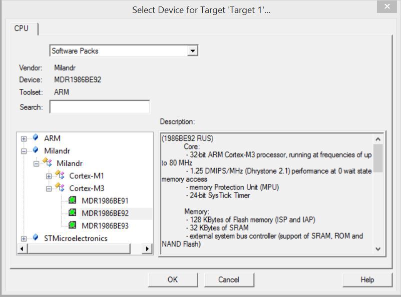
- 3. Choose our controller.
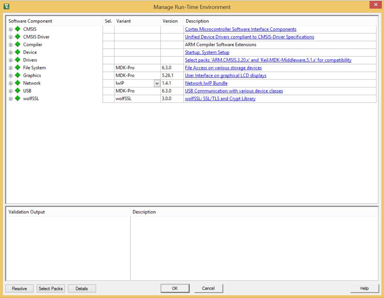
- 4. In the window that appears, just click "OK". Honestly, I never managed to set up a project through this editor so that everything compiles from the 1st time. Always had to change something. Most often it turned out that it was easier to do it yourself.
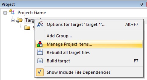
- 5. A project tree has appeared in the upper left corner. Now we need to create the necessary subcategories. To do this, click on the uppermost folder with the right mouse button and select “Manage Project items ...”
- 6. In this menu, 2 times click the left mouse button on the folder whose name we want to change and write what we want. Again, better in English. To add a new folder serves as an icon to the left of the "red cross".
We will need at least 4 folders:- 1. Under user data (our files).
- 2. Under the LCD driver (those included).
- 3. For code to work with Flash.
- 4. Under SMSIS and the like SPL.

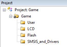
- 7. After renamed all the folders, click "OK". The catalog should have a rough look.
- 8. Next we need to get all these files. We will take them from the working demonstration project. By the way. Just now I noticed that the project was written under keil 2. This struck me a bit. Another interesting fact was that between the demonstration project "2" and "3", judging by the information of the last change - 3 months passed. And our project is closer to our time. From it we will take the files (where to get this demo project - said in a previous review article). Copy need selected files. Moreover, main.c (as well as any of your files) is best removed in a separate folder. I created the User folder for this and put main.c there (we will change it and we will base it).

- 9. Next we need to add the library files to the project. Adding occurs as follows. Right-click on the desired folder in the project tree and select "Add Existing Files to Group 'Group Name' ...".

In the window that opens, select the file type “All files (*. *)”. Then select 1 or select multiple files.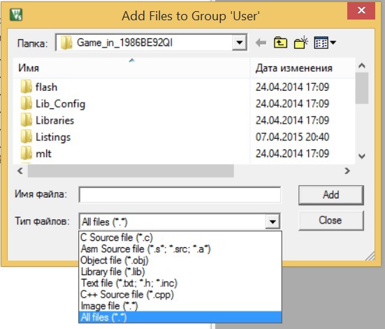
Add need:- 1. In the folder User -> "User -> main.c". This is our main file. Having slightly changed it, we will start writing our code in it.
- 2. In the folder Flash -> "flash -> MilFlash.c". The library for working with the Flash controller is stored here.
- 3. In the folder LCD -> "mlt -> mlt_lcd.c". Library work with LCD, which is installed on the board.
- 4. In the folder SMSIS_and_Drivers -> "Libraries \ 1986BE9x_StdPeriph_Driver \ src -> all .c files". Here is stored analogue SPL at STM32. Simply put, these are “wrappers” that allow you to control its peripherals (conclusions, uart, etc.) without going into the structure of the controller.
- 5. To the SMSIS_and_Drivers folder -> "Libraries \ CMSIS \ CM3 \ DeviceSupport \ 1986BE9x \ startup \ arm -> startup_1986be9x.s". This is a startup file. All "transition vectors" are spelled out here. In other words, on any interruption (for example, pressing a button), the controller returns to this table and looks where to go to execute the code further.
- 6. To the SMSIS_and_Drivers folder -> "Libraries \ CMSIS \ CM3 \ DeviceSupport \ 1986BE9x \ startup \ arm -> system_1986BE9x.c".
The result should be such a tree.
- 10. Next, we need to clean the main.c. file a little. To do this, click on it by clicking the left mouse in the directory tree. Remove everything except the shell functions main and #include files. Should stay like that.

- 11. As you can see, there is a cross near the topmost #include file. Keil simply does not see this file. In order to fix this, we must tell him where to get this file. To do this, press Alt + F7. In the window that opens, go to the tab C / C ++. A little distraction. In the future, I will often use techniques that keil will not understand by default. In order to fix this, you need to press the check mark next to the inscription «C99 Mode». This will give the opportunity to write on a more advanced standard of the C language than it was possible to do initially. Next, click on the rectangle with "..." inside. Right near the line with the signature "Include Paths".

- 12. In the window that opens, click on the icon with a rectangle to the left of the cross. This will create an empty string. In the right corner of the created line click on the "...". Then we specify the desired folder in which the files of interest are located. After that, click "OK". Folder will be added. It is necessary to add all these paths. If you notice, all links except one are relative. That is, they come from the root directory. But 1 comes from "C: \". This is a link to the directory with the project. It should also be specified.

Click "OK" and go to the file main.c.
Compile the simplest program.
Insert into the main function an infinite loop with the counter increment by 1. Now our file should look like this.

Do not forget that at the end of each file should be an empty line. Keil regards this as a warning that often gets on your nerves. Of course, it will compile, but the fact of the warning itself is alarming.
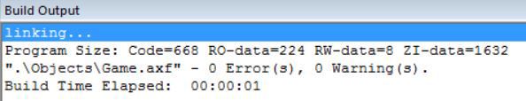
At this setting is over. We can recompile our project by pressing F7. If everything went well, we will see it.

Now it remains only to configure J-LINK in the settings and you can upload. How to configure it - was described in detail in the previous article.
By the way. J-LINK sees the chip without connecting additional power, as well as allows you to debug the chip. So external power is not particularly necessary. When navigating through the lines of the code, you can see how the screen tint flashes.
We adjust a controller leg for work with a LED
Having run through the table of contents of the documentation, I did not see anything about the timing of the periphery, so I immediately set about adjusting it. Remembering all the horrors of SPL in terms of setting up I / O ports in the STM32, the thought of using the bundled libraries disappeared immediately. And it’s not good, just like that, without having time to play with registers, hide behind libraries, in which, by the way, mistakes are not excluded.
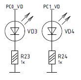
First, let's understand which port we need to configure. In the "Debug Board 1986EV92U, K1986BE92QI (MDR32F9Q2I) \ Printed circuit board 1986EvBrd_LQFP64" there is a file 1986EvBrd_64_Rev2.pdf, which shows the circuit board. On it, we can see that 2 LEDs are connected to PC0 and PC1 pins. Fine. Do not have to suffer with displacement.
I liked very much that Milandra had all the information about the chip line in one document. The STM32 is very confused with the documents ... Let's look at the I / O port diagram. Something vaguely resembles the port scheme of the STM32. Not seeing anything that would have caught the eye, we are going to tune the registers.

Since I did not know exactly how Milander called his ports, I reached into the ports configuration library. I saw the following there.

Well, a little higher.

After making sure that the address of port C coincides with the address in the data sheet, I created a new function in the main.c file (The main function is surely higher! Otherwise, the function prototypes in the .h file will have to be described. And these are unnecessary troubles for now.).
I start writing PORTC-> (by habit), hold down ctrl + space and see the following.
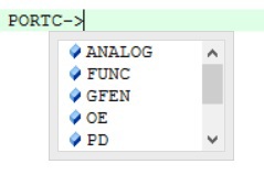
This is a familiar picture. Very happy. Then I began to look at which registers needed to be changed.

We need an LED on the port "0", so we can write: PORTC-> RXTX | = 1;
With this we translate the 0th bit of the port to 1. Thus, lighting the diode on port 0. But before turning it on, it is worth setting it up ...
So this action is performed last and before.
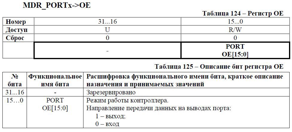
We have a way out, so: PORTC-> OE | = 1;

We leave unchanged, since the default is zero everywhere.
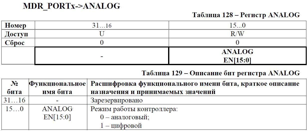
And here we need digital: PORTC-> ANALOG | = 1;
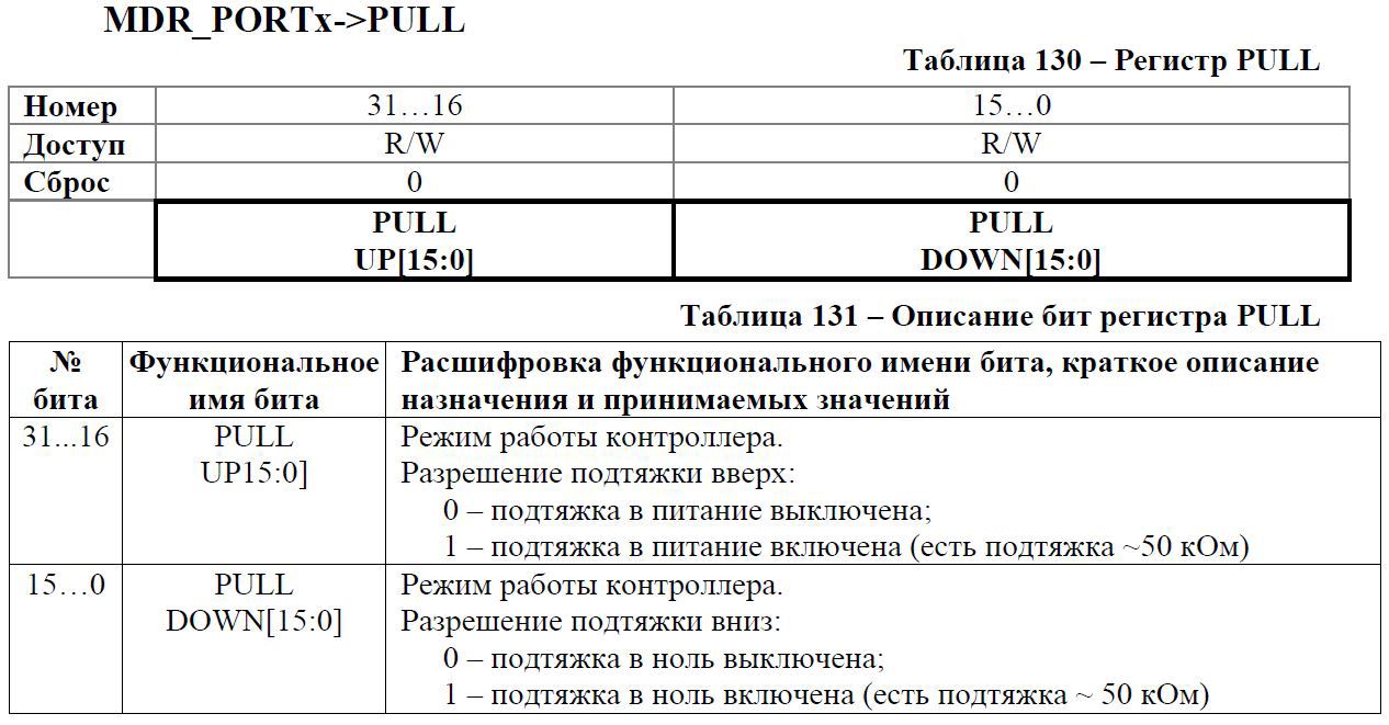
We do not need a brace, so skip it.

Well, we don’t need that either ...
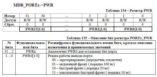
And here we need to choose the speed. The default is everything. Choosing a slow front. For the LED it is quite enough: PORTC-> PWR | = 1;
Well, the last register. Generally unknown to me earlier thing. This has yet to be resolved.
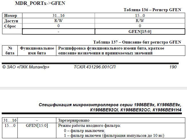
Well, with the setting we finished. BUT, if we now sew up this code, then nothing will work. For a long time I tried to understand what the problem was, yet once again I did not carefully read about the clocking system. There is not a word about clocking in the ports section. But there is a separate chapter in which it is written how and what needs to be clocked. I went there and saw the following.

We need ports. This fits well with the description "peripheral blocks". We are looking for this register and here.
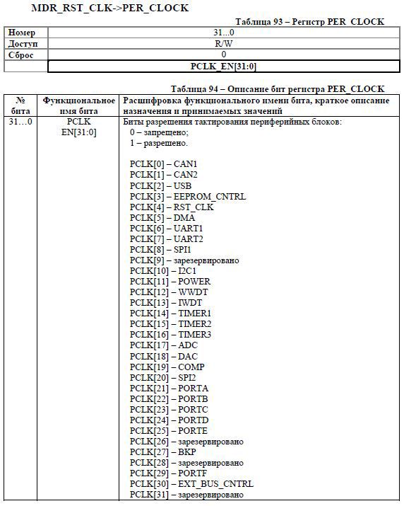
It remained only to understand how keil is called this register. Since I did not find anything in the libraries, I went with a selection. As a result, it turned out that it is called RST_CLK. Well, then we only need to write "1" in the desired block.
RST_CLK-> PER_CLOCK | = (1 << 23);
On the "PER_CLOCK" came out by chance. When I wrote “RST_CLK” I pressed ctrl + space and after the list appeared, “p”. After choosing the appropriate option.
The result is such a code.

The code compiles and we get.
Russian comments in keil 5
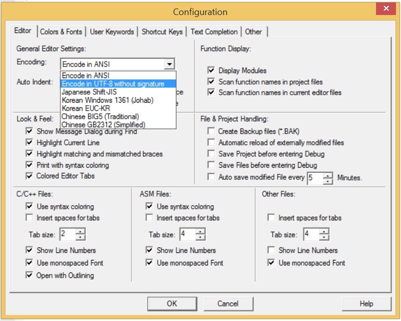
Now it is worthwhile to place comments on the code, but this is not possible in Russian. There are incomprehensible characters, in order to be able to write Russian comments, you need to go to Edit -> Configuration.

And there change the encoding, as shown in the figure. Then click "OK".
Blink LED
Now we will write a code that will flash using the LED.
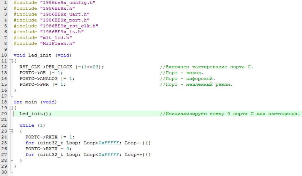
We sew and rejoice! The speed is taken from the LED flashing experience on the STM32. The LED flashes at a rate of approximately once per second.
Everything. It seems to have missed nothing. I advise you to archive this project immediately. Then to use as a blank.
The project is attached to the article .
Once again I remind you. In the project settings there is one link to the project directory relative to “C: \”. So the project will work only in the same way as in the article. You can easily change the way and use it freely.
Thank you sguwenka for fixes.
Source: https://habr.com/ru/post/255323/
All Articles