We turn from STM32F103 to K1986BE92QI. Or the first acquaintance with the Russian microcontroller
Introduction
On the eve of the new year, I, like many Russians, actively followed the state of foreign currency. But not simply because of his own interest, but because at that time he was finishing his device, which was required to be shown at a school and district conference. Since the name of the work was such a word as “budget”, we had to indicate in the presentation the cost of each component, up to the resistors and jumpers. Initially, when the dollar was worth about 30 rubles, the device really was a budget. Both at house assembly, and at conveyor. But when the price of a dollar exceeded 100 rubles, I decided that I needed to look for an alternative to foreign components.
At this point, for several months already, I studied the work of the STM32F100 and STM32F103 microcontrollers, applying them in practice in the presentation device. From such giants as STM32F429, I had to refuse. Since the cost of 1,800 rubles per case is transcendental for a “budget” device, the functionality of which has only just begun to exceed the capabilities of AVR Atmega32.
Selection
The task was clear. It was necessary to find a Russian analogue of the STM32, not inferior to him in features. And then I remembered that about a year ago on Radio Kote I opened a branch in which I asked for help with the choice of a Russian-made microcontroller. Then I was able to learn about the company Milander and its line of microcontrollers. Asking for the price list, I was amazed at the prices. All of them were around 10-30 thousand rubles per case. Depending on the model and military acceptance. But among all the microcontroller stood out, worth 400 rubles in a plastic case (K1986BE92QI). At that time, I decided that it was too expensive. But in this situation it became as acceptable as the purchase of the corresponding STM32, and I just wanted to look at the Russian microcontroller. I looked at its characteristics, I was very happy. The controller fit my needs
.

Expectation
Without hesitation, I wrote to tech support, from where I was sent to the customer service department. After some conversation in which I described why I needed this kit, the company representative kindly agreed to provide me with a free debugging complex, a programmer and a separate microcontroller case.
')
This conversation was at the end of December. Then the representative notified me that the controllers in the plastic case are not available. We'll have to wait until the beginning of February. I said that I was ready to wait and began safely building up the project code so far under the STM32, putting more emphasis on the logic of the device. Since the hardware will still have to be completely rewritten for the new MK. Time passed, but there was no answer. And closer to the end of February, I decided to write. The answer was that so far the controllers in plastic are still out of stock. And at the end of March, when it was already necessary to demonstrate the device, I wrote to the representative to find out how my set was. To which he received an unexpected response - "Appeared in stock, specify the address." They sent it by urgent mail (as an interesting fact - not by the Russian post, but by the partner post) and after 2 days it was already in my city. I refused the courier delivery and went to pick up the set myself. And in vain ... I had to go far and in a very unusual place. Upon receipt, they asked me for a passport and a painting, after which they safely delivered the box with the goods. Since before the trip to Moscow, for the sake of which a set was originally needed, there remained a few hours, it was not possible to enjoy the set, but I had time to consider it.
Study of
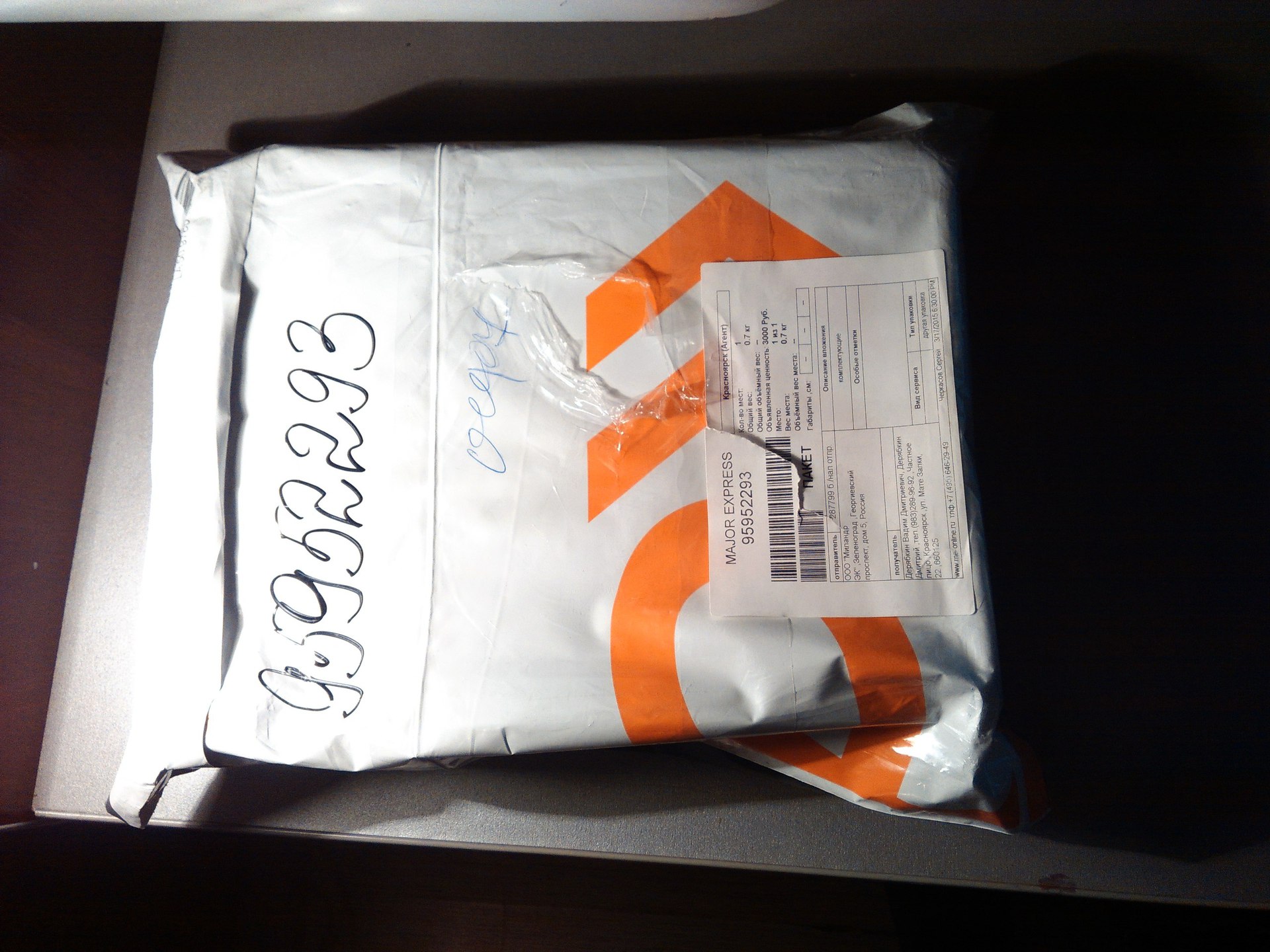
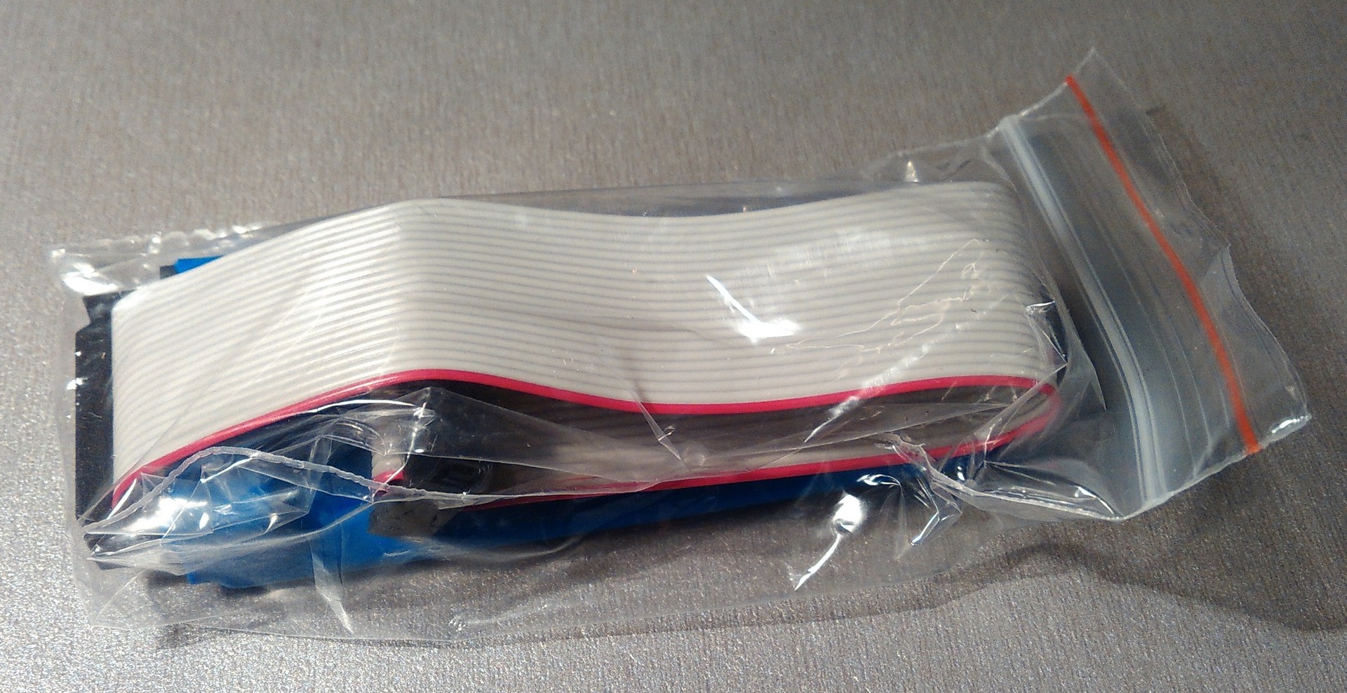
In stock, I took this bag:
Having unpacked that, I saw this box, on which lay the invoice with the list of issued:

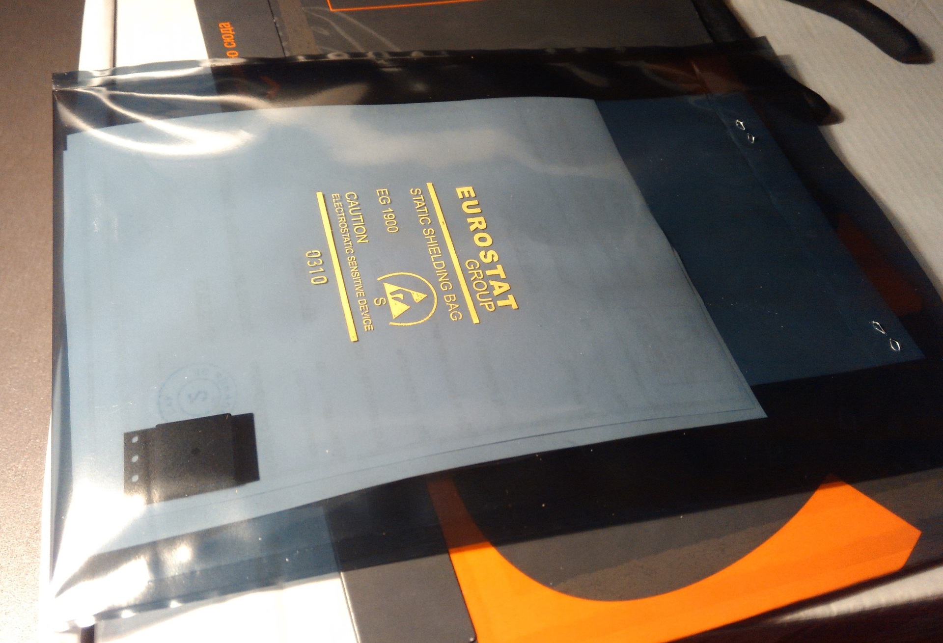
Under the invoice there was such an envelope with an advertisement for the courier company:

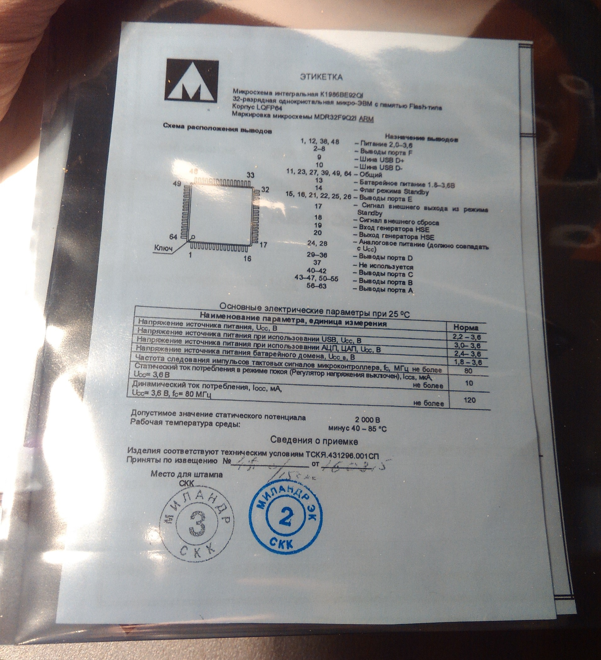
In which lay this miracle. Yes, yes ... A whole sea of paperwork to one body ...
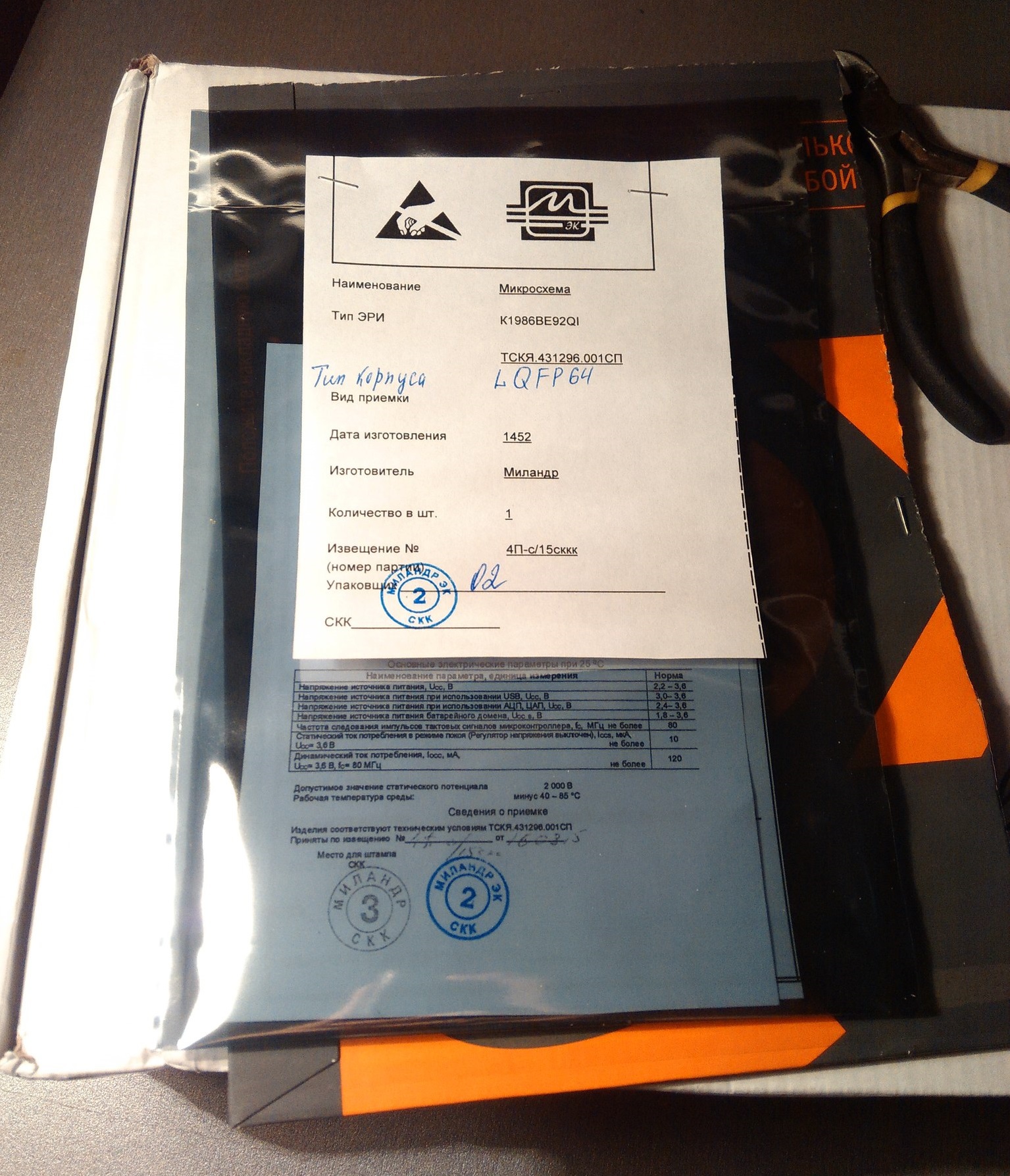
Separately, I was pleased with the description of the legs and the main parameters of the microcontroller. Maybe it’s accepted everywhere, but for me it was new.
Well, under all these papers lay the controller itself:
Putting the envelope with its contents aside, I began to open the box. And here it is, the long-awaited moment ... Oh, no. Another brand disk. What is on it - I will tell later.

Remove the foam and here it is. Long-awaited set:
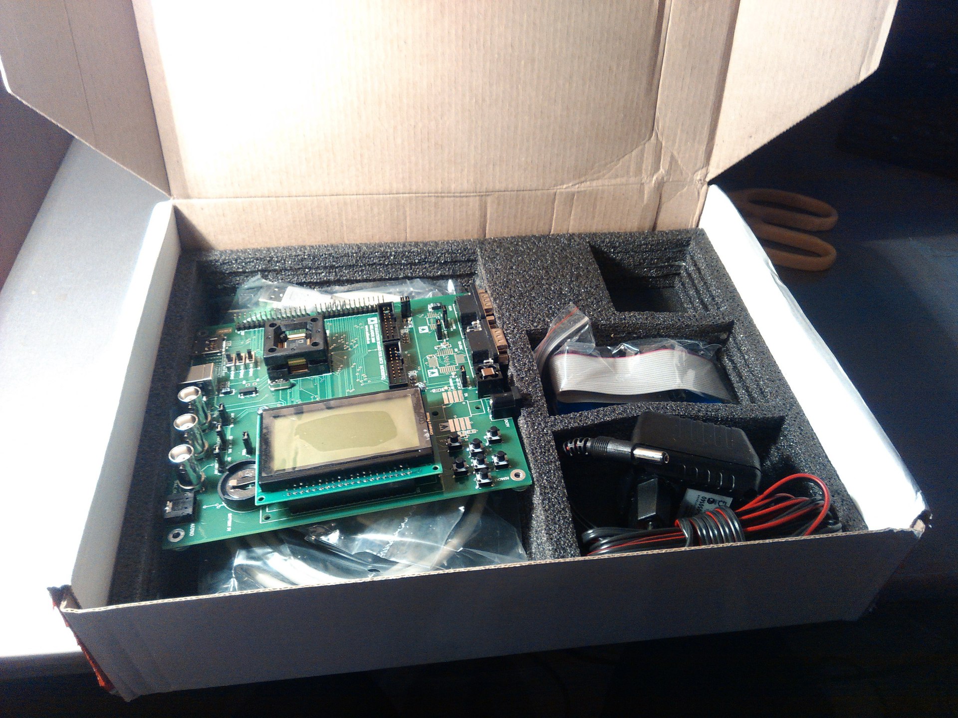
Debug board
Consider everything in detail. Let's start with the main thing. Debug board Immediately striking are the huge cable exits on the left side of the board, as well as the massive “bed” for the microcontroller. The presence of a microSD card is also pleased. Surprised 2 JTAG port. For what - I do not understand. The first time I see this. Also pleased with the presence of a minimum set of keys. After STM Discovery, where there was one user button - this is an incomparable plus. The socket for the battery is very massive. And in general, the whole board seems very reliable. At least due to the fact that the thickness of the PCB is seemingly more than two millimeters. Just can not help but notice the absence of several chips, for which the layout was made. Apparently, the board was made taking into account the fact that different cases of the same chip may be available (on the bottom of the board, in the same places, there are chips). Also on the board there is a Jack connector with a microcircuit-amplifier. This is exactly what I need, so I am really happy about it. The upper side, as you can see, is made without the use of polygons. I just don't understand why. My guess is to reduce noise.

Here are the big sockets for wires:

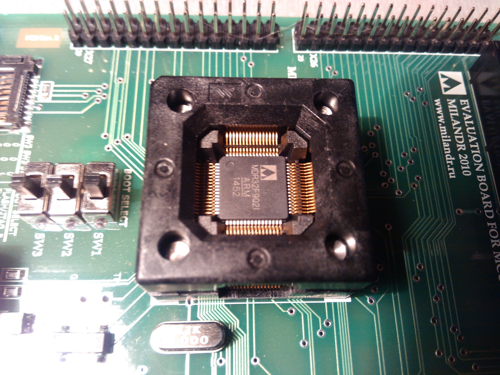
And here is the fact that I was very impressed. Cot under the SMD chip. Never seen anything like it before. And in general was very impressed by the fact that such exist. I have never seen anything like this on any debug board before. I would know that such exist, would solder into each prototype. Since it often happens to burn the controller's legs when the modes are not programmed correctly. And with frequent soldering, the STM32, like other controllers, eventually dies.
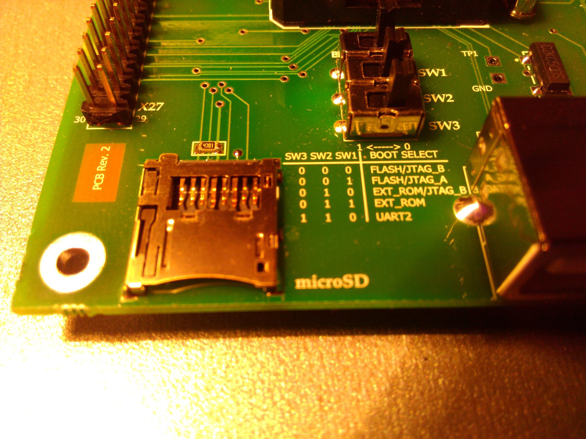
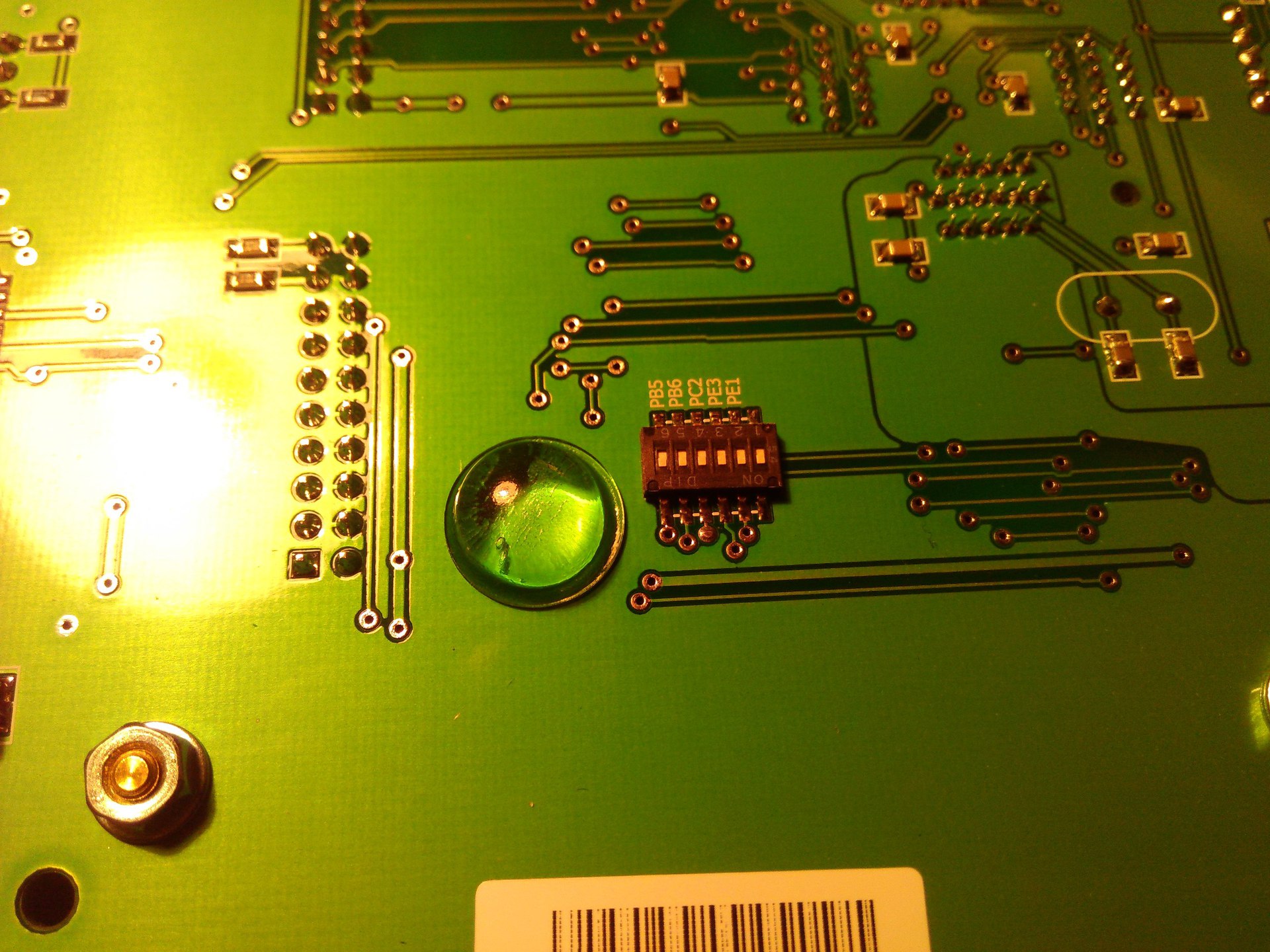
On the board there are also mode switches with signatures. This pleased me and allowed me to start learning without studying Datasheet.
There are also 2 COM ports on the board. I need them unnecessarily, since there is no COM port on the laptop. But the external power is very useful. And the question of external nutrition has already come, then here it must be chosen with the help of a jumper. Either from USB or from an external source.

Now we can look at the bottom side of the board:
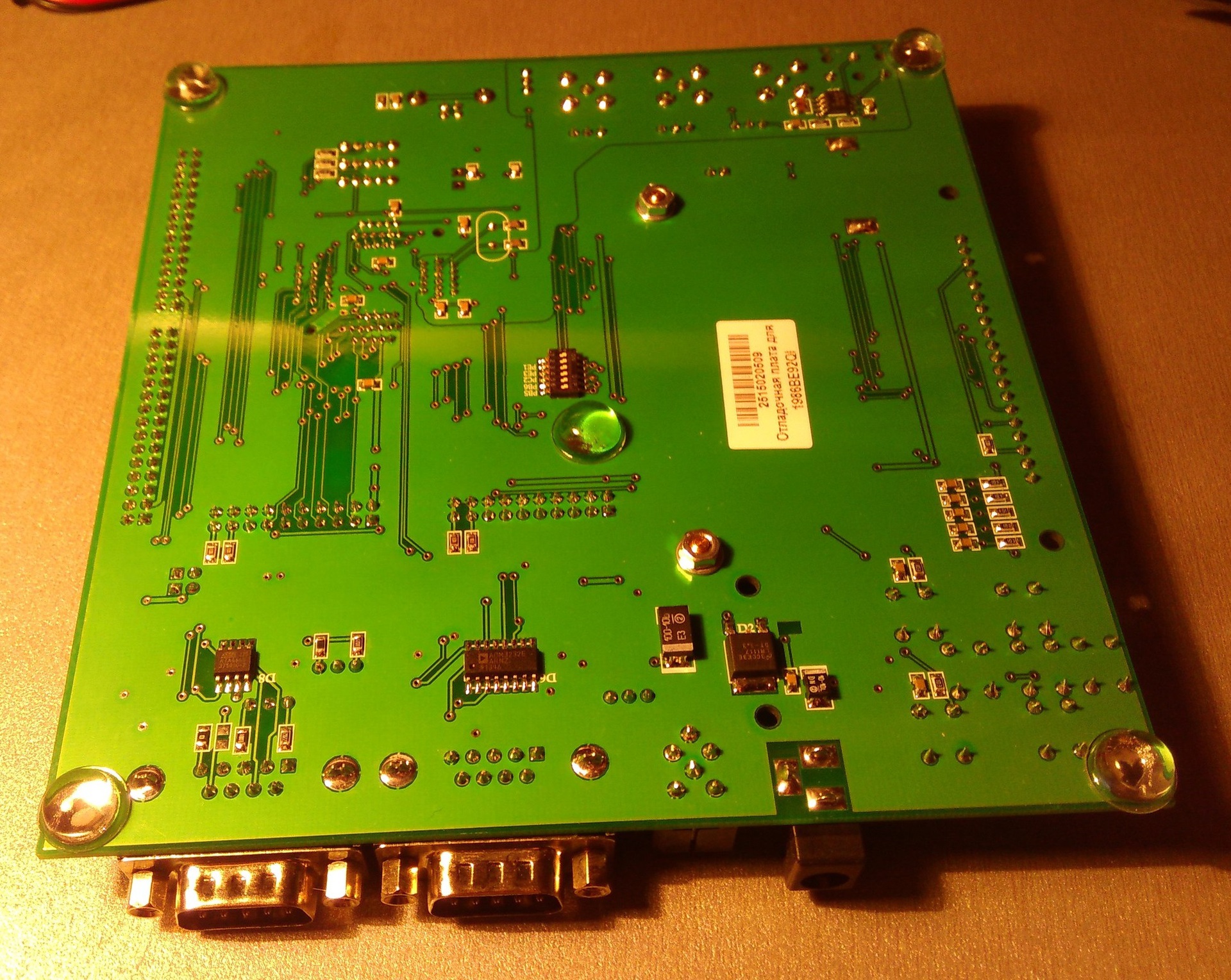
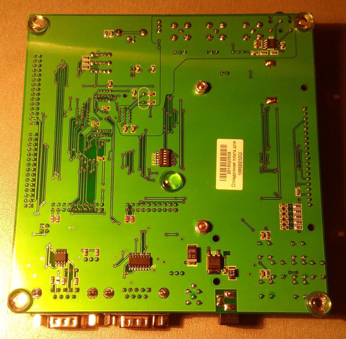
Here we already see the presence of polygons. As well as interface chips and amplifier. Well, every crumbling. The only thing that caught my attention was a set of switches. This is exactly what was missing in STM Discovery. Here I can turn off all the excess peripherals, if it is unnecessary for me and use the legs of the MK in its own way. And in STM Discovery, it was not rare that different peripherals intercepted data and sent responses, causing the communication channel to become unusable.
I also liked the Stoics on the board. If the board wants to be used in the final device - they can be removed and bolted through the holes under them, fasten it in the right place.
On this with an overview of the board, I think that's enough.
The remaining items
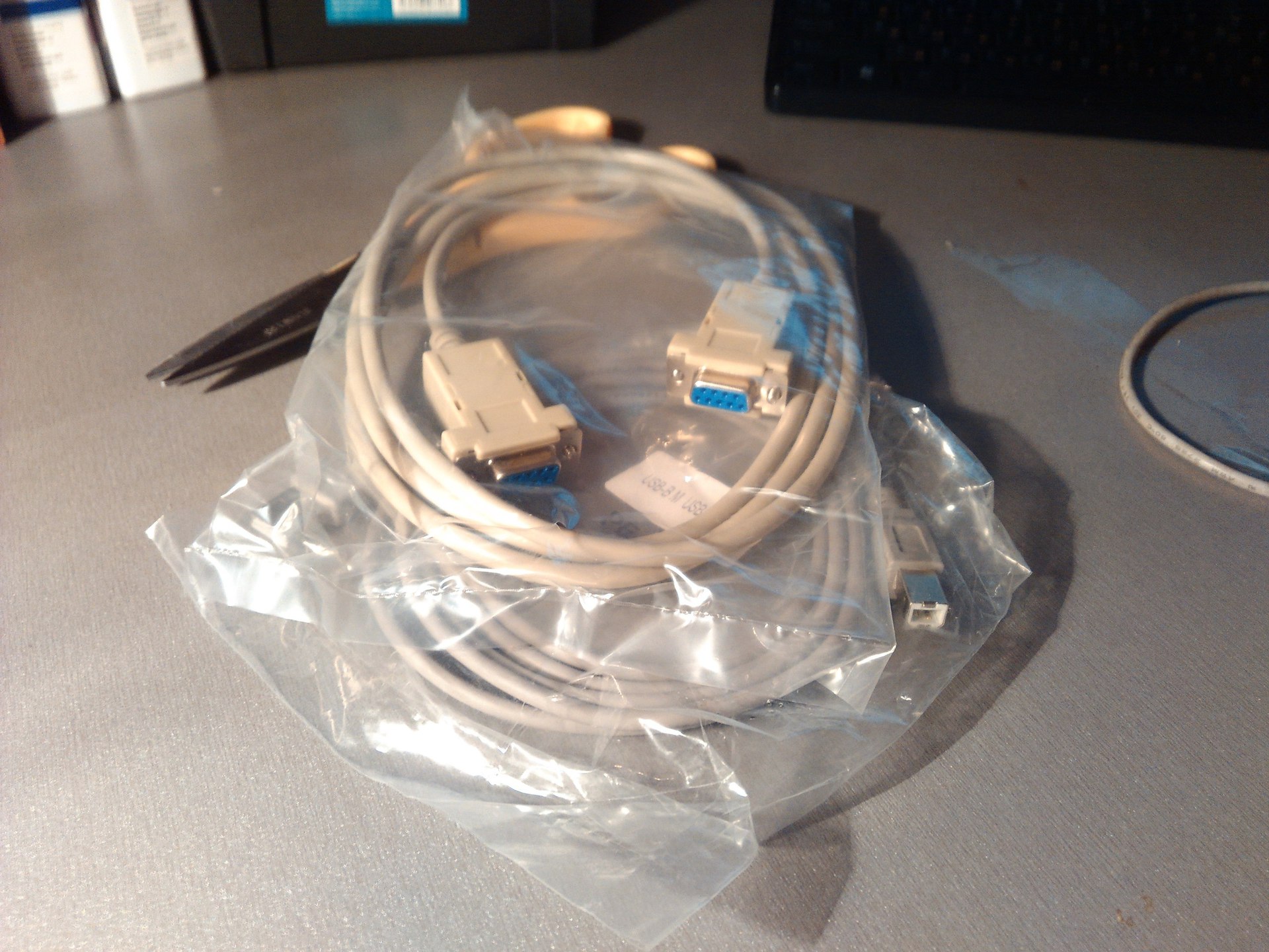
Let's go through the rest of the kit. Included were also COM-COM and USB-A - USB-B cables.
The JTAG MT-LINK programmer was also sent:
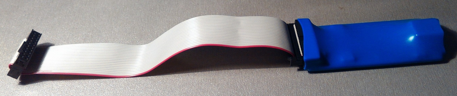
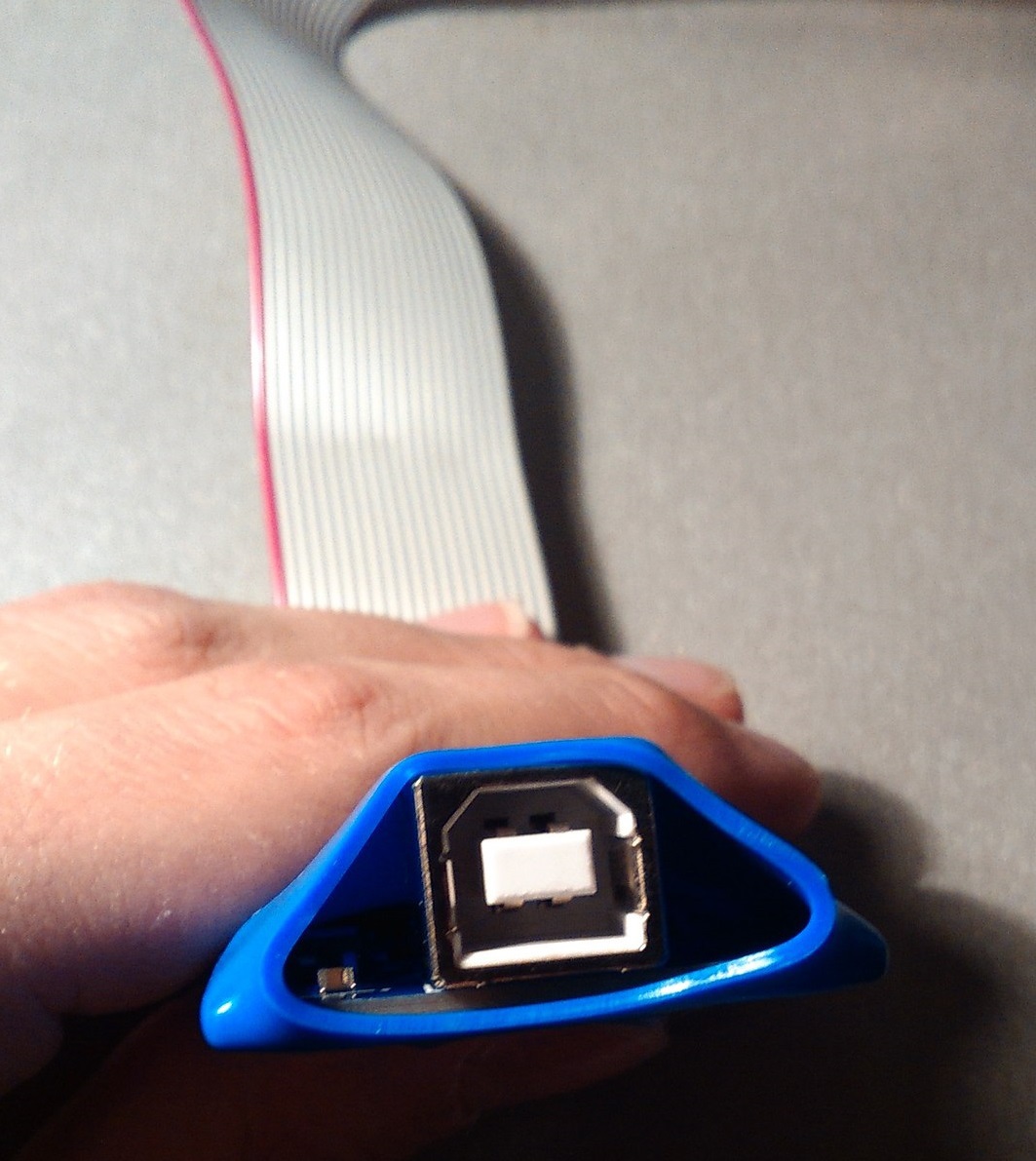
Again, a thick board in an even more toast “vestment”. After connecting the programmer to the computer on the board, the LEDs flash. But you can only see them by looking through the slot near the USB port ... I did not dare open the insulation. So be it. More reliable.
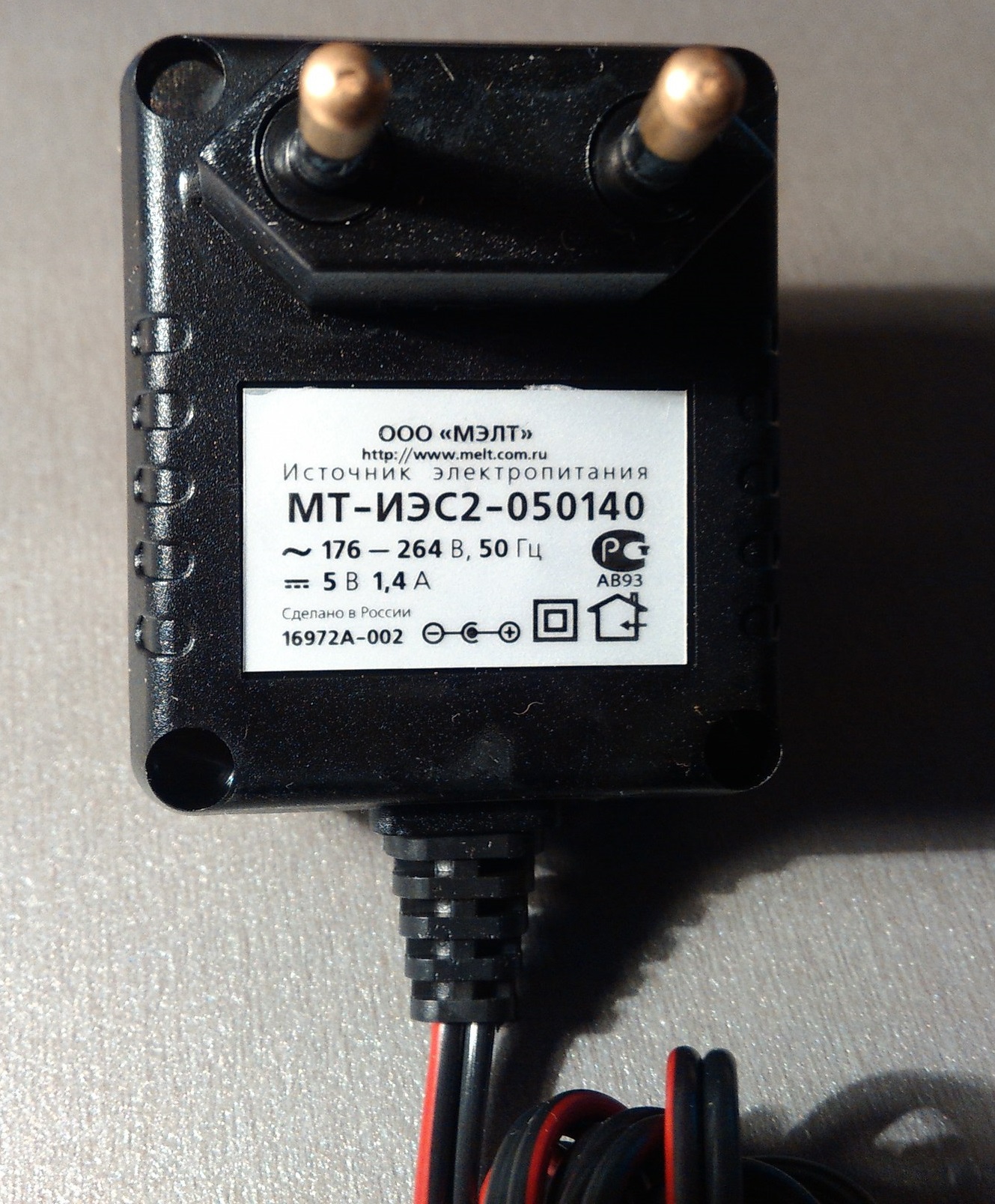
Well, it remains to mention the power supply:

Connection
Well, I think, it’s time to connect all of this and plug it into the network. Speaking of nutrition. If you connect the JTAG, the screen starts to glow dimly, but if you connect the power, the brightness becomes maximum. Also when turned on, the red LED lights up. Near the LED and the lower COM port there is a jumper, signed as “POWER_SEL”. In order for the power to come through the power supply, you need to remember to switch it in the state of 2 right closed contacts. At first, I expected to see something like a greeting, but not destiny ... Apparently, the controller was salted clean.

Customization
Next was what I spent about three hours. It was necessary to sew the test program from the disk in the MK using keil 5. I have been searching for all the necessary files for a long time so that everything works. Part of it had to be taken from the company's server, since they were not on the disk that came with it.
1. First we need to download from the official site : “Software pack for Keil MDK 5 (MDR32F9Qx, MDR1986VE1T, MDR1986VE3T)”, unpack and install. Immediately say. With keil 4, this file does not survive. Only keil 5. Although the title says it, but I had hope for compatibility ...
2. Next, you need to install 2 files: “Setup_JLinkARM_V468a” and “MT-Link”. These are the drivers for the MT-LINK programmer. They are not on the disk, so I filled them at the end of the article. They were provided to me by an official representative by e-mail.
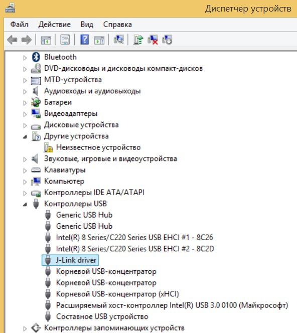
3. After these actions we connect MT-LINK to the computer, the device should be determined, but just in case we go to the device manager and check if the drivers are up.
4. In addition to the heap of advertising and documentation for the rest of the company’s products, along with, of course, the demo video, the disk that comes with the bundle contains the “Software and Hardware” archive at the root of the disk. From it, on the way “software and hardware \ software and hardware \ debugging and demo payments”, you need to unpack the folder “Debugging board 1986E92U, 198692QI (MDR32F9Q2I)”.
Here is a list of all the files that are needed in the process:

In the unpacked folder, we can see the following:

5. From here we should copy the file “MDR32F9x.FLM” to the “Flash” folder in the directory with keil 5. I have (by default) a path like “C: \ Keil_v5 \ ARM \ Flash”.
6. From the software folder, copy the “Test Progs” folder to the root of the disk. As it turned out later, if there are Russian characters in the file path, the project is not compiled and refuses to be stitched into the controller.
7. Connect the programmer to JTAG_A (upper port) and set the corresponding position on the boot BOOT levers (uppermost to the left, lower two - to the right). Connect the power. Do not forget to switch the power source selection lever.
8. Now go to keil 5.
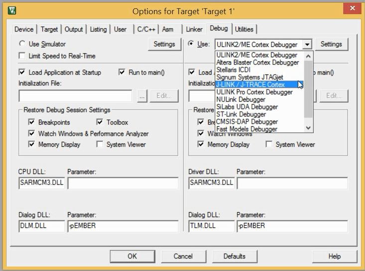
9. Go to Project -> "Options for Target"

10. There we select the Debag tab, click on the “Use” circle in it, then choose J-Link next in the list, then click “Settings”.
11. Next, go to the Debag tab. At once I will say that the number of the programmer should be immediately shown in the “SN:” field. If not, then something is wrong with the drivers. Next in the “PORT” list, you need to change the JTAG to SW and select the frequency in the list next to 1MHz. In theory, you can up to 3, but for now you can stop at one. After that, the microcontroller code should appear on the right, as in the picture. If nothing appears, then you need to check the correctness of the selected mode on the board, press the "RESET" button and select the frequency again. If it does not help, then check how the controller is installed in the crib. Often enough to just press it to the legs "moved away" and "stood up" back. Then again press “RESET” to select the frequency.

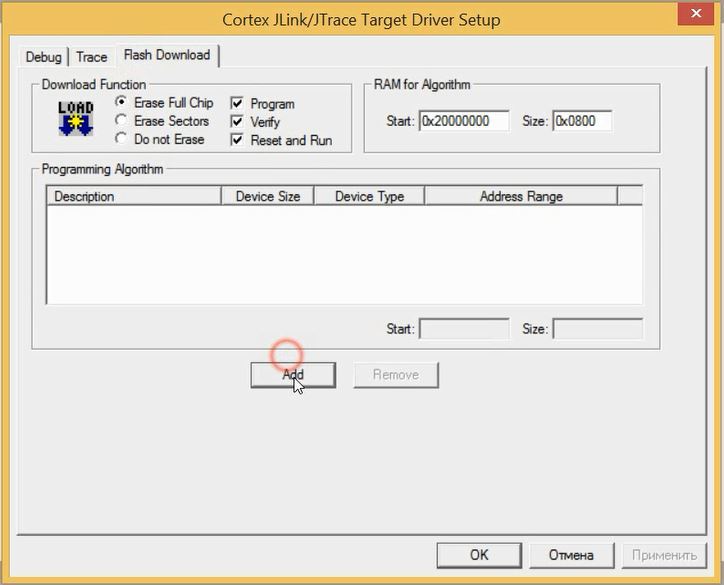
12. After successful recognition of the controller, go to the “Flash Download” tab. There we put the bird near the "Erase Full Chip", as shown, and click Add.
13. From this list, select our microcontroller and click OK. If there is no microcontroller, it means that you did not copy the FLM file to the Flash folder at the beginning.

This completes the setup. Now go to the folder "C: \ Test Progs \ EV1986BE92_Rev2_Test" and run the project. When enabled, 2 errors will pop up. Just click OK.

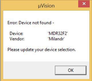
14. Next we will come again to make a small adjustment. Go to Project -> "Options for Target". And in the item Device choose our micron. Click OK and go there again.

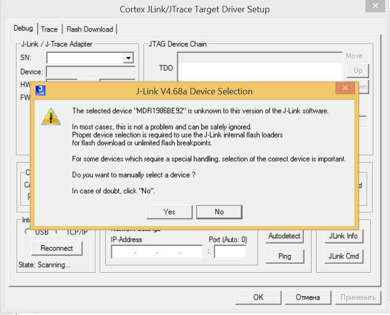
15. Further, in the Debug tab, we check that all the parameters we previously set match. If something is wrong - fix it. Most likely you have to re-configure everything. But it will not be difficult. When setting up the programmer, this error may occur. Just click No. Further we configure everything according to the old scheme. Do not forget about the Flash Download tab. Then click "OK".
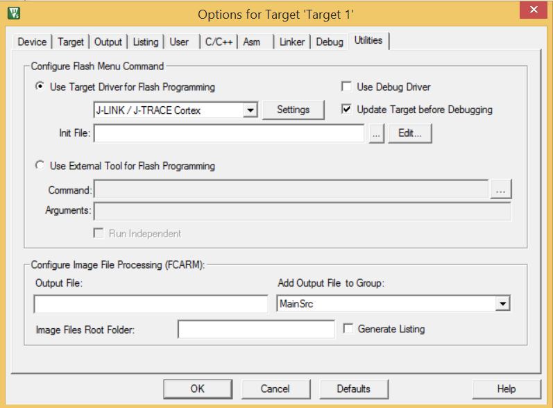
16. Next, go to the Utilities tab, put a dot to the left of Use Target Driver for Flash Programming, then choose our J-LINK. And finally click Settings. There everything should be already configured the same way as in the previous menu. But still check. Well, that's it.
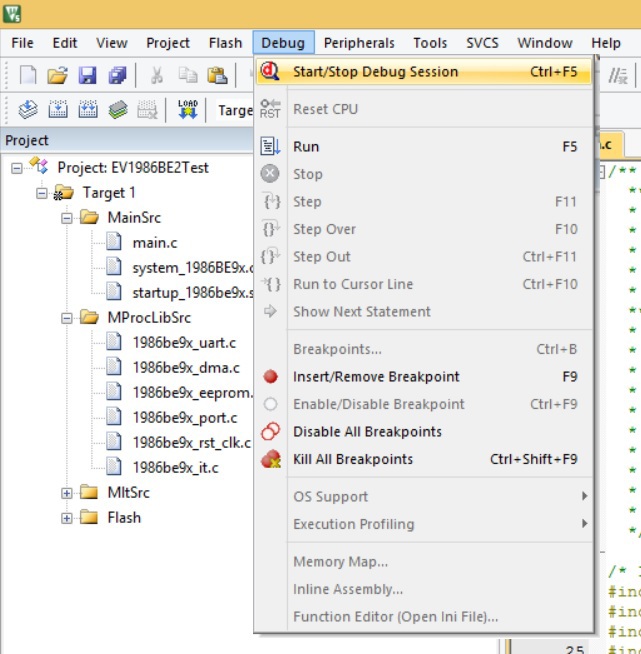
Now we can sew the demo project into the controller. To do this, in the main window we translate into the Debug tab, and in it we select the topmost Start / Stop Debug Session item. Well, or just press Ctrl + F5.
After that, in the lower left corner should run the program download line.
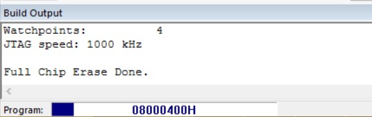
Upon termination the warning will fly out that this version is demo. Click OK and see.
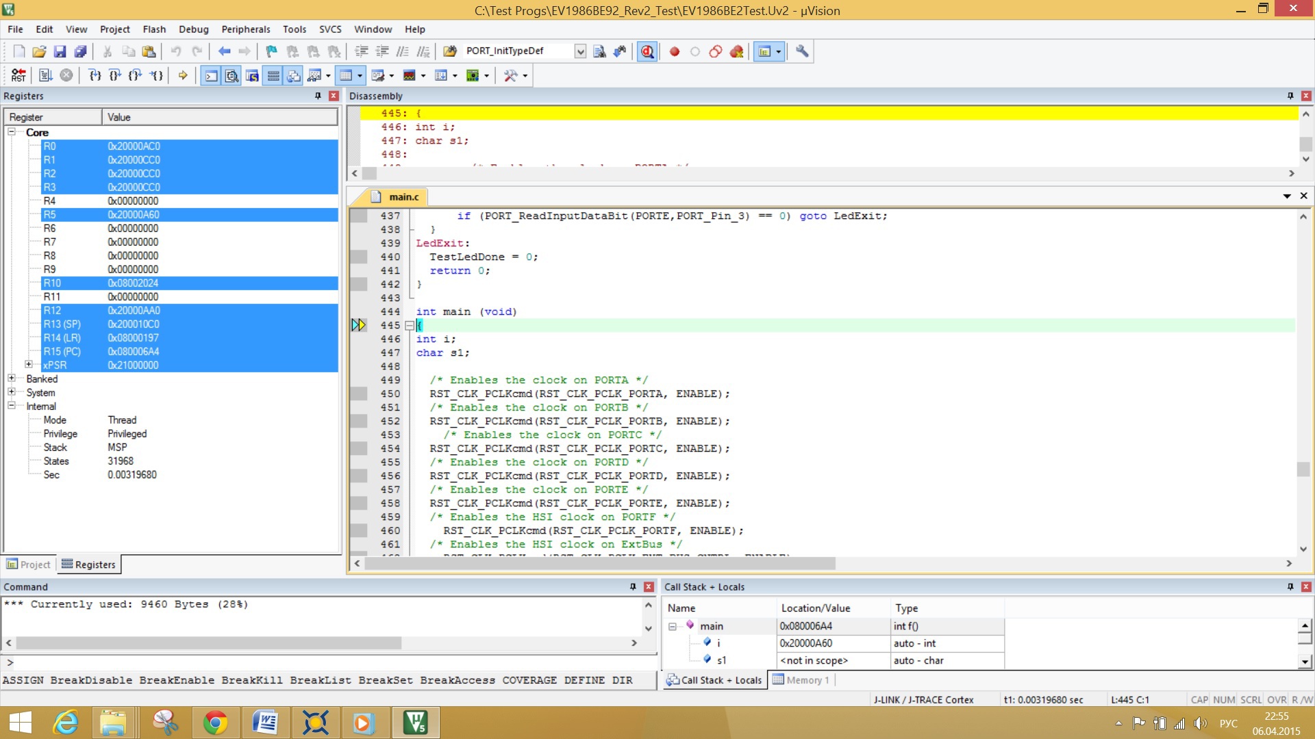
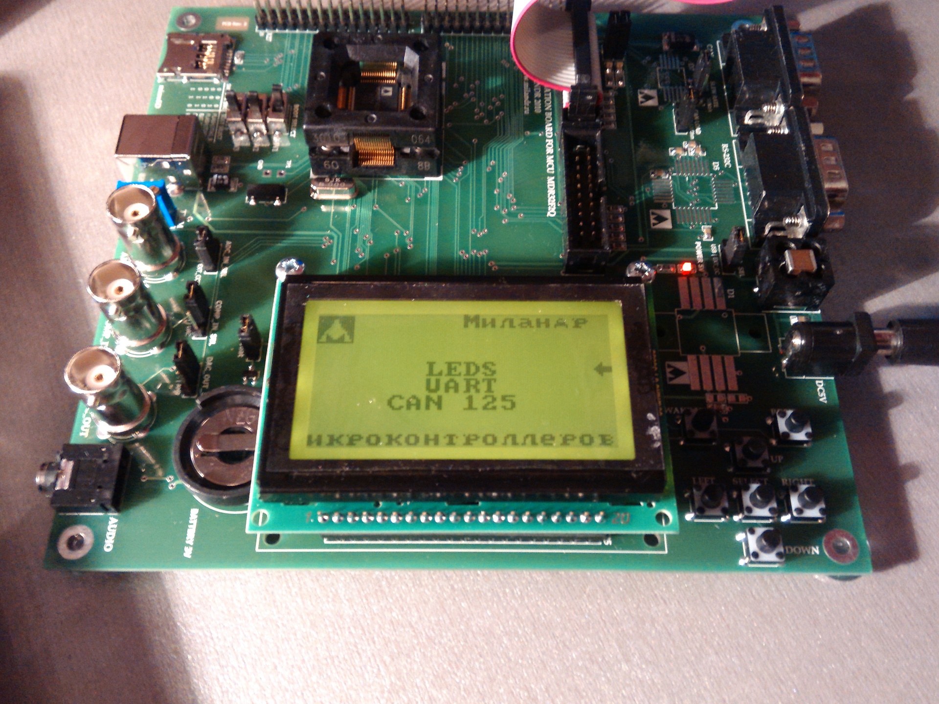
This is a sign that everything went well. You can turn off debugging and look at the execution code. To do this, go back to Debug -> Start / Stop Debug Session. And we can look at what happened with us. The red LED near the JTAG cable should have turned on. Yes, yes) All. Nothing more can be seen. BUT! There is 1 project in the folder. Run it. We configure it as the previous one, BUT. For inexplicable reasons, DO NOT select a controller. There, where we chose MK from the list, there is not a single company, no controller. Clear sheet. But in all other tabs everything is fine. We also configure J-LINK and enable / disable debugging. And we will see it. Further, by controlling the keys, various tests can be included in the menu. So far, I've only been testing LEDs.
Conclusion
In conclusion, I would like to say that in the future I plan to write a series of mini-lessons on mastering this MC and its periphery. Such a quick transition from STM32 to K1986.
Here is the folder with the necessary files .
Source: https://habr.com/ru/post/255199/
All Articles