Moderately Universal Control Device on Raspberry Pi + stratum1 NTP server
Hello.
$ (any picture with accordion)
Disclaimer: I'm aware that there are already 1000 + 1 implementations of stratum1 NTP servers on RasPi. Mine will be a thousand. But still, I really want to tell about it, especially since the result is a device that (a) can be mounted in a rack, (b) performs slightly more tasks than just an NTP server, (c) required some labor, which can be rated by the public
So, the task was set (by myself) as follows: I want to ...
I want to emphasize that the minimum price criterion is not set, spare parts were purchased on the basis of some kind of empirical price acceptability.
Since by profession I (I don’t even know how to formulate it more precisely) is somewhat far from the development of electronics, but very close to building systems on Linux, my choice fell on Raspberry Pi (well, plus I already had experience building such a device on RasPi only chips were slightly less, and wretchedness - a little more). The following components were purchased:
It was decided to connect everything to RasPi as follows:
To output temperature sensors outward, I used the DB9 connector - I need 3 sensors, each with 3 legs. The sensors themselves are connected with a regular telephone 4-wire cable.
')
The result was a good gizmo!
Front view (off):
The case was cut with a Dremel, I think, any model will do. I used an abrasive cutting disc for rough cutting of holes (so what that plastic melts), I used a 180-grit sandpaper for finishing. I also tried to use a thin grinding peak, but it “grinds” round holes in soft plastic without wanting gently round the corners. Disc skin is much better and can even be used for accurate cutting (of course, cutting them as a cutting disc does not work). Well, I also received Dremel from spacers 6 mm high, spacers 3 mm high, but I think this is not a special trick.
Front view (included):
The yellow LED on the right blinks differently depending on whether the GPS module sees satellites or not (the LED is placed on the output of the FIX module)
Inside view:

Bottom left is the RTC module, top right is the GPS module, top left is the RasPi itself, in the center is the “power supply”. The base is made of an acrylic plate wrapped in a non-conductive anti-static bag.
I have written so far a little python script to check that everything works. Library for working with GPIO-extender took here . The backlight of the screen is controlled by 3 pins, one of them under the control of a GPIO expander, the other two I brought to separate GPIOs on the RasPi. For example, the light blue screen:

The screen displays the time, date and temperature from one of the temperature sensors.
But the yellow screen:
The orange button, as is clear from the switching scheme, is normally closed and, when pressed, interrupts the power supply (reset, in short). But what will happen if you press the blue button:
With the blue button, I gave a little blunder. First, it is normally closed, about which I successfully forgot. As a result, we have to catch the appearance of a falling front, and not an ascending one. And secondly, these buttons, as it turned out, rattle terribly. Fortunately, in the rpi.GPIO library this is already provided for and you can set the time during which the callback function will not be called.
I had to tinker a bit with ntpd and rebuild it from source, because the distribution package from Raspbian does not support the PPS source, which is not serious for a cool stratum1 ntp server. Well, at the same time I collected gpsd with JSON protocol support, although there is no sense in it - only the delay grows, through SHM it turns out (obviously) to drive the data much faster. In any case, the device requires a street or very close to the street located antenna, otherwise jitter grows to indecent values and use GPS as a time source becomes impossible. PPS is supported by a module from Raspbian pps-gpio.
Temperature sensors are also supported by the standard w1-therm module. After it is loaded in / sys / bus / w1 / devices, directories with the id of each sensor appear. Each directory has a file w1_slave, reading from which gives us a temperature reading. Beauty.
Out of the box, the device is able to perform the functions of an NTP server and a remote terminal. RasPi is fairly stable, does not fall suddenly and for no reason, which allows it to be used for HLO-control and data collection from UPSs. To work with the screen, button and temperature sensors in the plans, roll a small application that will report this data to Zabbix, or provide Zabbix with the ability to read this data. From crazy ideas, you can dynamically update records with geographic location in the DNS, if someone needs it.
Purely theoretically, instead of 3 temperature sensors, you can connect any other 1-Wire devices, if the switching circuit suits them. Unfortunately, there is only one 1-Wire bus on the RasPi, so all three sensors sit on the same pin, which makes it impossible to simply extend the functionality. However, you can always solder 3 wiring inside and get a slightly different device.
Here is such a thing. Scold.
$ (any picture with accordion)
Disclaimer: I'm aware that there are already 1000 + 1 implementations of stratum1 NTP servers on RasPi. Mine will be a thousand. But still, I really want to tell about it, especially since the result is a device that (a) can be mounted in a rack, (b) performs slightly more tasks than just an NTP server, (c) required some labor, which can be rated by the public
So, the task was set (by myself) as follows: I want to ...
- some device could be an NTP server, even in the absence of communication with the Internet;
- the same device could act as a terminal server or as a device for collecting data from a UPS via USB;
- the same device could be mounted in a standard 19 "rack;
- the same device had a wired connection to the ethernet network (speed is not critical - all the same, the console ports are configured at 9600);
- the same device could measure temperature in a rack.
I want to emphasize that the minimum price criterion is not set, spare parts were purchased on the basis of some kind of empirical price acceptability.
Since by profession I (I don’t even know how to formulate it more precisely) is somewhat far from the development of electronics, but very close to building systems on Linux, my choice fell on Raspberry Pi (well, plus I already had experience building such a device on RasPi only chips were slightly less, and wretchedness - a little more). The following components were purchased:
- Raspberry Pi Model B + itself (RasPi2 is an overhead resource, and more expensive);
- MeanWell PS-05-5 “power supply unit” (I checked earlier that 1A is enough to power the whole simple circuit);
- Adafruit GPS module on board (not bare, because I am still learning how to solder, not up to SMD and BGA);
- Adafruit RTC-module on the board, based on DS1307 (it’s not a good NTP server to reset the clock every time it is rebooted);
- Perma-proto HAT for RasPi by Adafruit;
- 16x2 character LCD-display (there was no monochrome, I had to take it with RGB backlighting, in the end it came in handy);
- I2C GPIO Expander for display;
- digital temperature sensors DS18B20;
- 19 "1U plastic case;
- all sorts to taste.
It was decided to connect everything to RasPi as follows:
- GPS module - via UART (console with / dev / ttyAMA0 was removed);
- RTC module - according to I2C;
- display (via GPIO-expander) - according to I2C;
- temperature sensors - 1-Wire (obviously);
- all the rest is free GPIO to taste.
To output temperature sensors outward, I used the DB9 connector - I need 3 sensors, each with 3 legs. The sensors themselves are connected with a regular telephone 4-wire cable.
')
The result was a good gizmo!
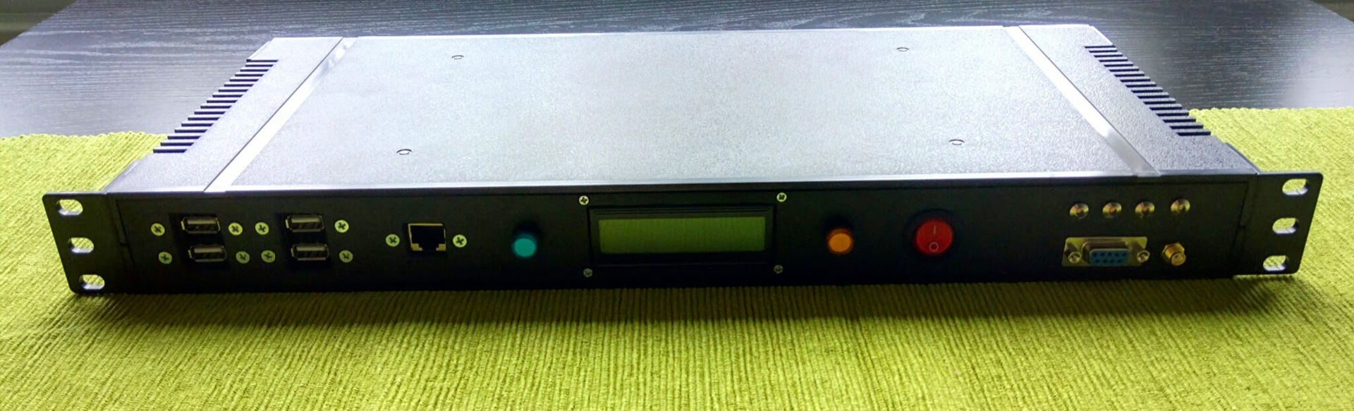
Front view (off):
The case was cut with a Dremel, I think, any model will do. I used an abrasive cutting disc for rough cutting of holes (so what that plastic melts), I used a 180-grit sandpaper for finishing. I also tried to use a thin grinding peak, but it “grinds” round holes in soft plastic without wanting gently round the corners. Disc skin is much better and can even be used for accurate cutting (of course, cutting them as a cutting disc does not work). Well, I also received Dremel from spacers 6 mm high, spacers 3 mm high, but I think this is not a special trick.
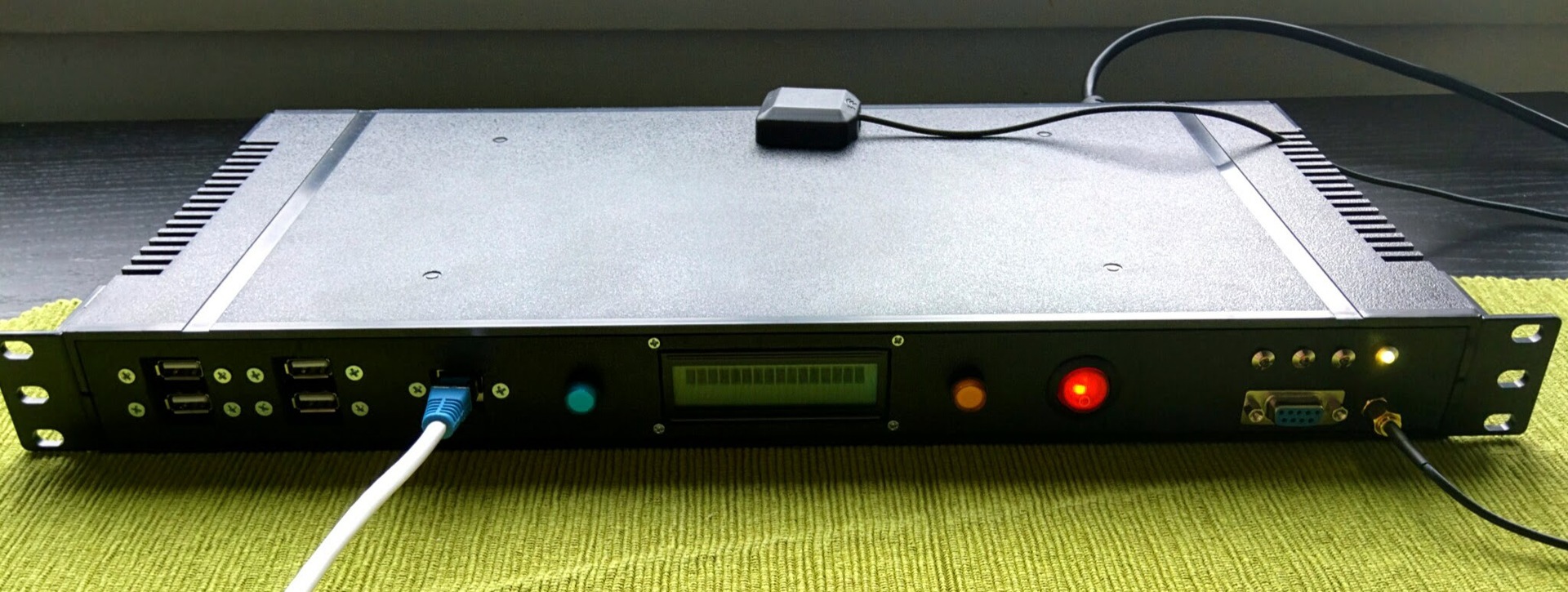
Front view (included):
The yellow LED on the right blinks differently depending on whether the GPS module sees satellites or not (the LED is placed on the output of the FIX module)
Inside view:
Bottom left is the RTC module, top right is the GPS module, top left is the RasPi itself, in the center is the “power supply”. The base is made of an acrylic plate wrapped in a non-conductive anti-static bag.
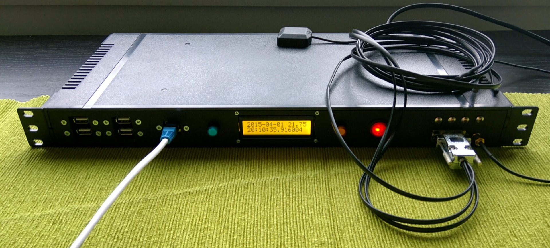
I have written so far a little python script to check that everything works. Library for working with GPIO-extender took here . The backlight of the screen is controlled by 3 pins, one of them under the control of a GPIO expander, the other two I brought to separate GPIOs on the RasPi. For example, the light blue screen:
The screen displays the time, date and temperature from one of the temperature sensors.
But the yellow screen:
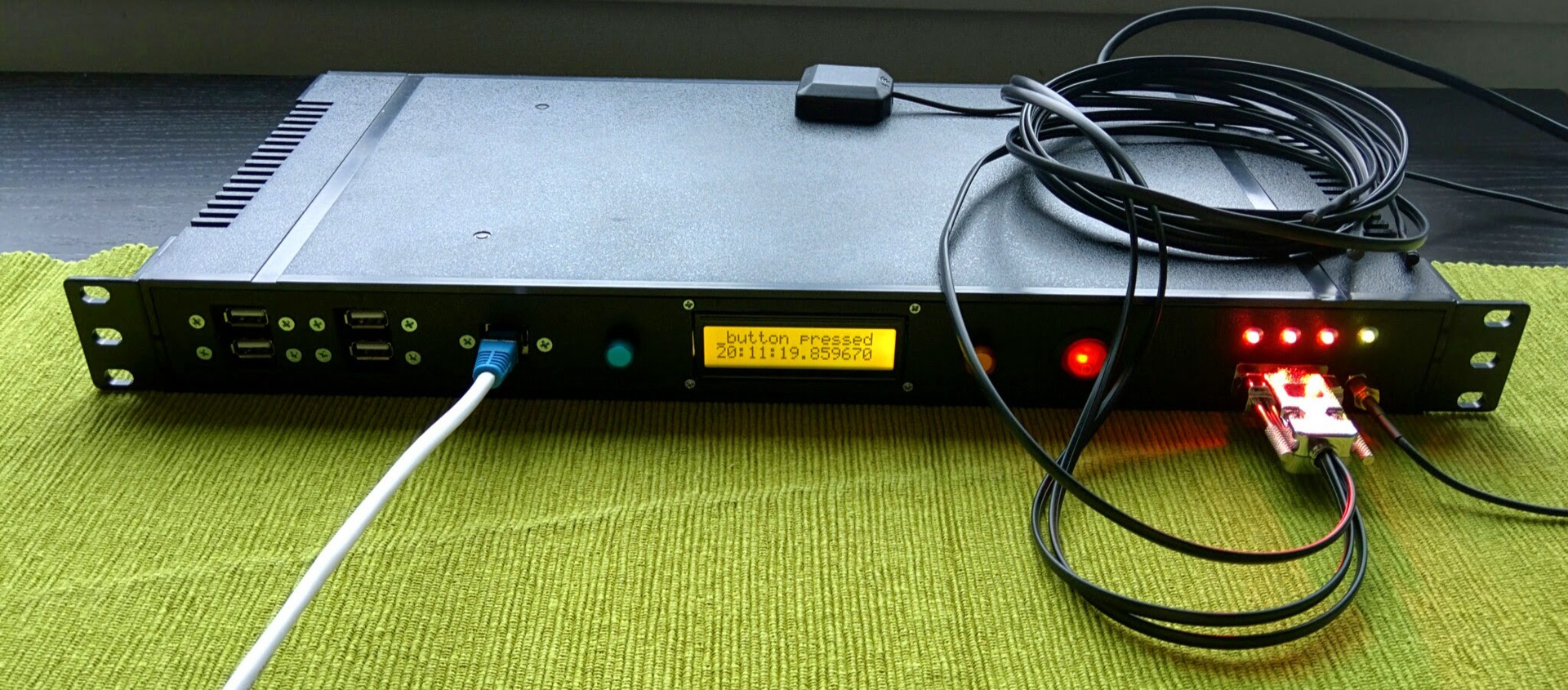
The orange button, as is clear from the switching scheme, is normally closed and, when pressed, interrupts the power supply (reset, in short). But what will happen if you press the blue button:
With the blue button, I gave a little blunder. First, it is normally closed, about which I successfully forgot. As a result, we have to catch the appearance of a falling front, and not an ascending one. And secondly, these buttons, as it turned out, rattle terribly. Fortunately, in the rpi.GPIO library this is already provided for and you can set the time during which the callback function will not be called.
I had to tinker a bit with ntpd and rebuild it from source, because the distribution package from Raspbian does not support the PPS source, which is not serious for a cool stratum1 ntp server. Well, at the same time I collected gpsd with JSON protocol support, although there is no sense in it - only the delay grows, through SHM it turns out (obviously) to drive the data much faster. In any case, the device requires a street or very close to the street located antenna, otherwise jitter grows to indecent values and use GPS as a time source becomes impossible. PPS is supported by a module from Raspbian pps-gpio.
Temperature sensors are also supported by the standard w1-therm module. After it is loaded in / sys / bus / w1 / devices, directories with the id of each sensor appear. Each directory has a file w1_slave, reading from which gives us a temperature reading. Beauty.
Out of the box, the device is able to perform the functions of an NTP server and a remote terminal. RasPi is fairly stable, does not fall suddenly and for no reason, which allows it to be used for HLO-control and data collection from UPSs. To work with the screen, button and temperature sensors in the plans, roll a small application that will report this data to Zabbix, or provide Zabbix with the ability to read this data. From crazy ideas, you can dynamically update records with geographic location in the DNS, if someone needs it.
Purely theoretically, instead of 3 temperature sensors, you can connect any other 1-Wire devices, if the switching circuit suits them. Unfortunately, there is only one 1-Wire bus on the RasPi, so all three sensors sit on the same pin, which makes it impossible to simply extend the functionality. However, you can always solder 3 wiring inside and get a slightly different device.
Here is such a thing. Scold.
Source: https://habr.com/ru/post/255179/
All Articles