We collect your own smartphone
This guide describes, from start to finish, the construction of your own smartphone. It starts with printing on the 3D printer of the case, then the printed circuit boards are soldered, the whole thing is assembled, and, finally, the mobile operating system is installed on the smartphone, and using the Python programming language, it becomes your personal. You can read more about this project at the link .
Required skills:
- basic soldering skills;
- familiarity with the Raspberry Pi.
Or:
- A lot of free time and patience.
')
Step 1: Collect the necessary materials
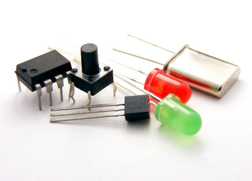
Before we begin, let's order all the components we need. So, you will need the following electronic components and printed circuit boards (in Russia, components can be purchased, for example, in such stores ):
1. Raspberry Pi A + 256MB
2. GSM module Adafruit FONA uFL Version
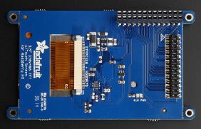
3. 3.5 'PiTFT touch screen
4. Raspberry Pi Camera 5MP
5. Powerboost 500 Basic Converter
6. GSM antenna
7. 1B 8 Ohm speaker
8. USB adapter - Wifi
9. electret microphone
10. 1200mA lithium ion battery
11. 4-40 x 3/8 'screws
12. M2.5 x 5mm screws
13. M2.5 x 20mm screws
14. M2 x 5mm screws
15. slide switch
16. wires
In the meantime, you are waiting for delivery of the order with all of the above, you can print the case.
Step 2: Print the body on a 3D printer
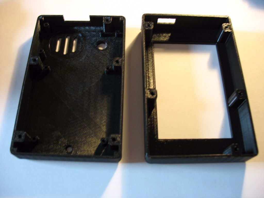
The case of the smartphone consists of two parts printed on a 3D printer: the top and bottom (or front and back, it looks like it look). You can download .stl files from the thingiverse resource. Well, if you do not have a 3D printer, you can order the printing of any company that provides such services (for example, Shapeways). And yes, if you want to make the body more personalized design, you can download the project for Solidworks from my page on github .
Step 3: Main build

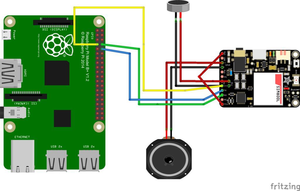
Now let's put everything together. The diagram shows the Raspberry Pi. Instead of connecting directly to it, connect the wire to pin 26 on the PiTFT. Now further.
1. Connect the “bat” contact on the GSM module (Adafruit FONA) to the same contact on the converter (PowerBoost).
2. Solder the wire from the GND terminal (ground) on the GSM module to the same terminal on the converter.
3. Solder the wire from the GND terminal on the converter to one of the half-switch switches.
4. Also connect the GND pin from the transducer to the “ground” of the PiTFT display (The same pinout of the first 26 pins, like that of the Raspberry Pi, note that the arrow and “1” denote the first contact).
5. Connect the 5V line from the transmitter to the 5V line of the display.
6. Solder the wire from the center contact of the slide switch to the “EN” (Enabled) contact on the converter.
7. Solder the wire from the “KEY” pin on the GSM module to pin 12 (GPIO 18) on the display.
8. Place the display over the Raspberry Pi.
9. Recheck all connections!
ATTENTION: While being tested, make sure that the 5V micro USB connector is not connected. The Raspberry Pi is already battery powered.
If you switch the slide switch, the LEDs on the converter should light up and the Raspberry Pi should turn on. The display light should also turn on. If you have configured to send a picture to the display on the Raspberry Pi SD card, then it should be displayed on it. Otherwise, the display will just turn white, which at the moment will also go. Most likely, the LEDs on the GSM module will not light up. To turn it on, hold the power button on it for a couple of seconds. Or, send a signal to the GPIO 18 connector on the Raspberry Pi during the same time. If you managed to power the Raspberry Pi, the display and the GSM module from the battery, it's time to move on to the next step.
Step 4: Final Build
After we connected the power, you can complete the connection of the modules to the Raspberry Pi, as well as connect the speaker and microphone. Let's start.
1. Solder the “spk +” speaker contact (8 ohms) to the “spk -” contact on the GSM module. Polarity does not matter.
2. Solder the red microphone wire to the Mic + contact on the GSM module.
3. Solder the microphone's black wire to the Mic pin on the GSM module.
4. Connect the “RI” contact (Call indicator) on the GSM module to contact 7 (GPIO 4) on the display.
5. Connect the TX on the GSM module to pin 10 (RX) on the display.
6. Solder the GSM RX module to pin 8 (TX) on the display.
7. Connect Vio and bat on the GSM module. If desired, you can use the 3v3 line on the Raspberry Pi.
8. Attach the uFL antenna to the uFL connector on the GSM module.
9. Recheck all connections!
If you try to turn everything on now, the device behavior should be the same as in the previous step. In the next step, we will install a SIM card in the GSM module, which will allow the device to contact the cellular network.
Step 5: Install SIM Card
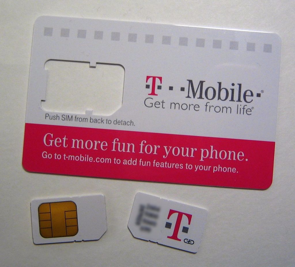
Now that the module connection is complete, you can install a SIM card so that the GSM module can communicate with the cellular network. This module uses 2G networks for data transfer, such as T-Mobile. Please note that the module does not work with 3G and 4G networks. AT & T plans to disable support for 2G networks by 2016, so we will use the T-Mobile SIM card. This GSM module uses a standard format SIM card, so micro or nano SIM cards will not go here. Activate the card according to the operator’s instructions. Then install the SIM card in the GSM module and turn it on. If the red LED of the module blinks every 3 seconds, then it is connected to the cellular network! In the next step, we will install the software so that the Raspberry Pi can communicate with the GSM module.
Step 6: Install an SD Card
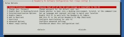
Now that all the hardware has been collected, you can proceed to setting up the interaction of the Raspberry Pi with all this equipment. Start with the latest PiTFT OS firmware on the Raspberry Pi SD card. Click here to download . When the SD card is ready, install it in the Raspberry Pi and turn it on. You will need the raspi-config utility. Here are a few things you need to customize:
1. Expand the file system.
2. Enable camera support.
3. Turn off the serial port. So Raspberry Pi will be able to communicate with the GSM module.
4. Enable ssh. This is important because the Raspberry Pi A + has only a USB port.
Finish the installation and restart Raspberry Pi.
Write startx and Raspberry Pi will launch LXDE on the display. To enter via HDMI, type:
FRAMEBUFFER=/dev/fb0 startx Step 7: Install Wifi
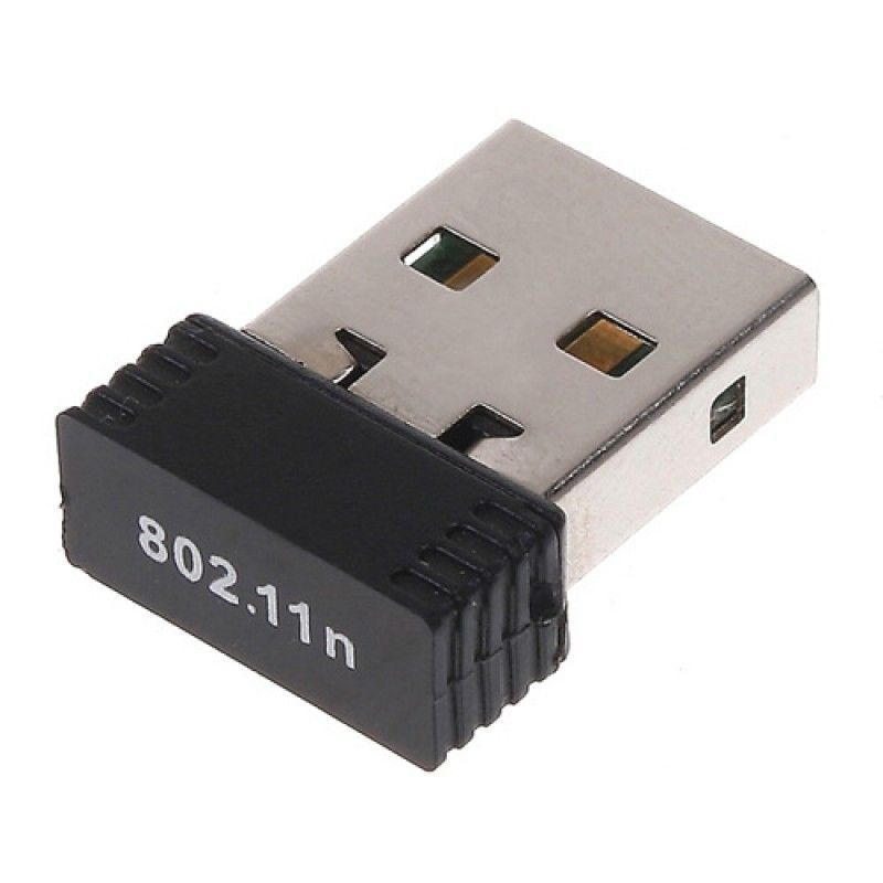
Your phone does not have a keyboard, so to access the device via the console, you need to install wifi to connect via ssh. Connect the Wifi adapter to the computer and configure the connection via Wifi Config. Turn off the Raspberry Pi and connect the Wifi adapter to it. If you still cannot connect to the Raspberry Pi via ssh, try using a USB hub. More information on configuring Wifi can be found here .
Step 8: Final Software Preparation
GSM module testing
To test the GSM module, install minicom with the command:
sudo apt-get install minicom Then run:
sudo minicom -D /dev/ttyAMA0 -b 9600 The terminal should open for interaction with devices via com-port. If you write:
AT in response should receive "OK". If not received, then check all connections. If received, then the GSM module is ready for operation.
Screen rotation
You may have noticed that the text on the screen is shown sideways, and not guided by the position of the phone. Let's change this with the command:
sudo nano /etc/modprobe.d/adafruit.conf Change the value of the "rotate" parameter to 180 in the file.
Finally, to add LXDE to autoload, follow the description in the instructions .
Installing camera software
Now let's install the software that helps to take a photo with a Raspberry Pi camera. To get started, write:
sudo apt-get install python-pip Camera installation:
sudo pip install picamera=0.8 Finally, download the software:
git clone https://github.com/spadgenske/adafruit-pi-cam Step 9: Install TYOS

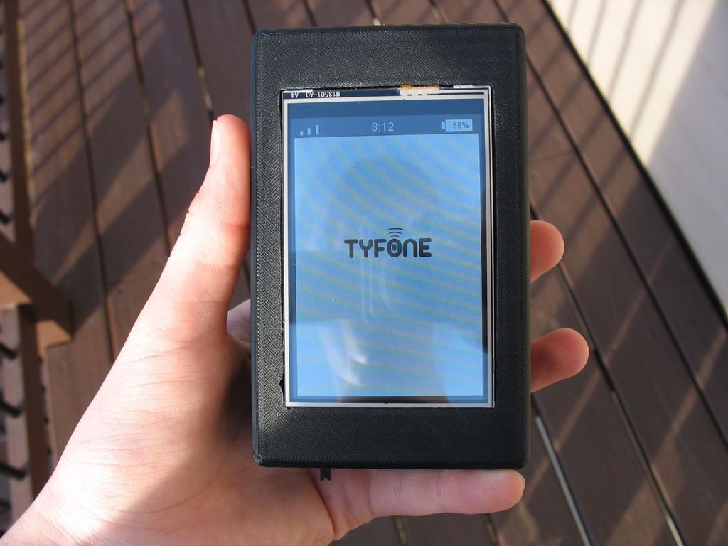
TYOS is an operating system for mobile devices (Technically, a modified version of Raspbian is an operating system, and TYOS is only a graphical shell), enabling the phone to send and receive sms messages, as well as make calls. In the console write:
wget https://github.com/spadgenske/TYOS/archive/0.1.0.zip Unpack the archive:
unzip 0.1.0.zip To run TYOS write:
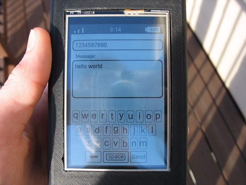
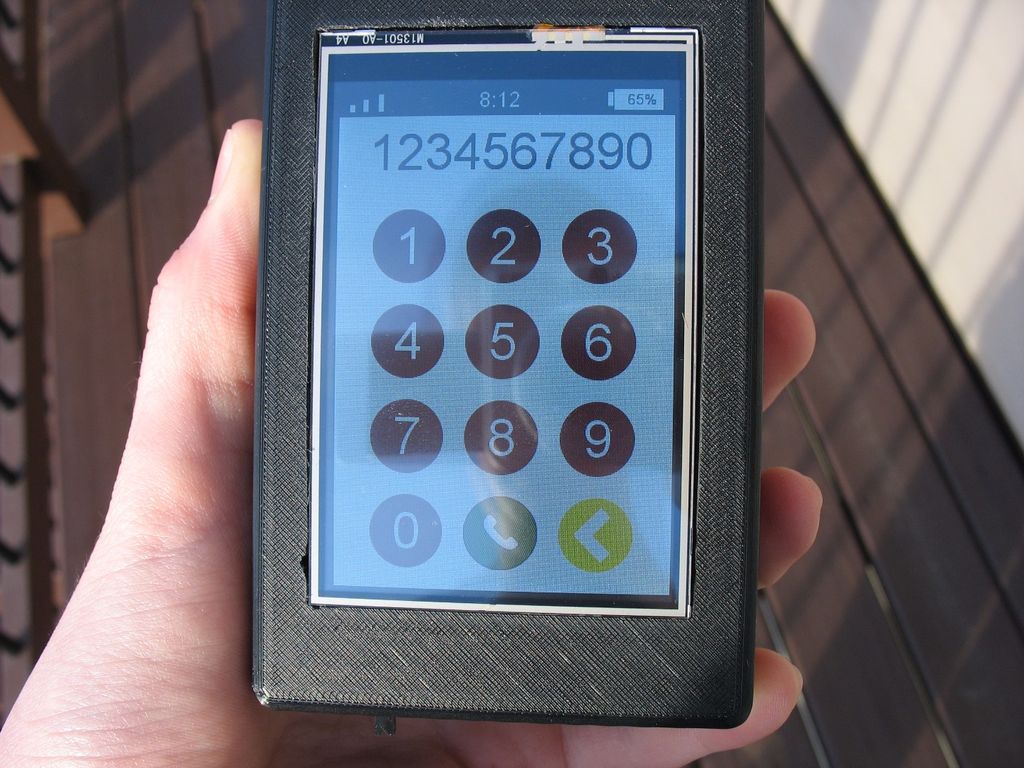
sudo python /home/pi/tyos/src/main.py When TYOS starts, make sure that everything works by sending sms and making a call. When you make sure everything is in order, you can set TYOS to autoload.
Write
sudo nano /etc/rc.local to open the configuration file. At the bottom, after the text and before the line “exit 0”, add the following text:
sudo python /home/pi/tyos/src/main.py --power Now restart the Raspberry Pi. TYOS should start when the device boots!
Step 10: Putting It All Together
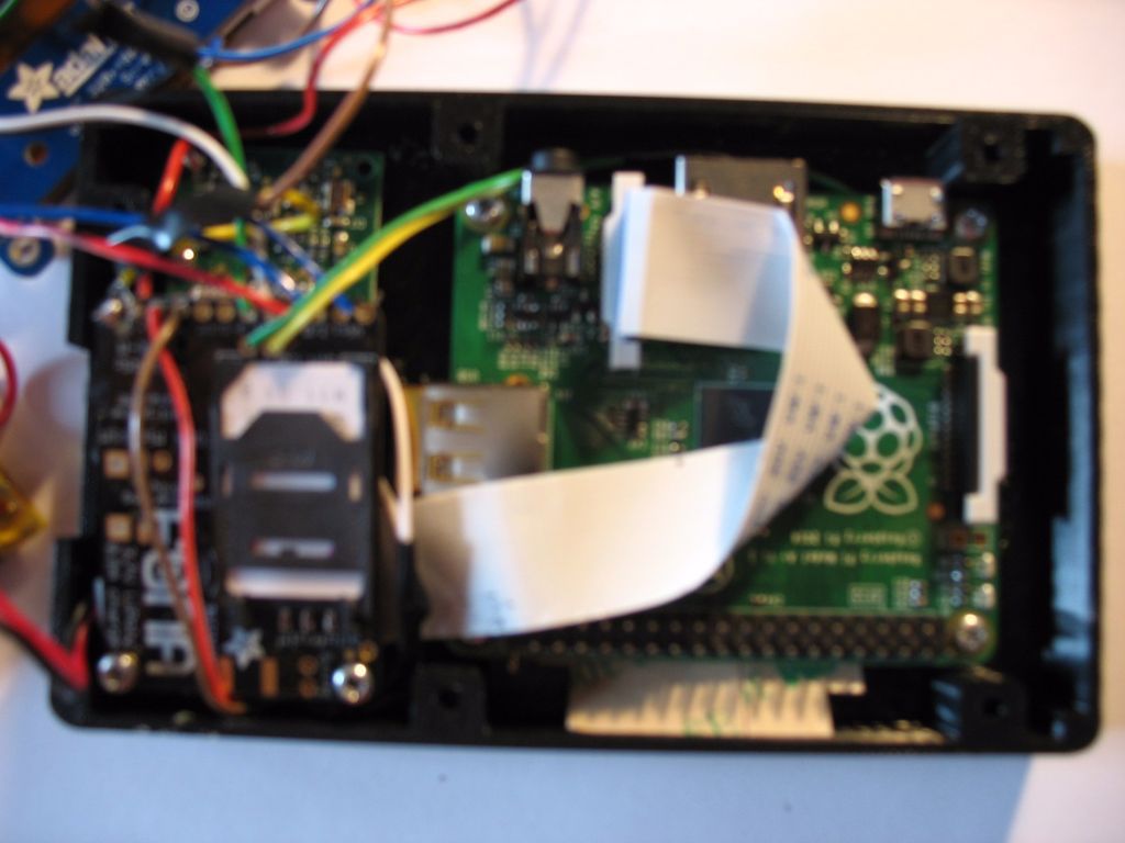
Now you can safely pack everything into the case.
1. Using hot glue, stick the microphone and speaker into the connectors for them.
2. Using M2 screws, fasten the camera. You will need to connect a camera and a Raspberry Pi with a ribbon cable, so position it appropriately.
3. Using the M2.5 screws, fasten the Raspberry Pi along with the installed SD card and Wifi adapter to the bottom of the case.
4. Attach the camera ribbon cable to the Raspberry Pi.
5. Also using M2.5 screws, fasten the GSM module with the SIM card into the case.
6. When laying the wire, make sure that they do not interfere with any other electronics.
7. Wrap the transducer with tape to avoid a short circuit.
8. Place the converter and battery between the Raspberry Pi and the display.
9. Using hot glue, glue the slide switch to the connector for the top of the case.
10. Using screws 4-40, connect the top and bottom of the case together.
11. Check all connections.
My congratulations! You have just collected your own smartphone! If you don’t like a phone called “tyfone”, you can change the logo in /home/pi/tyos/graphics/logo.png to whatever you want.
Source: https://habr.com/ru/post/255047/
All Articles