What is under the hood of a dynamic magnetic strip?
Introductory
Time does not stand still - it flows and changes. Technical progress dictates its own rules of life. One of these rules is the presence of the most important tool of everyday life - a plastic card. Credit, settlement, deposit, business cards, club, loyalty cards - now no civilized society can do without them. But what to do if there are too many of these “generally accepted tools of human life”? What if from their excess your favorite wallet starts to burst at the seams? Today we will talk about how this problem can be avoided. Namely, how to turn a few cards ... into one.
Some theory
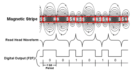
How is information stored? Yes, very simple. In fact, a magnetic strip is a sequence of small sections magnetized in opposite directions. At the place of transition between the areas, the magnetic field strength changes dramatically. It is this change in the magnetic field that captures the magnetic head, which slides along the strip when you swipe a card. Due to a sharp change in the magnetic field, an electromotive force (electromotive force) arises in the head coil, in other words, a voltage pulse appears, which is then amplified and transmitted further.
To distinguish between zeros and ones, the so-called F / 2F coding is used: that is, the F frequency is used for zero coding, and the 2F frequency is used for the one. For example, at the beginning of the track we have several zeros serving for synchronization, then the decoder roughly calculates the frequency F (in particular, the time of one half period is T), and if the pulse occurred after the time T expired, then we are dealing with zero in the middle of this time and at the end (twice the frequency), this is a logical unit.
')
This method is based on the principle that we can not instantly change the speed of the wire card 1.5 times. Due to the fact that we have an impulse at the end of each bit, we can adjust the time T without fear of a smooth change in speed. Otherwise, it threatens to synchronize.
Each card with a magnetic stripe always has 3 tracks. Another thing is that they are not always used.
| 1st track | ALPHA format | 79 characters | 7 bits per character | 210 bit per inch |
| 2nd track | BCD format | 40 characters | 5 bits per character | 75 bit per inch |
| 3rd track | BCD format | 107 characters | 5 bits per character | 210 bit per inch |
In the case of discount cards, only the second track is most often used, due to the fact that it has the smallest recording density, and, as a result, the highest resistance to interference in the form of stuck substances, scratches or even cracks. Usually, there is recorded the numerical identifier of the carrier of the card, which, just in case, is duplicated on the front of the card itself.
In the case of bank cards, the first and second tracks are used. The meaning of the data is known only to the banks.
The third track in the overwhelming number of cases is not used.
The physical width of the information track is 2.8 mm.
BCD format
| b1 | b2 | b3 | b4 | b5 | Character | Function | |
|---|---|---|---|---|---|---|---|
| 0 | 0 | 0 | 0 | one | 0 | (0H) | Data |
| one | 0 | 0 | 0 | 0 | one | (1H) | " |
| 0 | one | 0 | 0 | 0 | 2 | (2H) | " |
| one | one | 0 | 0 | one | 3 | (3H) | " |
| 0 | 0 | one | 0 | 0 | four | (4H) | " |
| one | 0 | one | 0 | one | five | (5H) | " |
| 0 | one | one | 0 | one | 6 | (6H) | " |
| one | one | one | 0 | 0 | 7 | (7H) | " |
| 0 | 0 | 0 | one | 0 | eight | (8H) | " |
| one | 0 | 0 | one | one | 9 | (9H) | " |
| 0 | one | 0 | one | one | : | (Ah) | Control |
| one | one | 0 | one | 0 | ; | (BH) | Start Sentinel |
| 0 | 0 | one | one | one | < | (CH) | Control |
| one | 0 | one | one | 0 | = | (DH) | Field separator |
| 0 | one | one | one | 0 | > | (Eh) | Control |
| one | one | one | one | one | ? | (FH) | End sentinel |
The 5th bit acts as a parity bit.
In the alpha encoding format (where 7 bits per character) it is possible to store numbers, Latin letters and some special characters.
alpha encoding format
| b1 | b2 | b3 | b4 | b5 | b6 | b7 | Character | Function | |
|---|---|---|---|---|---|---|---|---|---|
| 0 | 0 | 0 | 0 | 0 | 0 | one | space | (0H) | Special |
| one | 0 | 0 | 0 | 0 | 0 | 0 | ! | (1H) | " |
| 0 | one | 0 | 0 | 0 | 0 | 0 | " | (2H) | " |
| one | one | 0 | 0 | 0 | 0 | one | # | (3H) | " |
| 0 | 0 | one | 0 | 0 | 0 | 0 | $ | (4H) | " |
| one | 0 | one | 0 | 0 | 0 | one | % | (5H) | Start Sentinel |
| 0 | one | one | 0 | 0 | 0 | one | & | (6H) | Special |
| one | one | one | 0 | 0 | 0 | 0 | ' | (7H) | " |
| 0 | 0 | 0 | one | 0 | 0 | 0 | ( | (8H) | " |
| one | 0 | 0 | one | 0 | 0 | one | ) | (9H) | " |
| 0 | one | 0 | one | 0 | 0 | one | * | (Ah) | " |
| one | one | 0 | one | 0 | 0 | 0 | + | (BH) | " |
| 0 | 0 | one | one | 0 | 0 | one | , | (CH) | " |
| one | 0 | one | one | 0 | 0 | 0 | - | (DH) | " |
| 0 | one | one | one | 0 | 0 | 0 | . | (Eh) | " |
| one | one | one | one | 0 | 0 | one | / | (FH) | " |
| 0 | 0 | 0 | 0 | one | 0 | 0 | 0 | (10H) | Data (numeric) |
| one | 0 | 0 | 0 | one | 0 | one | one | (11H) | " |
| 0 | one | 0 | 0 | one | 0 | one | 2 | (12H) | " |
| one | one | 0 | 0 | one | 0 | 0 | 3 | (13H) | " |
| 0 | 0 | one | 0 | one | 0 | one | four | (14H) | " |
| one | 0 | one | 0 | one | 0 | 0 | five | (15H) | " |
| 0 | one | one | 0 | one | 0 | 0 | 6 | (16H) | " |
| one | one | one | 0 | one | 0 | one | 7 | (17H) | " |
| 0 | 0 | 0 | one | one | 0 | one | eight | (18H) | " |
| one | 0 | 0 | one | one | 0 | 0 | 9 | (19H) | " |
| 0 | one | 0 | one | one | 0 | 0 | : | (1AH) | Special |
| one | one | 0 | one | one | 0 | one | ; | (1BH) | " |
| 0 | 0 | one | one | one | 0 | 0 | < | (1CH) | " |
| one | 0 | one | one | one | 0 | one | = | (1DH) | " |
| 0 | one | one | one | one | 0 | one | > | (1EH) | " |
| one | one | one | one | one | 0 | 0 | ? | (1FH) | End sentinel |
| 0 | 0 | 0 | 0 | 0 | one | 0 | @ | (20H) | Special |
| one | 0 | 0 | 0 | 0 | one | one | A | (21H) | Data (alpha) |
| 0 | one | 0 | 0 | 0 | one | one | B | (22H) | " |
| one | one | 0 | 0 | 0 | one | 0 | C | (23H) | " |
| 0 | 0 | one | 0 | 0 | one | one | D | (24H) | " |
| one | 0 | one | 0 | 0 | one | 0 | E | (25H) | " |
| 0 | one | one | 0 | 0 | one | 0 | F | (26H) | " |
| one | one | one | 0 | 0 | one | one | G | (27H) | " |
| 0 | 0 | 0 | one | 0 | one | one | H | (28H) | " |
| one | 0 | 0 | one | 0 | one | 0 | I | (29H) | " |
| 0 | one | 0 | one | 0 | one | 0 | J | (2AH) | " |
| one | one | 0 | one | 0 | one | one | K | (2BH) | " |
| 0 | 0 | one | one | 0 | one | 0 | L | (2CH) | " |
| one | 0 | one | one | 0 | one | one | M | (2DH) | " |
| 0 | one | one | one | 0 | one | one | N | (2EH) | " |
| one | one | one | one | 0 | one | 0 | O | (2FH) | " |
| 0 | 0 | 0 | 0 | one | one | one | P | (30H) | " |
| one | 0 | 0 | 0 | one | one | 0 | Q | (31H) | " |
| 0 | one | 0 | 0 | one | one | 0 | R | (32H) | " |
| one | one | 0 | 0 | one | one | one | S | (33H) | " |
| 0 | 0 | one | 0 | one | one | 0 | T | (34H) | " |
| one | 0 | one | 0 | one | one | one | U | (35H) | " |
| 0 | one | one | 0 | one | one | one | V | (36H) | " |
| one | one | one | 0 | one | one | 0 | W | (37H) | " |
| 0 | 0 | 0 | one | one | one | 0 | X | (38H) | " |
| one | 0 | 0 | one | one | one | one | Y | (39H) | " |
| 0 | one | 0 | one | one | one | one | Z | (3AH) | " |
| one | one | 0 | one | one | one | 0 | [ | (3BH) | Special |
| 0 | 0 | one | one | one | one | one | ( | 3DH) Special | |
| one | 0 | one | one | one | one | 0 | ] | (3EH) | Special |
| 0 | one | one | one | one | one | 0 | ^ | (3FH) | Field separator |
| one | one | one | one | one | one | one | _ | (40H) | Special |
The 7th bit acts as a parity bit.
Information on the 2nd or 3rd track is stored in the following sequence:
- A certain number of zero bits, about 20;
- The character of the beginning of the data ";";
- the number, or several numbers, separated by the symbol “=”;
- end of data "?";
- LRC (Longitudinal Redundancy Check) - to check the entire message;
- A certain number of zero bits, about 20;
The first track contains a similar sequence except for the data start character "%".
To practice
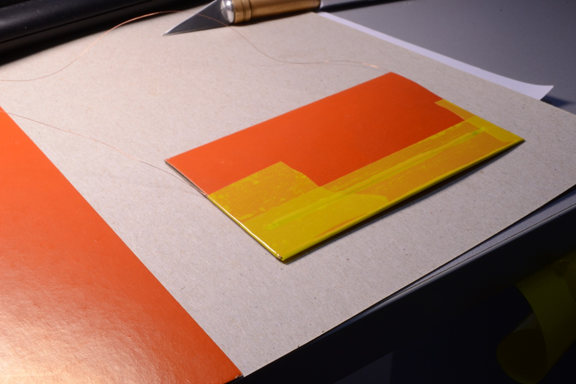
In order to simulate a magnetic strip during a wire with a card, it is necessary to generate a change in the magnetic field near the read head. A simple coil is suitable for this, to which a specially modulated signal will be fed. In order for our simulator card to be pulled, it is necessary to place the coil throughout the entire card. It is also nice that the direction of magnetization coincides with the direction on the card. Here we are lucky: it runs along the long edge of the card and there will be a fairly single-layer coil about the length of a card. To enhance the magnetization as the core, we will use a magnetically soft ferromagnet made of electrical steel (transformer core). The shape of the core is rectangular; The flat side is adjacent to the read head, which makes their interconnection stronger.

In the process of winding will help us screwdriver. It is also desirable to cover the core with lacquer before this in order to exclude the possibility of a short circuit of the coils through the core, otherwise the coil area in the spaces between the closed coils is not effective.
For ease of reading, we will pack our coil in a “case” similar to the shape of a standard plastic card.

Wrap tape.
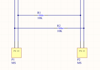
Now let's think about how we will send a signal to the coil. For this we need a driver. Since the output power of the GPIO controller ports is not enough for us, we use the H-bridge type scheme.

MS1 and MS2 are connected to the ports of the controller, output P1 - to the coil.
Capacitors C43 and C44 serve as filters to remove the DC component from the coil. This saves battery power and also controls the steepness of the pulse fronts, which in turn has a positive effect on the magnetic interaction between the coil and the magnetic head (the emf value is directly proportional to the rate of change of the magnetic field).
Install a filter to save the rest of the circuit from the power shots.

To generate pulses at the output of the head, we need to supply impulses in antiphase to the outputs of the coil. To do this, we at the same time change the logic levels on MS1 and MS2 to opposite ones, due to which a double VMS voltage value will be applied to the coil outputs for a short time. Another way is to use only one shoulder of the H-bridge on one side of the coil and the middle point on the other.
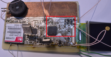
The controller for controlling the circuit is taken with a margin of computing power - STM32F405.
So, the code for the example of the second track:
// : #define STRIPE_2_PIN_P GPIO_Pin_13 #define STRIPE_2_PIN_N GPIO_Pin_14 #define STRIPE_2_PORT GPIOB #define STRIPE_2_RCC_PERIPH RCC_AHB1Periph_GPIOB void stripe_init(void) { GPIO_InitTypeDef GPIO_InitStructure; RCC_AHB1PeriphClockCmd(STRIPE_2_RCC_PERIPH, ENABLE); GPIO_SetBits(STRIPE_2_PORT, STRIPE_2_PIN_P); GPIO_ResetBits(STRIPE_2_PORT, STRIPE_2_PIN_N); GPIO_InitStructure.GPIO_Mode = GPIO_Mode_OUT; GPIO_InitStructure.GPIO_OType = GPIO_OType_PP; GPIO_InitStructure.GPIO_Pin = STRIPE_2_PIN_P | STRIPE_2_PIN_N; GPIO_InitStructure.GPIO_PuPd = GPIO_PuPd_UP; GPIO_InitStructure.GPIO_Speed = GPIO_Speed_50MHz; GPIO_Init(STRIPE_2_PORT, &GPIO_InitStructure); } // : void stripe_2_toggle(void) { GPIO_ToggleBits(STRIPE_2_PORT, STRIPE_2_PIN_P | STRIPE_2_PIN_N); } // : void stripe_2_tx_0 (void) { stripe_2_toggle(); vait_stripe_2_period(); } // : void stripe_2_tx_1 (void) { stripe_2_toggle(); vait_stripe_2_half_period(); stripe_2_toggle(); vait_stripe_2_half_period(); } Functions for transmitting bits are ready.
A more advanced level is to convert the information into a sequence of zeros and ones and begin their sequential transfer (if converting each character at the moment of transfer, this promises a time shift and a violation of the synchronization of the receiving part). But we neglect this for ease of execution.
// void buff_2_to_magnetic(char * stripe_2_buff) { unsigned char i, lrc = 0; for (i = 0; i < 20; i++) { stripe_2_tx_0(); } while (*stripe_2_buff) { for (i = 0; i < 5; i++) { if (*stripe_2_buff & (1 << i)) { stripe_2_tx_1(); } else { stripe_2_tx_0(); } } lrc ^= *stripe_2_buff; stripe_2_buff++; } for (i = 0; i < 5; i++) { if (lrc & (1 << i)) { stripe_2_tx_1(); } else { stripe_2_tx_0(); } } } In case you plan to emulate two or more bands at the same time, it should be noted that due to the different recording density, different time intervals arise between the pulses between the pulses, which will require a corresponding number of time meters to measure. For example, you can use timers or TASK in the operating system.
Research part
- In general, the success of the venture depends on the following factors:
- VMS voltage;
- The number of turns of the coil;
- The diameter of the wire in the coil;
- Cross-section of the core;
- Capacity of capacitors C43 and C44;
- Frequency f;
- Coil distance from the read head;
- Magnetic permeability of the core.
It is worth considering that some parameters are changeable within specific limits, some are dependent on each other.
For example, let's give a different voltage to the coil and find out how its change will affect the result, taking into account the immutability of the other parameters:
| Voltage | Mm response distance | Mm exposure distance | Uneven reading% | Uneven exposure% |
|---|---|---|---|---|
| 2.3 | 0 | 0 | 10% from the ends | 15% from the ends |
| 2.6 | 0 | one | 30% from the ends | 70% from the ends |
| 2.8 | 0 | 2 | 70% | thirty% |
| 2.9 | one | five | 100% | 0% |
| 3 | 2 | 7 | 100% | 0% |
| 3.3 | four | eleven | 100% | 0% |
The triggering distance is the maximum distance at which successful reading occurs (0 when directly touched).
Impact distance - the distance at which the reading is performed, but with an error.
Irregularity of reading - due to the fact that the magnetic core is not closed, at its ends there is a stronger magnetic field.
According to the table, it can be seen that the best result falls on the voltage range of 2.8-2.9 V.
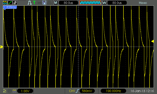
waveform graphs at the ends of the coil depending on the voltage
2.3 In:

2.6 V:
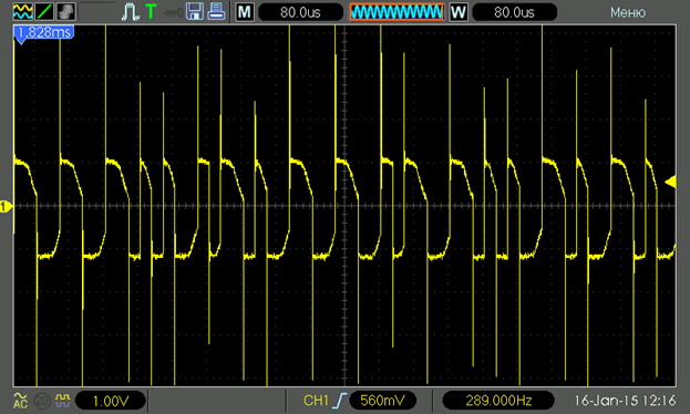
2.8 V:
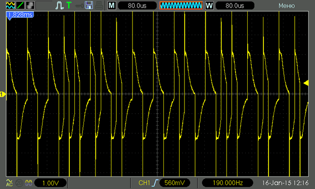
2.9 V:
3 V:

3.3 V:

2.6 V:
2.8 V:
2.9 V:
3 V:
3.3 V:
findings
In the process, there are two drawbacks:
- The influence of the signal of the previous track on the next one;
- Uneven magnetic field intensity along the coil. It manifests itself especially when dragging a card in contrast to its stationary state.
In the first case, the use of additional screens, or a schematic solution in the form of feeding a weakened signal to an adjacent coil in an inverse connection, can help. Thus, the signal and interference will be in antiphase and extinguish each other. Also, additional assistance is provided by the closure of the magnetic circuit.
In the second case, the closure of the magnetic circuit can help, as well as a smooth change in the cross-sectional area of the core closer to the ends of the coil.

Device video:
Github
Source: https://habr.com/ru/post/255033/
All Articles