The story of creating another robot. Part One, Design
In this series of publications, I want to share with you the story of the creation of my first robot under the control of a microcontroller, as well as errors and omissions that I made during the entire process. I will say right away that the software part of the robot has not yet been completed and only part of the functions have been implemented, but I continue to struggle with bugs and laziness and in the future I will definitely finish everything that I had in mind, I ask you not to judge strictly. If I am interested in you - I ask. Part one, design .
Probably, it all started with the fact that I wanted to spend my free time more productively. The decision to build a robot was lightning-fast and unshakable - I always liked articles on the topic of robotics and various DIY, and I also held a soldering iron in my hands and heard about microcontrollers.
The first thing I decided to make a small technical project of the future creation.
After several hours of reflection, an approximate dimensional drawing of the robot was drawn up and the main design requirements were determined:
1) Robot decided to do with two driving wheels and one turning;
2) In terms of size, I wanted to meet the maximum of 200x200 mm, since I always liked small and even miniature robots;
2) Using a PCB as a chassis to reduce overall dimensions seemed like a good idea;
3) All this should be powered by the usual Li-Po battery (a broken helicopter lay in the closet and the battery along with charging I already had).
')
Then it was the turn to determine the functions that the robot should perform :
- Follow the line ;
- Interface for wireless data exchange and control from a computer ;
- Ability to automatically identify and go around obstacles on the way .
Now it was possible to think about the development of a schematic of our future headscarf-chassis. I decided to make a circuit in Altium Designer (since P-CAD and Eagle already knew a bit and wanted to try a new package).
For the first week, I decided on the components and brought them to the Altiuma library, did not strain too much with the 3D models and did them in a hurry, in order to assess the overall dimensions, and not to satisfy aesthetic feelings. Due to the fact that I watched a lot of articles and videos about robots, I had almost no questions about the element base that would perform all the functions listed.
- Motors chose with power from 3-9V, Chinese brands N20 miniature + wheels came complete with motors.
- Engine control on a standard L293D (may not be the best choice, but it was easy to purchase).
- For line sensors , cheap TCRT5000s were selected.
- For the exchange of data with a computer , the well-known Bluetooth module HC-05 is responsible.
- The obstacle detection system wanted to be implemented on the ultrasonic rangefinder HC-SR04 which was planned to be mounted on a conventional 9gr. server
- The brain for the device was also chosen from among the most popular, it was ATmega16A , it completely satisfied the requirements and even with the surplus.
- Slightly looking ahead I will say that even at the design stage of the scheme I decided to score the controller’s free pins by adding a connector for the LCD monitor from Nokia 5110 to the scheme.
By the way, after looking at the wheels, you can see cuts on them, which were obviously made specially.

My thoughts were confirmed by Sparkfun with its own set of the same wheels with optical encoders. Then I got the idea to read the number of revolutions of the wheels (at least approximate).
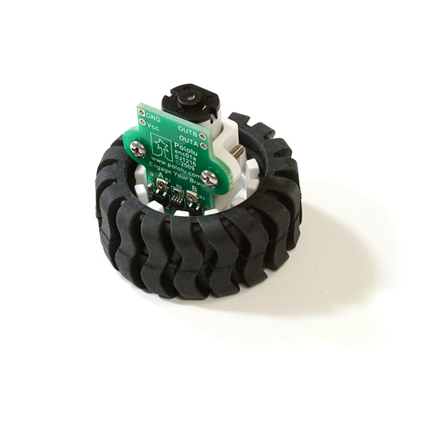
But do not buy another set of wheels, this is not ours! I decided to make my version of the encoder. Popytytev around the wheels and motors with a caliper, I realized that I would not succeed in repeating the Sparkphan shawl. But what comes to mind if it is inconvenient to use optical encoders in the design - correctly, the magnets and Hall sensors! On ebay, rare-earth magnets of almost perfect shape were found, and US1881 Hall sensors were also ordered there .
There are quite a few articles about connecting and working with all electronic peripherals. Questions appeared when designing the power part of the circuit. I had a Li-po 2S1P battery with a voltage of 7.4V and a capacity of 800 mA / h . The controller, servo, bluetooth module and ultrasonic sensor needed to be powered from 5V, and the LCD monitor was generally gentle and waited for 3.3V from us, but the motor was logical to be powered directly from the battery.
And here I made the first flaw for which circuitry and engineers can beat me. Choosing a 5V power supply stabilizer did not calculate in detail the consumption of all the elements and estimated it at about 300mA, and the existing LT1763 chip on 5V was gathering dust in my closet for a long time and was eager to be sealed in a robot. This LT1763 is a small 500mA linear regulator with a small voltage drop and with an input voltage from 1.8V to 20V.
Well, let's estimate how much the whole circuit, powered by 5V, can consume. Take the maximum numbers:
- The MK core for datasheet should consume 15mA when clocked from 16 MHz, we will use 12 MHz, but we will be guided by the fact that the MK will consume an average of 30mA;
- Serva will be almost without load and ideally consume 150-200mA;
- Logic L293D will take a maximum of 60mA;
- The Bluetooth module in the transmission state consumes no more than 10mA;
- Line sensors in total should consume 15-20mA;
- Ultrasonic sensor in measuring state 15mA;
- The display even with backlight should not eat more than 40mA;
- Hall sensors will take over 10mA;
- Well, we will throw on top 10mA on the buffers and suspenders.
As a result, we get ~ 400mA, but with the inclusion of all technology and maximum consumption, which is extremely unlikely. I would say that the 5V power supply in reality should not be more than 300mA. So the choice of LT1763 cannot be called a mistake, but in any case, in the next version of the robot, I’d better put LT1963 or some kind of DC-DC.
So, it took me a few more days to design our small scheme.

As you can see, I decided to use 8 line sensors and accordingly use all 8 channels of our MC's ADC, thanks to 74HC4051D, I reduced the number of pins needed for igniting the sensor LEDs. To work with the monitor , the buffer SN74LVC245ADW was taken, which should solve the problem with voltage levels. It is powered by a small 150mA linear stabilizer microcircuit with an extremely low voltage drop LTC1844 . Also added Li-Po battery discharge sensors, just in case.
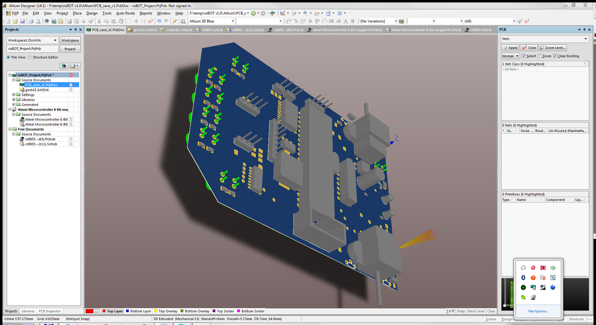
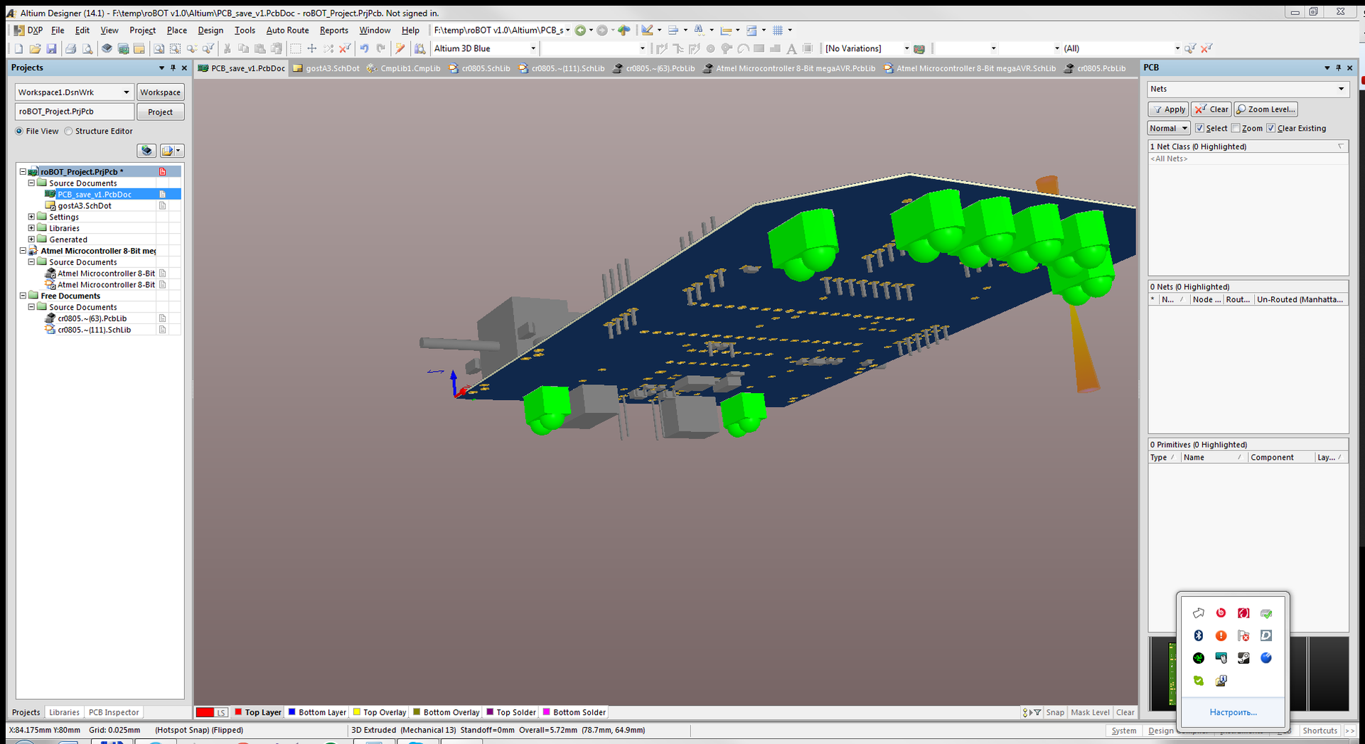
Next, the most “laborious” stage in the manufacture of any electronic device — the creation of a printed circuit board — was waiting for me.
After a few nights of scattering items on the circuit board, something was born:


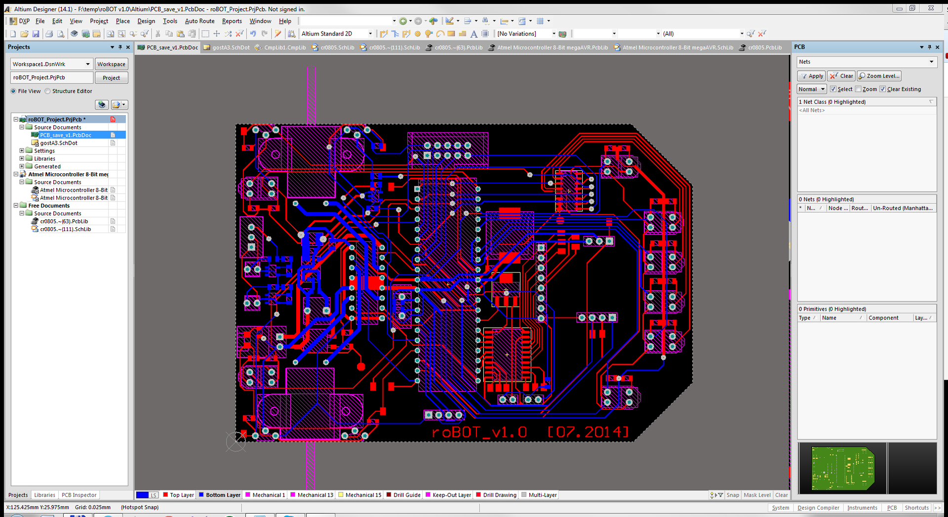
On the whole wiring and dopilku fees took about 2 weeks. As a result, a full-fledged pcb looked acceptable:
With this I finish the first part of my story. I hope you were interested.
I hope for your constructive criticism on the design and presentation of my habropost. In any case, I will do one or two parts in which the process of creating the printed circuit board will be described, I’ll tell you a little about how the whole robot was going, show you the photo of the finished device, talk about the computer program, and I’ll post a short video of the robot’s work.
Probably, it all started with the fact that I wanted to spend my free time more productively. The decision to build a robot was lightning-fast and unshakable - I always liked articles on the topic of robotics and various DIY, and I also held a soldering iron in my hands and heard about microcontrollers.
The first thing I decided to make a small technical project of the future creation.
After several hours of reflection, an approximate dimensional drawing of the robot was drawn up and the main design requirements were determined:
1) Robot decided to do with two driving wheels and one turning;
2) In terms of size, I wanted to meet the maximum of 200x200 mm, since I always liked small and even miniature robots;
2) Using a PCB as a chassis to reduce overall dimensions seemed like a good idea;
3) All this should be powered by the usual Li-Po battery (a broken helicopter lay in the closet and the battery along with charging I already had).
')
Then it was the turn to determine the functions that the robot should perform :
- Follow the line ;
- Interface for wireless data exchange and control from a computer ;
- Ability to automatically identify and go around obstacles on the way .
Now it was possible to think about the development of a schematic of our future headscarf-chassis. I decided to make a circuit in Altium Designer (since P-CAD and Eagle already knew a bit and wanted to try a new package).
For the first week, I decided on the components and brought them to the Altiuma library, did not strain too much with the 3D models and did them in a hurry, in order to assess the overall dimensions, and not to satisfy aesthetic feelings. Due to the fact that I watched a lot of articles and videos about robots, I had almost no questions about the element base that would perform all the functions listed.
- Motors chose with power from 3-9V, Chinese brands N20 miniature + wheels came complete with motors.
- Engine control on a standard L293D (may not be the best choice, but it was easy to purchase).
- For line sensors , cheap TCRT5000s were selected.
- For the exchange of data with a computer , the well-known Bluetooth module HC-05 is responsible.
- The obstacle detection system wanted to be implemented on the ultrasonic rangefinder HC-SR04 which was planned to be mounted on a conventional 9gr. server
- The brain for the device was also chosen from among the most popular, it was ATmega16A , it completely satisfied the requirements and even with the surplus.
- Slightly looking ahead I will say that even at the design stage of the scheme I decided to score the controller’s free pins by adding a connector for the LCD monitor from Nokia 5110 to the scheme.
By the way, after looking at the wheels, you can see cuts on them, which were obviously made specially.
My thoughts were confirmed by Sparkfun with its own set of the same wheels with optical encoders. Then I got the idea to read the number of revolutions of the wheels (at least approximate).
But do not buy another set of wheels, this is not ours! I decided to make my version of the encoder. Popytytev around the wheels and motors with a caliper, I realized that I would not succeed in repeating the Sparkphan shawl. But what comes to mind if it is inconvenient to use optical encoders in the design - correctly, the magnets and Hall sensors! On ebay, rare-earth magnets of almost perfect shape were found, and US1881 Hall sensors were also ordered there .
There are quite a few articles about connecting and working with all electronic peripherals. Questions appeared when designing the power part of the circuit. I had a Li-po 2S1P battery with a voltage of 7.4V and a capacity of 800 mA / h . The controller, servo, bluetooth module and ultrasonic sensor needed to be powered from 5V, and the LCD monitor was generally gentle and waited for 3.3V from us, but the motor was logical to be powered directly from the battery.
And here I made the first flaw for which circuitry and engineers can beat me. Choosing a 5V power supply stabilizer did not calculate in detail the consumption of all the elements and estimated it at about 300mA, and the existing LT1763 chip on 5V was gathering dust in my closet for a long time and was eager to be sealed in a robot. This LT1763 is a small 500mA linear regulator with a small voltage drop and with an input voltage from 1.8V to 20V.
Well, let's estimate how much the whole circuit, powered by 5V, can consume. Take the maximum numbers:
- The MK core for datasheet should consume 15mA when clocked from 16 MHz, we will use 12 MHz, but we will be guided by the fact that the MK will consume an average of 30mA;
- Serva will be almost without load and ideally consume 150-200mA;
- Logic L293D will take a maximum of 60mA;
- The Bluetooth module in the transmission state consumes no more than 10mA;
- Line sensors in total should consume 15-20mA;
- Ultrasonic sensor in measuring state 15mA;
- The display even with backlight should not eat more than 40mA;
- Hall sensors will take over 10mA;
- Well, we will throw on top 10mA on the buffers and suspenders.
As a result, we get ~ 400mA, but with the inclusion of all technology and maximum consumption, which is extremely unlikely. I would say that the 5V power supply in reality should not be more than 300mA. So the choice of LT1763 cannot be called a mistake, but in any case, in the next version of the robot, I’d better put LT1963 or some kind of DC-DC.
So, it took me a few more days to design our small scheme.
As you can see, I decided to use 8 line sensors and accordingly use all 8 channels of our MC's ADC, thanks to 74HC4051D, I reduced the number of pins needed for igniting the sensor LEDs. To work with the monitor , the buffer SN74LVC245ADW was taken, which should solve the problem with voltage levels. It is powered by a small 150mA linear stabilizer microcircuit with an extremely low voltage drop LTC1844 . Also added Li-Po battery discharge sensors, just in case.
Next, the most “laborious” stage in the manufacture of any electronic device — the creation of a printed circuit board — was waiting for me.
After a few nights of scattering items on the circuit board, something was born:
On the whole wiring and dopilku fees took about 2 weeks. As a result, a full-fledged pcb looked acceptable:
With this I finish the first part of my story. I hope you were interested.
I hope for your constructive criticism on the design and presentation of my habropost. In any case, I will do one or two parts in which the process of creating the printed circuit board will be described, I’ll tell you a little about how the whole robot was going, show you the photo of the finished device, talk about the computer program, and I’ll post a short video of the robot’s work.
Source: https://habr.com/ru/post/255025/
All Articles