Universal Nixie-module on IN-12
Original technical solutions of the past often cause excitement and delight today, and if they do not have a direct modern counterpart, they may well continue to exist - this is how a wild mix of components is born, the age difference of which is tens of years.
Last time I built a chip unit module on AY-3-8912 with a similar feeling. I was extremely pleased with the result, but I note that it is not a finished product. Like the hero of this material, the block of gas-discharge indicators IN-12.
')
The clock on the Inks on Habré appeared more than once (for example, 1 , 2 , 3 ), so the post in the style "Yet another Nixie clock" will not. I will focus on briefly and clearly expounding the idea of the display unit and the features of the implementation.
Operating principle
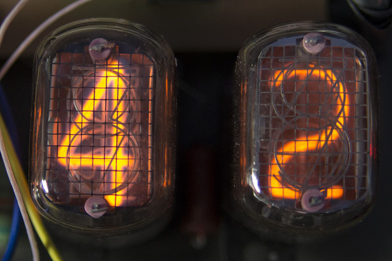
The IN indicators are a glass flask with legs, filled with an inert gas. It contains a package of electrodes (cathodes), made in the form of symbols (in most ID these are numbers). When a voltage of a couple of hundred volts is applied to the selected cathode and the common anode (grid in front of the package), a glow discharge is ignited, the visual manifestation is a red-orange glow near the cathode, repeating its shape.
Control
To control the indicators of the series IN, you need to switch high voltage (current - units milliampere). Life greatly facilitates the existence of the ID1 decoder in the favorite 155th series - they are directly intended to work with the IN indicators. Ordinary decoders can also be used, but then transistors will have to be placed on their outputs. It is an option, but it makes sense only when the K155ID1 is unavailable.
That is, on each indicator we put on a microcircuit. In my case, it turns out 4 pieces. This will be a static indication. To simplify the circuitry, the display is often used dynamically - when at any one time one digit is displayed, but the change occurs quickly, and due to the inertia of human vision, is imperceptible. But such an approach goes against my idea of a universal module, connected to the “head” with minimal expenses (microcontroller, computer, some kind of “raspberry”).
Iteration first, 16 legs.
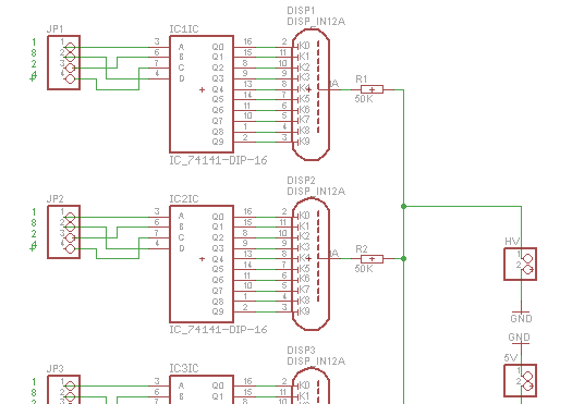
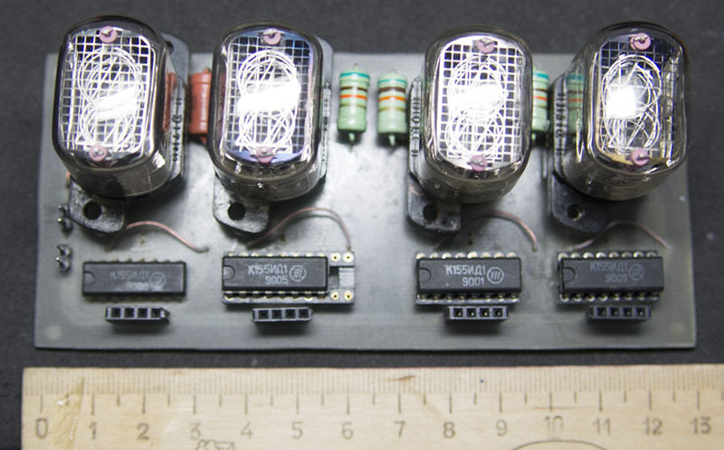
Solve the problem in the forehead. 4 indicators IN-12. For each of them there is one decoder. Anodes through limiting resistors (50 KΩ 0.5 W) are connected to a high voltage source. In my case - a small orphan anode-filament transformer with a diode bridge.
Diluted board, with the use of photoresist is made, the components are installed, you can use. 16 inputs are connected to GPIO Raspberry PI, a simple program is being written that displays the time.
But is it too bold to give so many legs to a four-digit display? I'm not talking about the fact that someone wants to show seconds, and the GPIO “Malinki” is simply not enough. And anyway, where does the Raspberry come in, if for the minimum hours we need the eight-legged ATtiny and DS1307?
Iteration second, 2 legs.
So, we part one more small scarf which will be "the second floor". Two more microcircuits are located on it - eight-bit shift registers 155IR8. They will be a serial to parallel converter.

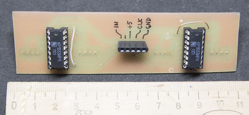

The shift register works as follows: the pulse edge at the clock input (CLK) records the bit register at the information input (A) with a simultaneous shift of the bits already present. Eight register outputs reflect its contents - they are sent to the inputs of two decoders. Two registers are combined into one 16-bit by connecting the last output of one to the input of the other. So, from the device controlling the display module, it is required to output 16 bits (4 bits per indication bit), not forgetting to fix each one with a clock pulse.
So what?
And that's all. There is a basic part of the display module that you can use if you don’t feel sorry for 16 pins. There is an additional fee that reduces the required number of control pins to two. Power - 5 volts and something in the region of 180-220 (2 mA per indicator). You can use a transformer, you can - a pulse converter. It is possible - from the mains voltage through the diode, as recommended in ancient manuals. The last option I was afraid, because I don’t like it when I’m free to walk around the board in an unleashed “network”.
Closer to the finished device
All insights are published on Github. At the moment, there you can see the ready layout of boards (Sprint Layout 6), schemes (Eagle) and program (Python) for Raspberry Pi. The latter is in the process of sawing. At the time of publication, the time display, the effect of randomly scrolling digits (it is necessary to periodically light all the cathodes of the Inca in order to avoid the so-called “poisoning”) is implemented, work has started on the alarm clock. After all, I did not just make a module on AY-3-8912, he will also take part here. I will not describe the pythonium code as part of this material, this is for the third part, devoted to the assembly of Raspberry Pi into one megadevise, the Nixie-indicator and the chip unit module.
Github (main project)
Githab (Chiptyun)
Indicator IN-12
ID1 decoder
Shift register IR8
Source: https://habr.com/ru/post/254901/
All Articles