Description of digital machines on VHDL
Some theory
A digital automat (CA) is a device that receives, stores and converts discrete information according to some algorithm and can be in one of several stable states [7].

Figure 1 - Graph of the digital machine
If the output of a digital automaton depends only on the current state, then such an automaton is called Moore’s automaton, if the output signal depends on the current state and input signals, then this digital automaton is called Mili automaton.
')
The digital automaton can be described using the following representations:
- in the form of a directed graph,
- using transitions and exits.
The representation of a digital automaton in the form of a directed graph is shown in Fig. 1. Here in the circles — the vertices of the graph — the states of the digital automaton are shown, the transitions between the states are shown by arcs between the vertices, and the transition to the same state is shown by a loop.
Near the arcs and loops shows the values of the input signals at which this transition occurs. For example, (a OR b) means that this transition will occur when a = 1 or b = 1 .
The output signals for Moore’s automaton are shown near the vertices of the graph, and for the Miles digital automaton, on the arcs near the input signals. So in fig. 1 shows Moore’s digital automat.
The representation of a digital automaton using tables assumes the existence of two tables: a transition table and an output table. The transition table links the current state, input signals and the future state of the digital automat. The transition table of the CA, described by the graph in Fig. 1, shown in Table. one.
Table 1 - Digital automatic transition table
| Current state | Next state | Transition condition |
| S0 | S0 | a = 0 or c = 0 |
| S0 | S1 | a = 1 |
| S1 | S1 | a = 1 or b = 1 |
| S1 | S0 | a = 0 and b = 0 |
| S0 | S2 | c = 1 |
| S2 | S2 | c = 1 or b = 1 |
| S2 | S0 | c = 0 and b = 0 |
Output table - shows the correspondence of the current state of the digital automat and its output signals (Table 2).
Table 2 - Digital output table}
| Current state | Output |
| S0 | 00 |
| S1 | 01 |
| S2 | ten |
When implementing a digital automaton, we will adhere to the principle of separation into combinational and sequential parts of the circuit. With this interpretation, the digital automaton will be represented by three blocks (Figure 2):
- a combination block of transition logic;
- register for storing the states of the target states;
- combinational output signal generation unit - different for Miles and Moore's CA.

Figure 2 - Schematic representation of a digital machine with asynchronous outputs
The transition logic circuit receives to its input a code of the current state of the digital automaton ( present_st ) and external signals ( input_signal ). The output of this block will be the next state code ( next_st ).
The state register includes three signals: clock ( clk ), reset ( reset ), and the next state code ( next_st ). The clock signal and the reset signal are designed to control the triggers that store the state of the digital automat. On the leading edge of the clock signal, the next state ( next_st ) is recorded in the triggers. The results of writing to triggers appear at the output of the status register as a signal of the current state of the AC ( present_st ).
The output signal shaping unit , depending on the state of the AC (and the input signals for the Miles machine), generates asynchronous output signals. To obtain synchronous output signals, an additional register is added to this block.
Using VHDL to describe digital automata
To describe the state of the digital machine, you must use an enumerated type. For this, a type ( state_type ) is described, the values of which are the states of the digital automaton. Then the signal ( state ) of this enumerated type is described, in which the current state of the automaton will be stored.
TYPE state_type IS (init, state1, state2, ...); SIGNAL state: state_type; Upon implementation, a scheme of several triggers will be obtained. Depending on the state coding method, the number of triggers may vary, which affects the speed and size of the circuit. In more detail about coding methods we will talk a bit later.
To describe the operation of the digital automaton and create combinational circuits of the logic of transitions and outputs, it is necessary to use the appropriate tables and with the case statement to analyze the present_st signal values .
The process that describes the combinational part to calculate the transition logic of a digital automaton can be described using the following template:
PROCESS (present_st, input_signal) BEGIN CASE present_st IS WHEN state1 => IF input_signal = '1' THEN next_st <= state1; ELSE next_st <= state2; END IF; WHEN state2 => IF input_signal = '1' THEN next_st <= state2; ELSE next_st <= state3; END IF; ... END CASE; END PROCESS; To describe the output logic , it is possible to use a process statement or a parallel conditional assignment statement.
The process that describes the combinational part to calculate the output signals of the Moore digital automaton can be described using the following template:
PROCESS (present_st) BEGIN CASE present_st IS WHEN state1 => output <= "000"; WHEN state2 => output <= "001"; ... END CASE; END PROCESS; Here, in the process initialization list, only the current state of the present_st digital automaton is used , the values of which are analyzed using the case statement .
For Mili, the same process will look like this:
PROCESS (present_st, input_signal) BEGIN CASE present_st IS WHEN state1 => IF input_signal = '1' THEN output <= "000"; ELSE output <= "001"; END IF; WHEN state2 => IF input_signal = '1' THEN output <= "011"; ELSE OUTPUT <= "010"; END IF; ... END CASE; END PROCESS; This process for initialization uses the current state of the AC ( present_st ) and the input signal ( input_signal ), since changes to any of these signals should trigger the execution of the process.
To obtain synchronous output signals, it is necessary to use a process that has only the clock signal clk in the initialization list. The analysis of the current state as in the previous case is performed using the case statement .
PROCESS (clk) BEGIN IF (rising_edge(clk)) THEN CASE present_st IS WHEN state1 => output <= "000"; WHEN state2 => output <= "001"; ... END CASE; END IF; END PROCESS; Generating output signals using parallel conditional assignment does not require a process operator. In this case, you can use the following structure:
output <= "000" WHEN present_st = state1 ELSE "001" WHEN present_st = state2 ELSE ... "100"; When describing the sequential part of a digital automaton, the list of process initializers should contain the signals clk and reset . When a reset signal arrives, the digital automaton enters the initial state of init , from which the entire automaton begins its operation. The leading edge of the clk signal leads to the recording of its new current state in the DA triggers, i.e. the next_st signal corresponds to the present_st signal.
In fact, the sequential part is a register with reset:
PROCESS (clk, reset) BEGIN IF reset = '1' THEN present_st <= Init; ELSIF (rising_edge(clk)) THEN present_st <= next_st; END IF; END PROCESS; The reset signal can be synchronous or asynchronous. Above in the listing described asynchronous reset option.
When using an asynchronous reset signal, we always know what state the digital automaton will be at power-up, i.e. before the receipt of the clock signal and the start of normal operation of the system. In this case, there is no need to decode the unused states of the digital automaton, which makes it possible to reduce the transition logic circuit.
The use of a synchronous reset signal does not allow determining the state of the automaton when the power is turned on. It is possible that he will “stick” in one of the undescribed states. So When describing a digital automaton, it is necessary to describe all 2 ^ n combinations of trigger states, regardless of whether they are working states of a digital automaton or not. Here n is the number of triggers used to encode a digital automaton. This, in turn, will lead to an increase in the transition logic circuit.
In order to avoid the “sticking” of CA in undescribed states, it is necessary to explicitly prescribe actions in such situations using the when… others construct. For example, it is possible to use such a process to describe a synchronous reset and actions in unused states.
PROCESS (clk) BEGIN IF (rising_edge(clk)) THEN IF reset = '1' THEN state <= init; ELSE CASE state IS WHEN state1 => IF input_signal = '1' THEN state <= state1; ELSE state <= state2; END IF; WHEN state2 => IF input_signal = '1' THEN state <= state2; ELSE state <= state3; END IF; ... WHEN OTHERS => state <= init; END CASE; END IF; END IF; END PROCESS; Three two one
A digital automat can be described using one, two or three process operators. We consider these options on the example of the digital automatic control of the traffic light.
This digital automaton has five states: initial (Init), red (R), green (G) and two yellow - one to go from red to green (RG), and the second - from green to red (GR). In the case when the input cnt equals zero, no transitions occur when the input cnt equals one - a transition to the next state occurs. The graph of the digital automaton is shown in Fig. 3

Figure 3 - Graph of the digital traffic light machine
The same automaton can be represented using a transition table and an output table. The output signal is represented by a three-bit vector, in which the most significant bit is responsible for red, the second for yellow and the low for green.
Table 3 - transition table
| present_ st | next_st | Transition condition |
| Init | Init | cnt = 0 |
| Init | R | cnt = 1 |
| R | R | cnt = 0 |
| R | Rg | cnt = 1 |
| Rg | Rg | cnt = 0 |
| Rg | G | cnt = 1 |
| G | G | cnt = 0 |
| G | GR | cnt = 1 |
| GR | GR | cnt = 0 |
| GR | R | cnt = 1 |
Table 4 - Output Table
| present_st | output |
| Init | 000 |
| R | 100 |
| Rg | 010 |
| G | 001 |
| GR | 010 |
To describe the states of CA, it is necessary to describe an enumerated type in which all states will be listed. In the above example, the state_type type is entered , which contains five values: Init, R, RG, G, GR . To operate a specific instance of a digital automaton, it is necessary to describe signals of this type. In the example, these are next_st, present_s t signals for storing the subsequent and current states of the automaton, respectively. When performing processes, this signal will take the value of the current state of the digital automaton.
Now consider the description of this digital automaton using three processes (Figure 4), each of which describes a separate part of the digital automaton:
- combination part for transition logic;
- combination part for output signals;
- the sequential part only for recording the states of the digital automat
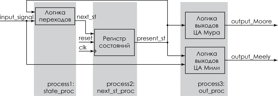
Figure 4 - Digital automatic with three processes
Such a variant of the description of the digital automaton allows the developer to separate the logic of transitions from the logic of forming the output signals and to perform synchronous recording of the state of the automaton in the state storage register. And this, in turn, makes it easier to describe and debug a synchronous digital machine.
The program itself is a combination of the three processes described above.
Digital machine description using three processes
LIBRARY ieee; USE ieee.std_logic_1164.ALL; ENTITY traffic IS PORT(clk : IN std_logic; cnt : IN std_logic; reset : IN std_logic; output : OUT std_logic_vector(2 downto 0) ); END ENTITY; ARCHITECTURE rtl OF traffic IS TYPE state_type IS (Init, R, RG, G, GR); SIGNAL next_st, present_st: state_type; BEGIN state_proc: PROCESS (present_st, cnt) BEGIN CASE present_st IS WHEN Init => IF cnt = '1' THEN next_st <= R; ELSE next_st <= Init; END IF; WHEN R => if cnt = '1' THEN next_st <= RG; ELSE next_st <= R; END IF; WHEN RG => IF cnt = '1' THEN next_st <= G; ELSE next_st <= RG; END IF; WHEN G => IF cnt = '1' THEN NEXT_st <= GR; ELSE next_st <= G; END IF; WHEN GR => IF CNT = '1' THEN next_st <= R; ELSE next_st <= GR; END IF; WHEN OTHERS => next_st <= Init; END CASE; END PROCESS; next_st_proc: PROCESS (clk, reset) BEGIN IF reset = '1' THEN present_st <= Init; ELSIF (rising_edge(clk)) THEN present_st <= next_st; END IF; END PROCESS; out_proc: PROCESS (present_st) BEGIN CASE present_st IS WHEN Init => output <= "000"; WHEN R => output <= "100"; WHEN RG => output <= "010"; WHEN G => output <= "001"; WHEN GR => output <= "010"; END CASE; END PROCESS; END rtl; The resulting CA graph obtained when compiling in the Quartus II package is shown in Figure 5 (Tools menu - Netlist Viewers - State Machine Viewer).

Figure 5 - Digital automatic with three processes. Compilation result
The result of the synthesis of the program shown in the listing above is shown in Fig. 6 (Tools menu - Netlist Viewers - Technology Map Viewer). To facilitate understanding of the figure, I / O elements are designated as IO, triggers as FF, and logic elements - LE. As you can see, the synthesis will result in a circuit of 5 triggers for storing the states of the digital automaton (in the case of the One Hot coding method) and two logic elements for implementing the transition scheme and generating output signals.

Figure 6 - Digital automatic with three processes. Technology Map Viewer
Description using two processes (Fig. 6) assumes that the transition logic block and the state register are combined into one process, in which the future state value of the digital automaton is selected using the case statement . Since there is no need to separate the signals of the current and future states, these two signals are replaced by one, the state , in which the state of the digital automat is stored.
The listing below shows an example of a description of the AC with an asynchronous reset. As a result of the compilation, the same result will be obtained as in the previous case - Fig.7.
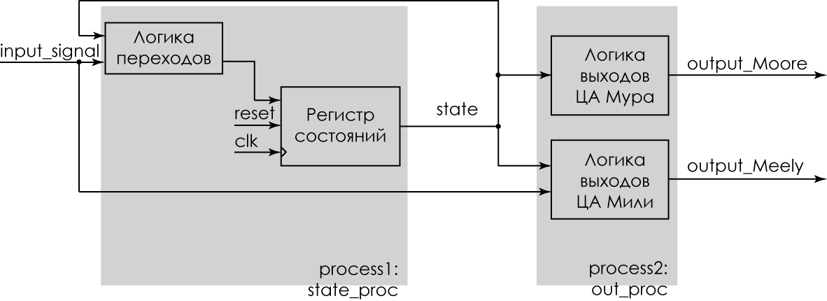
Figure 7 - Digital automatic with two processes
A description of the target center using two processes. Asynchronous reset
LIBRARY ieee; USE ieee.std_logic_1164.ALL; ENTITY traffic IS PORT(clk : IN std_logic; cnt : IN std_logic; reset : IN std_logic; output : OUT std_logic_vector(2 downto 0) ); END ENTITY; ARCHITECTURE rtl OF traffic IS TYPE state_type IS (Init, R, RG, G, GR); SIGNAL state: state_type; BEGIN state_proc: PROCESS (clk, reset) BEGIN IF reset = '1' THEN state <= Init; ELSIF (rising_edge(clk)) THEN CASE state IS WHEN Init => IF cnt = '1' THEN state <= R; ELSE state <= Init; END IF; WHEN R => IF cnt = '1' THEN state <= RG; ELSE state <= R; END IF; WHEN RG => IF cnt = '1' THEN state <= G; ELSE state <= RG; END IF; WHEN G => IF cnt = '1' THEN state <= GR; ELSE state <= G; END IF; WHEN GR => IF cnt = '1' THEN state <= R; ELSE state <= GR; END IF; END CASE; END IF; END PROCESS; out_proc: PROCESS (state) BEGIN CASE state IS WHEN Init => output <= "000"; WHEN R => output <= "100"; WHEN RG => output <= "010"; WHEN G => output <= "001"; WHEN GR => output <= "010"; END CASE; END PROCESS; END rtl; A digital automatic machine with synchronous reset , described by two processes is shown below. The synthesis results from the Technology Map Viewer are shown in Fig. 8, from which it can be seen that the size of the combination part has significantly increased in comparison with the asynchronous reset machine.
A description of the target center using two processes. Synchronous reset
LIBRARY ieee; USE ieee.std_logic_1164.ALL; ENTITY traffic IS PORT(clk : IN std_logic; cnt : IN std_logic; reset : IN std_logic; output : OUT std_logic_vector(2 downto 0) ); END ENTITY; ARCHITECTURE rtl OF traffic IS TYPE state_type IS (Init, R, RG, G, GR); SIGNAL state: state_type; BEGIN state_proc: PROCESS (clk) BEGIN IF (rising_edge(clk)) THEN IF reset = '1' THEN state <= Init; ELSE CASE state IS WHEN Init => IF cnt = '1' THEN state <= R; ELSE state <= Init; END IF; WHEN R => IF cnt = '1' THEN state <= RG; ELSE state <= R; END IF; WHEN RG => IF cnt = '1' THEN state <= G; ELSE state <= RG; END IF; WHEN G => IF cnt = '1' THEN state <= GR; ELSE state <= G; END IF; WHEN GR => IF CNT = '1' THEN state <= R; ELSE state <= GR; END IF; END CASE; END IF; END IF; END PROCESS; out_proc: PROCESS (state) BEGIN CASE state is WHEN Init => output <= "000"; WHEN R => output <= "100"; WHEN RG => output <= "010"; WHEN G => output <= "001"; WHEN GR => output <= "010"; END CASE; END PROCESS; END rtl; 
Figure 8 - The result of the synthesis of a digital machine with a synchronous reset
The description of a digital automaton using one process assumes that all logic is in one process. Some authors [5] believe that using one process to describe a digital automaton is simpler and allows you to more easily describe and debug a digital automaton. This statement is true for small digital machines. Increasing the number of states and using one process worsens the readability of the code. Because even the ancient Romans in the description of digital machines used the rule "Divide and rule."
Another argument, which is given in favor of using one process when describing a digital automaton, is that this variant implies the use of synchronous output signals. This condition is not mandatory for all CA and can be easily achieved, as was shown above when discussing the logic of the formation of output signals.
And yet, to complete the image, we give an example of a description of a digital automaton with asynchronous reset using a single process.
Description of CA in one process
LIBRARY IEEE; USE ieee.std_logic_1164.ALL; ENTITY traffic IS PORT(clk : IN std_logic; cnt : IN std_logic; reset : IN std_logic; output : OUT std_logic_vector(2 downto 0) ); END ENTITY; ARCHITECTURE rtl OF traffic IS TYPE state_type IS (Init, R, RG, G, GR); SIGNAL state: state_type; BEGIN PROCESS (clk, reset) BEGIN IF reset = '1' THEN state <= Init; ELSIF (rising_edge(clk)) THEN CASE state IS WHEN Init => IF cnt = '1' THEN state <= R; ELSE state <= Init; END IF; output <= "000"; WHEN R => IF cnt = '1' THEN state <= RG; ELSE state <= R; END IF; output <= "100"; WHEN RG => IF cnt = '1' THEN state <= G; ELSE state <= RG; END IF; output <= "010"; WHEN G => IF cnt = '1' THEN state <= GR; ELSE state <= G; END IF; output <= "001"; WHEN GR => IF cnt = '1' THEN state <= R; ELSE state <= GR; END IF; OUTPUT <= "010"; END CASE; END IF; END PROCESS; END rtl; The result of the program compilation is shown in Figure \ ref {FSM_1process_TMView}. Obviously, the result was the same as in the description using two processes with the only difference - the triggers for the output register were added.
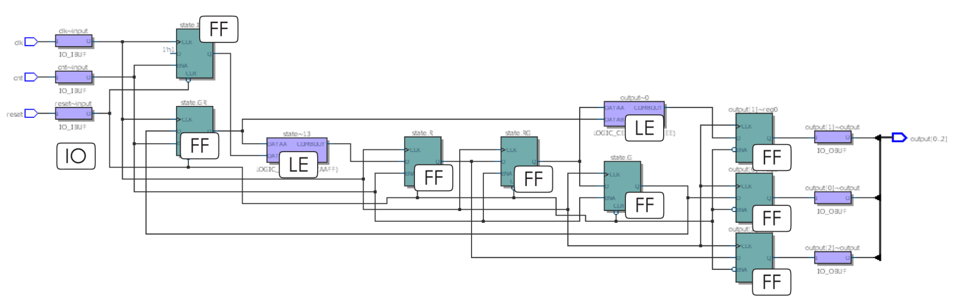
Figure 9 - Digital process with one process
Let's summarize the small results of our research.
The first and most important. Digital automatic exists! We saw him in the picture 5.
The second. Descriptions using two and three processes give the same result and the choice of description method depends on the preferences of the developer.
Third. You need to be very careful about the initial reset of the machine and the description of unused states.
Fourth. Description using a single process leads to the emergence of registers for the output signals of a digital automaton.
Bibliography.
1. Altera. Quartus II Handbook Version 10.0 Volume 1: Design and Synthesis Vol. 1, 2010 - 1820 p.
2. B. Cohen. VHDL Coding style and Metodologies. Kluwer Academic Publishers.2002 - 454 p.
3. DL Perry. VHDL programming by example. New York: McGraw-Hill, 2002.- 476 p.
4. DJ Smith. HDL chip design: ASICs and FPGAs using VHDL or Verilog. Madison, AL: Doone Publications, 1996. - 448 p.
5. A. Taylor. How to Implement State Machines in Your FPGA. Xcell, 81 (4), p. 52–57.
6. Xilinx. VHDL Reference Guide. XST User Guide.
7. K. G. Samofalov. The applied theory of digital automata. M .: 1987. 375 p.
PS PDF-version is here .
Source: https://habr.com/ru/post/254885/
All Articles