Reactive programming in the tabular processor
Spreadsheet processor (it’s about MS Excel or LibreOffice Calc) is a rather entertaining and versatile tool. I often (and have to) use its wide capabilities: automated reports, hypothesis testing, algorithm prototyping. For example, I used it to solve the tasks of the Euler project , a quick check of algorithms, implemented a parser of a single application protocol (I had to work). I like the visibility that can be achieved in a tabular processor, and I also like the non-standard use of everything that is possible. On Habré already appeared interesting articles on the topic of non-standard use of Excel:
"Assembler in 30 lines on Excel"
What to do an IT specialist in the army or how I wrote games on a VBA
“RPG game in Excel workbook”
In this long article I want to share my experiments in reactive programming with the help of tabular processor formulas. As a result of these experiments, I got a “computer” with a processor, memory, stack and display, implemented inside LibreOffice Calc using only formulas (except for the clock generator), which can be programmed in a certain assembly language. Then, as an example and proof-of-concept, I wrote the game "Snake" and the
Foreword
It all started with the fact that I became interested in various programming paradigms, attended an introductory lesson on Verilog in the robotics club; and here in the wikipedia article on the reactive paradigm I came across the following text:
Modern table processors are an example of reactive programming. Table cells can contain string values or a formula of the form “= B1 + C1”, the value of which will be calculated based on the values of the corresponding cells. When the value of one of the dependent cells is changed, the value of this cell will be automatically updated.
Indeed, anyone who used formulas in Excel knows that by changing one cell, we change the cells associated with it — it turns out to be rather similar to the propagation of a signal in a circuit. All these factors led me to the following thoughts: what if this “chain” would be quite complicated? Are formulas in the Turing tabular processor complete ? Is it possible to “program” formulas so that to get some non-trivial results? (for example make tetris) the last time I use Ubuntu at work and at home, I conducted all the experiments in LibreOffice Calc 4.2.7.2
')
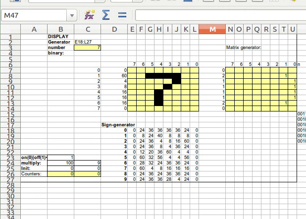
8x8 digital display
I started the experiments with the implementation of the display. The display is a set of 8x8 square cells. Here conditional formatting came in handy (it is in both Excel and Calc). Select the cells, go to Format / Conditional Formatting / Condition ... and customize the appearance: a black background, provided that the cell contains, for example, a space. Now if you write a space in the cell, it becomes black. Thus, the pixels of our display are realized. But this display you want to somehow manage. To my left, I selected a special column in which the numbers will be entered - the idea is that with this number we set the bit mask for display on the screen. At the top of the screen I numbered the columns. Now in each cell of the display we have to write a formula that will result in either a space or an empty string, depending on whether the required bit is set in the leftmost column.
= IF (MOD (TRUNC (<bitmask> / (2 ^ <display column number>)); 2); ""; "")
Here, in fact, there is a shift to the right (division by a power of two and then rejection of the fractional part), and then the 0th bit is taken, that is, the remainder of the division by 2, and if it is set, then a space is returned, otherwise the empty string.
Now, when writing to the leftmost column of a number, pixels are displayed on the display. Then I wanted to generate bit masks, for example, for decimal digits and, depending on the digit, fill the column of the display masks with the necessary numbers.
For the generation, another 8x8 construction was created, in which the units are put into the hands, and the formula turns it all into one number:
= SUMPRODUCT (<row of cells with ones and zeros>; 2 ^ <row with position numbers>)
As a result, I received such a matrix of bit masks for numbers:
Sign generator
Here each line corresponds to a decimal digit. Perhaps not the most beautiful figures came out, besides, the top and bottom rows are not used, well, as I drew, I drew it)
 0 0 24 36 36 36 36 24 0
 1 0 8 24 40 8 8 8 0
 2 0 24 36 4 8 16 60 0
 3 0 24 36 8 4 36 24 0
 4 0 12 20 36 60 4 4 0
 5 0 60 32 56 4 4 56 0
 6 0 28 32 24 36 36 24 0
 7 0 60 4 8 16 16 16 0
 8 0 24 36 24 36 36 24 0
 9 0 24 36 36 28 4 24 0
Here each line corresponds to a decimal digit. Perhaps not the most beautiful figures came out, besides, the top and bottom rows are not used, well, as I drew, I drew it)
Next, we apply the INDEX function, if we specify the matrix, row and column to it, then it returns the value from this matrix. So, in each cell of the display bitmask we write the formula
INDEX (<matrix>; <digit> + 1; <display line number> +1)
units are added because INDEX counts the coordinates from one, not from zero.
Cyclical links
Well, the display is ready, you write a number with your hands - it is displayed. Next, I wanted to make the figure switch itself, that is, a counter that would accumulate the amount. Here we had to remember about cyclic references in formulas. By default, they are turned off, we go into the options, we enable circular links, I have set up myself like this:
Calculation options
A cyclic reference implies a formula in a cell that depends on it itself, for example, in cell A1 we write the formula "= A1 + 1". Such a cell, of course, cannot be calculated - when the number of permissible iterations ends, Calc gives out either #VALUE or error 523. Unfortunately, Calc did not succeed in deceiving, the idea was to make one cell constantly growing to some limit. For example, in A1 I would write something like: = IF (A1 <500; A1 + 1; 0), and in B1, for example, like this: = IF (A1 = 500; B1 + 1; B1). 500 is simply a magic number that should provide a delay, that is, as long as the amount accumulates in A1, it would take some time and then B1 would change. (Well, I would have to take care of the initial initialization of the cells.) However, my plan did not work: Calc implemented some clever caching and verification algorithms (I even looked at the source code a little, but didn’t pick at all) to loop the calculation of the formula It does not work, no matter how clever dependencies are. By the way, in Excel 2003, this trick seemed to work partially, and, in general, there seems to be another model for calculating formulas, but I still decided to experiment in Calc. After that, I decided to make a counter on macros, and already hang all my dependencies on it. One comrade, in general, prompted me to make only a sync pulse (clock signal) on the macros, and I’m already hung on it with the counters and everything needed. I liked the idea - the macro was trivial: a delay and a change of state to the opposite. The counter itself consists of 4 cells:
Counter 0 to 9
| A | B | |
|---|---|---|
| one | Reset | 0 |
| 2 | Clock | [changed by macro 0 or 1] |
| 3 | Old value | = IF (B1 = 1; 0; IF (B2 = 0; B4; B3)) |
| four | New value | = IF (B1 = 1; 0; IF (AND (B2 = 1; B4 = B3); IF (B4 <9; SUM (B4; 1); 0); B4)) |
There is already a reset for initialization of the initial values, by entering 1 into A1.
This counter is connected to the display from the previous section, and it turns out what is seen in this video:
Counter + display 8x8
It is a pity that it did not work out completely without macros and the clock generator could not be done on the formulas. In addition, another problem arose: when the macro is looped - it blocks the main thread, and nothing can be done, you have to exit Calc. But I already had thoughts about interactivity, I wanted to somehow manage my future scheme, for example, to reset everything to zero, or to change some modes during operation.
Non-blocking timer
To my luck, it turned out that in Calc you can make it so that the main thread of the macro is not blocked. Here I was a little goof and just “googled” the ready solution, adapting it for myself. This solution required a bean shell for libreoffice. The package is called libreoffice-script-provider-bsh. The code consists of 2 parts: one on BeanShell, the other on LibreOffice Basic. Honestly, I didn’t understand the whole code ... I repent (I don’t own Java, BeanShell, and the LibreOffice object model is not particularly familiar), but I did correct something.
BeanShell part
 import com.sun.star.uno.Type;
 import com.sun.star.uno.UnoRuntime;
 import com.sun.star.lib.uno.helper.PropertySet;
 import com.sun.star.lib.uno.helper.WeakBase;
 import com.sun.star.task.XJobExecutor;
 import com.sun.star.lang.XInitialization;
 import com.sun.star.beans.PropertyValue;
 import com.sun.star.beans.XPropertyChangeListener;
 import com.sun.star.beans.PropertyChangeEvent;
 import com.sun.star.lang.EventObject;
 import com.sun.star.uno.AnyConverter;
 import com.sun.star.xml.crypto.sax.XElementStackKeeper;  // defines a start and a stop routine

 // This is a second time.
 xClassLoader = java.lang.ClassLoader.getSystemClassLoader ();

 try {
   xClassLoader.loadClass ("ms777Timer_01");
   } catch (ClassNotFoundException e)
   {
   System.out.println ("class not found - compiling");


 public class ms777Timer_01 extends PropertySet implements XElementStackKeeper
   {

 // These properties are the properties of the property.
   public boolean bFixedRate = true;
   public boolean bIsRunning = false;
   public int lPeriodInMilliSec = 2000;
   public int lDelayInMilliSec = 0;
   public int lCurrentValue = 0;
   public XJobExecutor xJob = null;

 // These are some additional properties
   Task xTask = null;
   Timer xTimer = null;

   public ms777Timer_01 () {
     registerProperty ("bFixedRate", (short) 0);
     registerProperty ("bIsRunning", (short) com.sun.star.beans.PropertyAttribute.READONLY);
     registerProperty ("lPeriodInMilliSec", (short) 0);
     registerProperty ("lDelayInMilliSec", (short) 0);
     registerProperty ("lCurrentValue", (short) 0);
     registerProperty ("xJob", (short) com.sun.star.beans.PropertyAttribute.MAYBEVOID);
     xTimer = new Timer ();
     }

 // XElementStackKeeper
   public void start () {
     stop ();
     if (xJob == null) {return;}
     xTask = new Task ();
     lCurrentValue = 1;
     bIsRunning = true;
     if (bFixedRate) {
       xTimer.scheduleAtFixedRate (xTask, (long) lDelayInMilliSec, (long) lPeriodInMilliSec);
       } else {
       xTimer.schedule (xTask, (long) lDelayInMilliSec, (long) lPeriodInMilliSec);
       }
     }

   public void stop () {
     lCurrentValue = 0;
     bIsRunning = false;
     if (xTask! = null) {xTask.cancel ();}
     }

   public void retrieve (com.sun.star.xml.sax.XDocumentHandler h, boolean b) {}

   class Task extends TimerTask {
     public void run () {// this function is called by a timer and the trigger is pulled, to which we pass either 0 or 1
         xJob.trigger (lCurrentValue.toString ());
          if (lCurrentValue == 0)
               lCurrentValue = 1;
         else
               lCurrentValue = 0;
       }
     }
   }

 System.out.println ("ms777PropertySet generated");
 } // of if (xClass = null)

 Object TA = new ms777Timer_01 ();
 return TA;
LibreOffice Basic part
 Sub clock // this function I hung up on the button to start and stop the "clock generator"
	 if isEmpty (oP) then // if started the first time, then create these unknown objects in which I did not understand
		 oP = GenerateTimerPropertySet ()
		 oJob1 = createUnoListener ("JOB1_", "com.sun.star.task.XJobExecutor")
		 oP.xJob = oJob1
		 oP.lPeriodInMilliSec = 150 // here is the delay
	 endif

	 if state = 0 then // and here the state change, 0 means the sync pulse is stopped and it needs to be started
		 oP.start ()
		 state = 1
	 else // otherwise means that the clock pulse has been started and must be stopped.
		 oP.stop ()
		 state = 0
	 endif
 End sub

 function GenerateTimerPropertySet () as Any // function in which the BeanShell script comes in
	 oSP = ThisComponent.getScriptProvider ("")
	 oScript = oSP.getScript ("vnd.sun.star.script: timer.timer.bsh? language = BeanShell & location = document")
	 GenerateTimerPropertySet = oScript.invoke (Array (), Array (), Array ()
 end function

 sub JOB1_trigger (s as String) // this is a trigger that is called on a timer from the BeanShell script
	 SetCell (1, 2, s)
 end sub

 sub SetCell (x as Integer, y as Integer, val as Integer) // set the value in the cell with coordinates X, Y
	 ThisComponent.sheets.getByIndex (1) .getCellByPosition (x, y) .Value = val
 end sub
So, on the sheet, I added a component button, called it “Start / Stop” and hung the clock function on it. Now, when the button was pressed, the cell changed its value to 0 or 1 at a specified interval, and the application flow was no longer blocked. It was possible to continue the experiments: hang some formulas on the sync signal and in every possible way “pervert”.
Then I began to think of something to do this. There is a screen, logic, sort of like, any can be implemented, there is a clock pulse. And what if you make a running line, or, in general, "Tetris"? Well this is what I get, practically, digital circuitry! Then I remembered an interesting game on digital circuitry: kohctpyktop , there one of the tasks was to make an adder and memory with address access. If there it was possible to do it, then it is possible here too - I thought. And if there is a screen, then you have to make a game. And where there is one game, there is another, then it is necessary to make it possible to make different games ... Approximately, somehow, it occurred to my idea to make a processor so that I could enter commands into cells, and he would read them, change his state and displayed what I needed.
There were a lot of thinking, trial and error, too, there were thoughts to make an emulator of a ready-made processor, for example Z80 and other equally crazy thoughts ... In the end I decided to try memory, stack, registers and a couple of commands like mov, jmp, mathematical commands like add , mul, sub, etc. it was decided not to do it, because Calc formulas already can do this and even more, so I decided to use directly the formulas of a tabular processor in my “assembler”.
Memory
Memory is such a black box to which you can send an address, a value, and a write signal to the input. If the recording signal is set, the value is saved at this address inside the black box. If the signal is not set, then the value stored earlier at this address appears at the output of the black box. Still need a separate entrance to clear the contents. This is the definition of memory I thought up for implementation. So, we have cells for storing values, and there are “interfaces”: inputs and output:
 m_address - address
 m_value_in - value to write
 m_set - write signal
 m_value_out - reading value, output signal
 m_clear - signal to clear
To make it more convenient, it's time to take the opportunity to call cells in Calc. Let's get to the cell, Insert / Names / Define ... This will give us clear names for the cells and use these names in the formulas already. So, I gave the names of 5 cells, as described above. Then I selected a square area of 10x10 - these are the cells that will store the values. Along the edges numbered rows and columns - to use the numbers of columns and rows in the formulas. Now each cell storing a value is filled with the same formula:
= IF (m_clear = 1; 0; IF (AND (m_address = ([cell_with_number_codes] * 10) + [cell_with__column_number]; m_set = 1); m_value; [current_cell])),
The logic here is simple: first the cleaning signal is checked, if it is set, then the cell is zeroed, otherwise we check whether the address matches (the cells are addressed with the number 0..99, the columns and rows are numbered from 0 to 9) and the signal is set to write if yes, then we take the value to write, if not, then we save our current value. We stretch the formula for all memory cells, and now we can add any values to memory. In the cell m_value_out, enter the following formula: = INDIRECT (ADDRESS (ROW ([first_cell_space]) + m_address / 10; COLUMN ([first_cell_space_setting]) + MOD (m_address; 10); 1; 0); 0), the function INDIRECT returns the value the link specified in the string, and the ADDRESS function just returns a string with a link, the arguments are a row and a column of a sheet, and a type of link. I designed it this way:

Here the yellow color indicates the input signals to which values can be written, there are no formulas in them, and what cannot be touched in red, the green field is the output value, it contains the formula and can be referenced in other formulas.
Stek
The memory is ready, now I decided to implement the stack. A stack is such a black box to which you can supply a value, a write signal and a read signal to the input. If a write signal is given, the stack keeps the value inside, next to the previously saved ones, if the read signal is given, the output stack gives the last stored value, and deletes it inside, so that the previous saved value becomes . We have already had to tinker here, because, unlike memory, the stack has an internal structure: a pointer to the top of the stack, which must correctly change its state. So, for the interface part, I got the following cells:
 s_address - the address from where the storage cells start, for example "Z2"
 s_pushvalue - the value to be written to the stack
 s_push - write signal
 s_pop - the signal to extract from the stack
 s_popvalue - output signal - value extracted from the stack
 s_reset - reset signal
For internal structures, I started the following cells:
sp_address - address of the cell where the stack pointer indicates sp_row - sp_address row sp_column - sp_address column sp - stack pointer, a number, for example 20 means that 20 values have already been saved to the stack and the next will be the 21st oldsp - old stack pointer, needed for sp to work correctly
Well, there remained a long row of cells in which values will be stored. Let's start with the formula for extracting the value of s_popvalue = IF (s_pop = 1; INDIRECT (sp_address; 0); s_popvalue), everything is simple, if the signal for extraction is given, simply take the value of the cell to the address where the stack pointer is displayed, otherwise save the old one value. Formulas for internal structures:
| cell | formula |
|---|---|
| sp_address | = ADDRESS (sp_row; sp_column; 1; 0) |
| sp_row | = ROW (INDIRECT (s_address)) |
| sp_column | = COLUMN (INDIRECT (s_address)) + sp |
| oldsp | = IF (AND (s_push = 0; s_pop = 0); sp; oldsp) |
It is easy to notice here that in order to form the address to which the stack shows, we take the address of the beginning of the stack and add the stack pointer to it. The old value of the stack pointer is updated in the case when both signals, both on the record and on the extract, are zero. So far, everything is simple. The formula for sp is quite complex, so I will give it with indents, for a better understanding:
Sp stack pointer
 = IF (s_reset = 1; // if the reset signal, then
     0;  // reset pointer to 0
     IF (AND (sp = oldsp; c_clock = 1); // otherwise we check if the stekpointer is equal to the old value and the clock signal is on (i.e., whether it is necessary to update the stekpointer)
         SUM (sp; IF (s_push = 1; // if a stackpoint update is required, then we add an offset to the old value (-1, 0 or 1)
                     one;  // add to the stackpoint 1, in case the push signal
                     IF (s_pop = 1; // otherwise, if the signal is pop, then add either 0 or -1
                         IF (sp> 0; -1; 0);  // -1 we add in the case when sp> 0, otherwise we add 0, that is, we leave the old value
                         0)));  // leave the old value in the case when neither push nor pop is cocked
         sp)) // if the stackpointer is not equal to the old value, or the clock signal is not entered, then we save the old value
5 nested IFs look monstrous, later on I would divide such long formulas into several cells so that each cell would have no more than 2 IFs.
It remains to give the formula for the cells that store the value:
= IF (s_reset = 1; 0; IF (AND (s_push = 1; ROW ([current_cell]) = sp_row; SUM (COLUMN ([current_cell]); 1) = sp_column; oldsp <sp); s_pushvalue; [current_cell ]))here, in principle, you can “parse” without indents, the essence is that some condition is checked and in the case when this condition is fulfilled, s_pushvalue is entered into the cell. The condition is as follows: the s_push signal must be cocked; cell row must match the row where sp points to; the column where sp is shown should be 1 greater than the column of our cell; well, sp should not be equal to its old value oldsp.
Picture for clarity, that I got:

CPU
Well, there is memory, there is a stack. I made the screen more than 8x8, because originally thought about Tetris, I did 10x20, as on BrickGame from the 90s. I used the first 20 cells of my memory as video memory, that is, I connected them to 20 lines of the screen (so they are dark red in the picture), now I can draw something on the screen by storing the values I need . It remains to implement the main thing: that will use the memory stack, read commands and execute them.
So, my CPU consists of the following parts:
CPU structures
 Inputs:
   c_reset - reset signal (resets the processor state)
   c_main - the address of the beginning of the program, the entry point
   c_clock - clock pulse, supplied from outside
   pop_value - value from the stack, connects to the stack = s_popvalue

 Internal structures:
   command - command to execute
   opA - first operand command
   opB is the second operand of the command
   cur_col - current row (where ip shows)
   cur_row - current column
   ip - instruction pointer, pointer to command
   oldip - old ip, needed for ip to work correctly
   ax - general purpose register (RON)
   bx - RON
   cx - RON
   rax - a copy of ax, needed to correctly modify the value of ax
   rbx - copy bx
   rcx - copy cx

 Outputs:
   mem_addr - memory address, connected to memory
   mem_value - value to write to memory or read from memory
   mem_set - signal to write to memory, connected to memory

   pop_value - value from the stack, or for writing to the stack, connected to the stack
   push_c - signal writing to the stack
   pop_c - read signal from the stack
In short, how everything works: the inputs are connected to the clock generator and reset (which I hung on the button for convenience, pure formality), the entry point is manually configured. Outputs are connected to the memory and stack, and depending on the commands, the necessary signals will appear on them. The command and operands are populated, depending on where the ip instruction pointer points to. Registers change their value, depending on the commands, and operands. ip can also change its value, depending on the command, but by default it simply increases by 1 at each step, and everything starts from the entry point that the person specifies. So the program can be located in an arbitrary place on the sheet, the main thing is to specify the address of the first cell in c_main.
The list of commands supported by the processor:
 mov - put the value in the register, the first operand is the name of the register, the second is the value, for example mov ax 666
 movm - put the value by address in memory, the first operand is the address in memory, the second operand is the value
 jmp - transition, one operand - a new ip value, the second operand is missing (but there must be something in the cell anyway! Calc magic, which I did not guess ...)
 push - get the value from the stack and put in the general-purpose register, the only operand is the name of the register (ax, bx or cx), the magic with the second operator is the same
 pop - put the value on the stack, operand - value
 mmov - get value from memory and put in register, first operand - memory address, second operand - register name
As operands and instructions, you can specify a formula in the program, the main thing is that in the cell, as a result, a value is obtained, namely, the values will be processed by the processor.
Let's start with simple internal structures: cur_col = COLUMN (INDIRECT (ip)) and cur_row = ROW (INDIRECT (ip)) are just the current row and the current column. command = IFERROR (INDIRECT (ADDRESS (ROW (INDIRECT (ip)); COLUMN (INDIRECT (ip)); 1; 0); 0); null) here you can see the difference between theory and practice. First, I had to insert error checking. Secondly, in the formula it was necessary to abandon the previous values of cur_col and cur_row - this led to some tricky cyclic dependencies and did not allow ip to work correctly, but we are talking about ip below. Thirdly, here I have applied the special value null (in case of an error), a separate cell with "-1" is selected for it.
The values of the operands are formed from the current row and column with offset:
 opA = IFERROR (INDIRECT (ADDRESS (cur_row; cur_col + 1; 1; 0); 0); null)
 opB = IFERROR (INDIRECT (ADDRESS (cur_row; cur_col + 2; 1; 0); 0); null)
Formula for instruction pointer:
In fact, this long formula is divided into several cells, but you can write everything in one.
opdip = IF (c_clock = 0; ip; oldip)
 ip = IF (c_reset = 1; // // reset check
     c_main;  // if there was a reset, then return to Maine
     IF (AND (c_clock = 1; ip = oldip); // otherwise we check whether the value should be updated (the clock is cocked and the old value is the same as the current one)
         IF (command = "jmp"; // if the value needs to be changed, then check if the command is passing by the transition
             opA;  // if the current jmp command, then take a new value from the operand
             ADDRESS (ROW (INDIRECT (ip)) + 1; // if the current command is not jmp, then just go to the next row
                     COLUMN (INDIRECT (ip))));
         ip)) // if the value is not necessary to update, then leave the old
In fact, this long formula is divided into several cells, but you can write everything in one.
opdip = IF (c_clock = 0; ip; oldip)
Formulas for registers also check which team is current, but more teams are already taken into account, so the IF nesting level is completely unreadable. Here I will give an example of how I distributed long formulas in several cells:
, .
A1 , , ax, .
rax=IF(c_reset= 1; 0; IF(AND(rax<>ax; c_clock=0); ax; rax))
. bx cx .
| A | B | C | D | E | |
|---|---|---|---|---|---|
| one | =IF(c_reset = 1; 0; B1) | =IF (c_clock = 1; C1; ax) | = IF(c_clock=1; IF (opA = «ax»; D1; IF(opB = «ax»; E1; ax));ax) | =IF(AND(opA = «ax»;c_clock=1);IF (command = «pop»; pop_value; IF (command = «mov»; opB; ax)); ax) | = IF(AND(opB=«ax»;command = «mmov»); mem_value; ax) |
A1 , , ax, .
rax=IF(c_reset= 1; 0; IF(AND(rax<>ax; c_clock=0); ax; rax))
. bx cx .
— :
| push_value | =IFERROR(IF(command=«push»; opA; push_value);null) |
| push_c | =IF(command=«push»; c_clock; 0) |
| pop_c | =IF(AND(command=«pop»; c_clock = 1); 1; 0) |
| mem_addr | =IF(c_reset = 1; 0; IF(OR(command = «movm»; command = «mmov»); opA; mem_addr)) |
| mem_value | =IF(c_reset = 1; 0; IF(command = «movm»; opB; IF(command=«mmov»; m_value_out; mem_value))) |
| mem_set | =IF(c_reset = 1; 0; IF(command = «movm»; 1; 0)) |
These are signals for working with memory and stack. At first glance, the signals push_c and pop_c seem to be the same in essence, but the formulas in them are slightly different. I can only answer, that they are obtained by numerous trial and error. In the process of debugging all this design there were a lot of bugs, and they still remained, unfortunately the processor does not always work "like a clock." For some reason, I stopped at this option, it means “differently” something did not work. Now I can’t remember exactly what it is.
Picture of my processor:

Here you can also see the debug fields - not values are displayed in them, but formulas in the form of text.
Programming
So, the computer is ready, you can start writing the program. During the programming process, several problems were discovered, some of which were solved, some still remained:
- «»
- , , ,
- «» , , . , , : 150-200
«» «», , . , «» , ( , «») «» .
, .. , : 4 4 1, , key_up, key_down, key_left key_right. key_trigger=IF(key_up; «U»; IF(key_down; «D»; IF(key_left; «L»; IF(key_right; «R»; key_trigger)))), .
«Debug», , ( 1 0 clock). : . .
«» :
''
«» : ; ; , ; .
.
, ax BXBYHHTT, 4 : (BX BY), (HH), (TT). , .
HEAD //
TAIL //
BXBY = rand //
HXHY = *HEAD //
TXTY = *TAIL //

loop:
	read DIRECTION //   ()
	HEAD++ //
	HXHY += DIRECTION //
	[HEAD] = HXHY //
	BXBY <> HXHY ? JMP cltail //        ,    " "
	BXBY = rand //
	[BY] = OR([BY]; 9-2^BX) //     ( 20      1020)
	JMP svtail //
cltail:
	[TY] = AND([TY]; XOR(FFFF; (9-2^TX))) //
	TAIL++ //
	TXTY = [TAIL] //
svtail:
	[HY] = OR([HY]; 9-2^HX) //

	JMP loop //
.
, ax BXBYHHTT, 4 : (BX BY), (HH), (TT). , .
. :
Initialization
| Command | Operand 1 | Operand 2 | Comment |
| mov | ax | =RANDBETWEEN(0;9) * 1000000 + RANDBETWEEN(0;19)* 10000 + 2120 | BXBYHHTT |
| movm | 21 | 509 | Head: x — 5, y — 9 |
| movm | 20 | 409 | Tail: x — 4; y — 9 |
| mov | cx | R | direction init |
| mov | bx | 5090409 | HXHYTXTY |
| movm | =MOD(ROUNDDOWN(rax/10000);100) | =2^(9-ROUNDDOWN(rax/1000000)) | draw ball |
. Calc . :
loop:
	cx = IF(OR(AND(rcx="U";key_trigger="D");AND(rcx="D";key_trigger="U");AND(rcx="L";key_trigger="R");AND(rcx="R";key_trigger="L"));rcx;key_trigger)
	ax = IF(ROUND(MOD(rax;10000)/100) < 89; ROUND(MOD(rax;10000)/100)+1; 20) * 100 + MOD(rax;100) + ROUND(rax/10000) * 10000
	bx = IF(AND(rcx="U";MOD(ROUND(rbx/10000);100)>0);rbx-10000;IF(AND(rcx="D";MOD(ROUND(rbx/10000);100)<19);rbx+10000;IF(AND(rcx="R";ROUND(rbx/1000000)<9);rbx+1000000;IF(AND(rcx="L";ROUND(rbx/1000000)>0);rbx-1000000;"FAIL"))))
	push cx
	[ROUND(MOD(rax; 10000)/100)] = ROUND(rbx/10000)
	jmp IF(ROUND(rax/10000) <> ROUND(rbx/10000); ctail; next)
	ax = MOD(rax;10000) + MOD(MOD(ROUND(rax/10000);100)*11 + 3; 20) * 10000 + MOD(ROUND(rax/1000000)*3+2;10)*1000000 // ball generator
	cx = [MOD(ROUND(rax/10000);100)] // get [BY]
	[MOD(ROUND(rax/10000);100)] = BITOR(rcx; 2^(9-ROUND(rax/1000000))) // draw ball on scr
	jmp svtail
ctail:
	cx = [MOD(rbx;100)] // cx = [TY]
	[MOD(rbx;100)] = BITAND(rcx; BITXOR(HEX2DEC("FFFF"); 2^(9-ROUND(MOD(rbx;10000)/100)))) // clear tail on scr
	ax = IF(MOD(rax;100) < 89; rax + 1; ROUND(rax/100)*100 + 20)
	cx = [MOD(rax;100)] // cx = [TT]
	bx = ROUND(rbx/10000)*10000 + rcx
svtail:
	cx = [MOD(ROUND(rbx/10000);100)] // cx = [HY]
	[MOD(ROUND(rbx/10000);100)] = BITOR(rcx; 2^(9-ROUND(rbx/1000000))) // draw head on scr
	pop cx
	jmp loop
, ax 4 : BXBYHHTT, bx HXHYTXTY, , cx — , . , , , .
The next step was only to replace the assignments with the mov, movm, and mmov commands, respectively, and transfer the code to the cells on the sheet.
Of the interesting features worth noting random number generator. The function of the tabular processor does not suit us, because at each generation of the ball coordinates in the program, we need to have new random values. A function is calculated only once and then lies in the cell until you refresh the sheet. Therefore, a so-called pr. linear congruential method .
To simplify, checks that the ball appeared in the middle of the snake is not done. Also, no checks are made on the passage of the snake through itself.
The program works very "sloopochno." I recorded the video in real time and accelerated 16 times. At the end of the video, I pass through myself and crash into a wall (FAIL appears in the bx register and the snake no longer crawls anywhere).
16 times faster video:
Real time
In the video you can see that at the bottom of the sheet there is the code of another small program - the output of a
Video accelerated 16 times:
The project is available on a githab ; LIbreOffice Calc with BeanShell is required.
Source: https://habr.com/ru/post/254569/
All Articles