Optimization Planning with Unity
Unity contains a number of settings and tools to achieve smooth graphics in games. For this project, we selected those with which difficulties may arise, and analyzed their impact on the performance of games on Intel GP.
We are considering using Unity from the point of view of the game developer. We sought to find areas of performance degradation, and then determine how to improve application performance using built-in Unity tools. One of the advantages of Unity is the ability to quickly create content, but in order to achieve performance, especially on mobile devices and tablets, the developer will need to carefully plan the use of built-in performance optimization mechanisms. In this article, new and existing Unity users are offered tips on improving performance when creating levels and games, and also describes new ways to create content.
Introduction
Creating games using Unity is relatively easy. Unity has a store where you can purchase various items, such as models, ready-made scripts, demos, or even full games. For testing, I worked with an existing game to determine in which areas you can achieve improved performance, and in which not. I used a Unity technical demo called Boot Camp (it can be downloaded for free at the resource store) to assess the complexity of the problem.
')
I used Unity 3.0 to create game parameters and launch all scenes. Testing was conducted on a computer with an Intel Core 3rd generation processor with Intel HD Graphics 4000. The test results are not applicable to mobile devices.
Quality manager
In Unity, additional rendering options are available for games: Edit-> Project Settings-> Quality (Fig. 1). These are customizable rendering options that can be customized individually. Unity contains built-in documentation explaining quality parameters and their configuration using the Unity scripts API.

Figure 1. Access to tags and layers through the menu Edit-> Project Settings-> Tag inspector
To find out how to optimize in Unity, I decided to try changing the quality settings in order to understand what could be won or lost, although I did not test all the available parameters.
Texture quality
In the Quality Settings Inspector there is a drop-down menu where you can select rendering resolution for textures. You can choose resolution 1/8, 1/4, 1/2 or full resolution. To assess the gain or decline in performance with different texture resolutions, I measured the frame rate of the test scene with all the default quality settings available in Unity (Fastest, Fast, Good, etc.), changing only the quality of textures before each measurement.
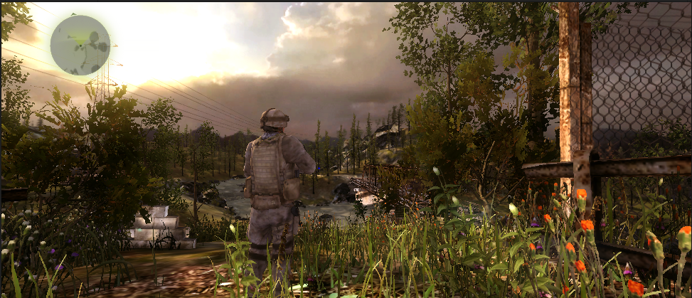
In fig. Figures 2 and 3 show a comparison between scenes with 1/8 resolution of textures and full resolution textures.
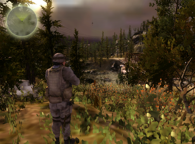
Figure 2. Unity * Boot Camp Scene with 1/8 resolution

Figure 3. Unity * Boot Camp Scene full resolution
We measured the frame rate (in frames per second) using Intel Graphics Performance Analyzers (Intel GPA) after changing the texture resolution. At the quality level of Fantastic (table 1), it can be seen that the performance has not changed very much with changing texture size.
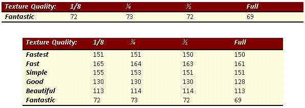
Table 1. Frame rate change when switching between different texture quality in Unity
On computers with Intel GPUs, performance theoretically does not change depending on the size of the textures, but other factors should be taken into account, such as the total amount of device memory and the use of memory by the application.
Shadow Distance
Shadow Distance is a parameter that determines the depth of rejection used for shadows of game objects. If a game object is within a specified distance from the camera, then the shadows of this object are drawn, if the object is farther than this distance, then the shadows of such an object are not displayed (excluded from the drawing).
Depending on the parameters used, shadows can adversely affect performance, since their calculation and rendering are resource-intensive operations. Testing the effect of the Shadow Distance parameter
- Create a test scene.
- Set the default Unity quality settings for this scene.
- Gradually increase the value of the Shadow Distance parameter and measure the frame rate using Intel GPA.
- Select another default quality value in Unity and repeat the frame rate measurement.
In this test, the Fastest and Fast quality levels were not used, since shadows are disabled in these modes.
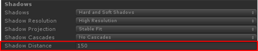
Figure 4. This parameter is available in the Inspector menu: Edit-> Project Settings-> Quality
Figure 5. Unity * Boot Camp technical demo
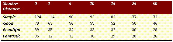
Table 2. Frame rate change when the Shadow Distance parameter value changes in the technical demonstration of Unity * Boot Camp
Shadows significantly affect performance. The test showed that the frame rate dropped by almost half when switching the distance from 0 to 50 in the Simple mode. It is important to consider whether game objects are visible and to make sure that unnecessary shadows are not drawn. Shadow rejection depth can be customized using Unity scripts for various situations. We only checked the effect of shadow rejection depth, but similar performance changes may occur when setting other parameters for shadow quality.
Layers
All game objects in Unity are assigned a layer when they are created. Initially, all objects are assigned a default layer, as shown in Fig. 6, but you can create your own unique layers. This can be done in two ways. You can simply click the Layer field and select Add New Layer. You can also use the menu Edit-> Project Settings-> Tags.

Figure 6. The Layer menu in the Inspector game object
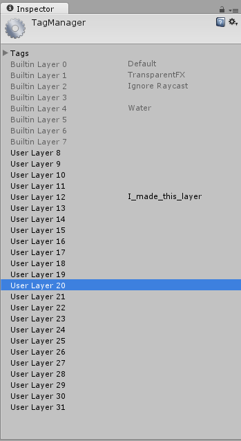
Figure 7. Tag Manager in the Inspector window
In the Inspector window (Fig. 7), you can create a new layer and specify which layer number it should belong to. Using both methods opens the same Tag Manager window. After creating a layer, you can assign game objects to this layer by selecting the desired layer in the parameters window in the Inspector window of the game object in the Layer field. In this way, you can group objects on the same layers in order to process them together. Remember what layers are and how to create and customize them when I talk about some of the other layer features in this article.
Layer rejection distances
The camera will not render game objects that are outside the clipping plane in Unity. Using Unity scripts, you can set a shorter distance to the clipping plane for certain layers.
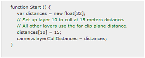
Figure 8. Sample Scenario from Unity Documentation with Changing Layer Rejection Distance
Setting a shorter cull distance for game objects requires some work. First you need to place the objects on the layer. Then you need to write a script to change the rejection distance of this particular layer, and assign the script to the camera. Sample script in fig. 8 shows how to create an array of 32 floating point values corresponding to the 32 available layers that can be created using the menu Edit-> Project Settings-> Tags. If you change the index value in this array and assign it to camera.layerCullDistances , then the rejection distance will change for the corresponding layer. If you do not assign a number to an index, the corresponding layer will use the far clipping plane of the camera.
To test the performance of layerCullDistances, I created three scenes filled with objects of low, medium and high complexity. In these scenes, identical game objects are grouped together and arranged in a row with a gradual distance from the camera. I used Intel GPA to measure the frame rate while gradually increasing the layer rejection distance, adding groups of objects for each measurement (i.e., one group of objects for the first measurement, 6 groups of objects for the sixth measurement).
Figures 9, 10, and 11 show scenes that I used for testing with objects of different types.
Boots: polygons - 278, peaks - 218
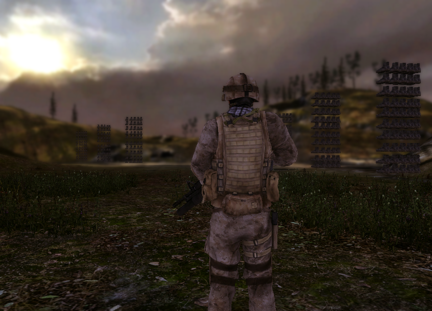
Figure 9. Test scene with boots — objects with a low number of polygons and vertices
Dinosaurs: polygons - 4398, peaks - 4400
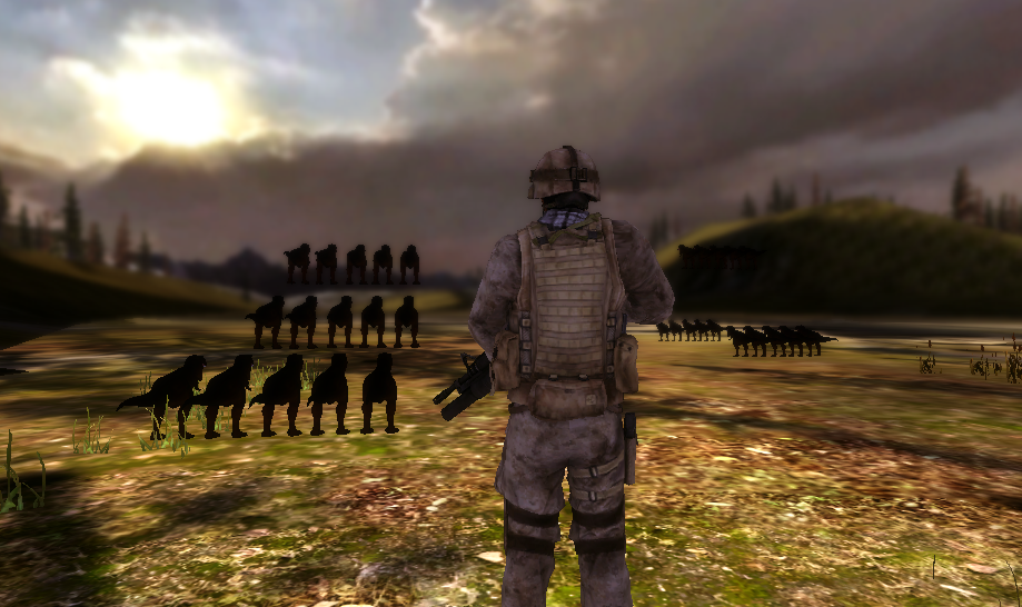
Figure 10. Test scene with dinosaurs - objects with an average number of polygons and vertices
Airplanes: polygons - 112 074, tops - 65 946

Figure 11. Test scene with airplanes - objects with a large number of polygons and vertices
Tables 3, 4 and 5 show the change in frame rate in all test scenes.
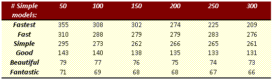
Table 3. Data obtained in the scene with boots (Fig. 9)
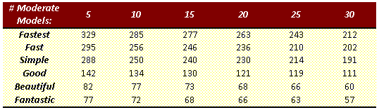
Table 4. Data obtained in the scene with dinosaurs (Fig. 10)
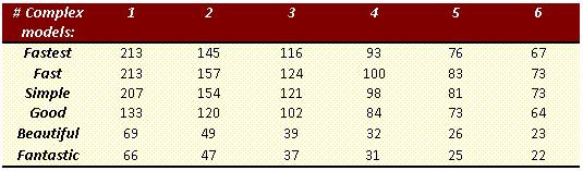
Table 5. Data obtained in the scene with the aircraft (Fig. 11)
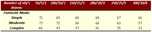
Table 6. Data from all test scenes in Fantastic mode
This data shows the performance gains that can be achieved with layerCullDistances in Unity.
Table 6 shows how performance changes as the number of objects on the screen increases, especially if they are complex objects. From the point of view of the game developer, the proper use of layerCullDistances can significantly improve performance. For example, for small objects with a complex model that are located farther from the camera, you can adjust the drawing only with a sufficient approximation, when these objects can already be distinguished. When planning and creating levels, the developer should take into account the complexity of the models and the visibility of objects located at a great distance from the camera. Advance planning allows you to achieve better results when using layerCullDistances .
Camera
I studied the possibilities of working with the camera in Unity and its settings. I tried to select various parameters, worked with other components and additions.
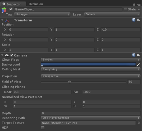
Figure 12. The Inspector menu that opens after selecting a camera.
When creating a new scene, by default, only one game camera object appears called Main Camera. To add another camera, first create an empty game object: Game Object-> Create Empty. Then select this empty object and add the camera component: Components-> Rendering-> Camera.
The cameras in Unity support extensive configuration options, as shown in Figure 2. 12. Here are the settings I considered: Rendering Path and HDR.
Render path
Using the Render Path parameter, you can specify in Unity how to handle the rendering of light and shadows in the game. Three types of rendering are supported in Unity, here they are in order from the most resource-intensive to the least resource-intensive: Deferred (delayed, only in Unity Pro), Forward (advanced) and Vertex Lit (vertex lighting). In each case, shadows and light are handled a little differently, and they require different amounts of CPU and GP resources to process them. It is important to understand for which platform and for which equipment is being developed to select the appropriate renderer. If you select a renderer that is not supported by the graphics adapter, Unity automatically switches to a less resource-intensive rendering method.
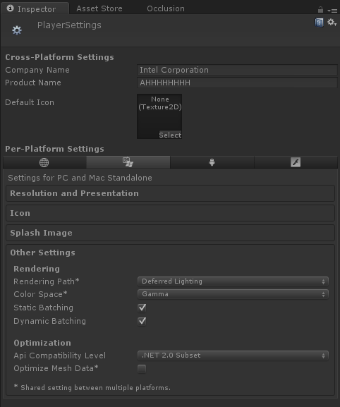
Figure 13. Player Settings Inspector window
You can adjust the Rendering Path in two ways. The first way:
Edit-> Project Settings-> Player (Fig. 13). The Rendering Path drop-down list is located on the Others Settings tab. The second way: using the Camera Inspector user interface (Fig. 14). If you select any option other than Use Player Settings, the default settings will be replaced, but only for this camera. Therefore, you can use different cameras with different render buffer settings for light and shadows.
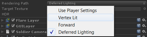
Figure 14. Drop-down list when selecting the Rendering Path option in the Camera window
Developers need to know how the various lighting rendering modes that make up Unity work. The reference section at the end of this document provides links to Unity documentation. Make sure that you know the target audience of your game and the platform on which potential users will play this game. This will help you choose the appropriate rendering method for this platform. For example, if a game contains several light sources and graphic effects that use deferred rendering, then on computers with a low-power graphics adapter, playing such a game would be simply impossible. If your target audience includes casual game lovers whose devices do not have high computing power, then problems may also arise. Developers need to know the target platform for which their game is intended, and appropriately choose how to render and handle the lighting in the game.
HDR (extended dynamic range)
In normal rendering, the values of red, green (G) and blue (B) colors of each pixel are represented by a decimal number whose value is from 0 to 1. If you limit the range of values for these colors, the lighting will look unrealistic. To achieve more natural lighting, you can enable High Dynamic Range (HDR) in Unity. In this case, the R, G, and B values of each pixel may fall outside the normal range. HDR creates an image buffer that supports values outside the range from 0 to 1, and performs post-processing of graphic effects, such as blur and glare. After calculating the post-processing effects, the R, G, and B values in the image buffer are reset to values within the range from 0 to 1 using Unity's shade map technology. If the construction of hue maps is not performed using HDR, then the pixels may be outside the acceptable range, due to which some colors of the scene may look wrong compared to others.
When using HDR, watch for parameters that affect performance. When using advanced scene rendering, HDR will work only with graphic effects. Otherwise, the inclusion of HDR will not affect anything. With deferred rendering, HDR is always used.
If the scene is processed using deferred rendering, and graphic effects are assigned to the camera, then HDR should be enabled. In fig. 15 compares the number of render calls for a scene with effects and deferred rendering with HDR turned on and off. Without HDR, the number of render calls is significantly higher than with HDR, if the scene contains effects. In fig. 15, the number of rendering calls is represented by individual blue stripes, and the height of each strip corresponds to the load of each call to the GP.

Figure 15. Measurement using Intel Graphics Performance Analyzers shows that when HDR is disabled, over 2000 render calls are performed, while HDR is on — just over 900 render calls
Check out Unity's HDR documentation to understand how this functionality works. You also need to know in which cases the extended dynamic range should be applied in order to get a performance boost due to this, and in which cases it does not make sense.
Graphic effects
Unity Pro contains a number of graphical effects that enhance the look of the scene. To add an Image Effects component after creating a project, use the Assets-> Import Package-> Image Effects menu. After importing, you can add an effect to the camera in two ways. Click the game object of the camera, in the camera window, select Add Component, and then Image Effects. You can also click the camera object in the menu by selecting Component-> Image Effect.
Broken Screen Shading - SSAO
Screened Shading in Screen Space (SSAO) is a graphic effect as part of the Image Effect package in Unity Pro. In fig. 16 shows the difference between enabled and disabled SSAO. Images look similar, but performance varies significantly. With a scene without SSAO, the frame rate was 32 frames per second, and with SSAO - 24 frames per second, that is, 25% lower.
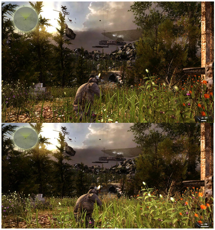
Figure 16. Comparison of the same level with disabled SSAO (top) and SSAO enabled (bottom)
Be careful when adding graphic effects, as they may adversely affect performance. In preparing this document, we tested only SSAO, but we should expect similar results when using other effects.
Exclusion of obstructed objects
The exclusion of obscured objects is the shutdown of rendering not only those objects that are located beyond the clipping plane of the camera, but also objects hidden behind other objects. This is very beneficial in terms of performance, since the amount of information that needs to be processed is significantly reduced. However, setting the exclusion of obscured objects is not too easy. Before setting up the scene to exclude obscured objects, you should understand the terminology used.
A defensive object — an object marked as a defensive object acts as a barrier: all objects blocked by it that are marked as blocked are not drawn.
Shielded object - if you mark an object in this way, it will not be rendered in Unity if it is blocked by a shielding object.
For example, if you mark all the objects inside the house as obscured, the house itself can be marked as obscuring. If the game character is located outside this house, then all objects inside the house that are marked as obscured will not be drawn. This speeds up processing on the CPU and GP.
The use and configuration of eliminating obscured objects is documented in Unity. Refer to the reference section for setup information.
To demonstrate the change in performance (depending on the exclusion of obscured objects), I created a scene where a wall is in the foreground, and behind it are objects with complex models. I measured the frame rate of the scene with the exception of obscured objects, and then without it. In fig. 17 shows a scene with a different frame rate.

Figure 17. In the image on the left, the exclusion of obstructed objects is disabled, all objects located behind the wall are drawn, so the frame rate is 31 frames per second. In the image on the right, the exclusion of obscured objects is turned on, objects obscured by the wall are not drawn, so the speed has increased to 126 frames per second.
Exclusion of obscured objects must be manually configured by developers. We should not forget about the exclusion of obscured objects when designing games, since this reduces equipment requirements and improves performance.
Level of Detail (LOD)
Using the level of detail (LOD), you can assign several models of different complexity to one game object and switch between them depending on the distance between the object and the camera. This can be beneficial in terms of performance for complex game objects that are far from the camera. Using the level of detail you can automatically simplify the model. For information on using and setting the level of detail, see the Unity documentation. The link is given in the reference section.
To test the performance gain when changing the level of detail, I created a scene with a group of houses, which were assigned 3 different models. Placing the camera in the same place, I measured the frame rate of the scene with the houses when using the most complex model. Then I changed the distance of detail to use models with a lower degree of detail, and took the measurement again. I have done this procedure for the three levels of models and recorded the data in table 5.
In fig. 18, 19, and 20 show three different levels of model complexity with the number of polygons and vertices in each model.
| Best quality - level of detail 0 | |
|---|---|
| Building A • Summits - 7065 • Polygons - 4999 Building B • Summits - 5530 • Polygons - 3694 |  Figure 18. The level of detail is 0. This is the highest the level of detail at which to use the most complex models (click to enlarge) |
| Medium quality - level of detail 1 | |
| Building A • Summits - 6797 • Polygons - 4503 Building B • Polygons - 5476 • Summits - 3690 |  Figure 19. Level of detail 1. This level is one step down the scale of detail on it Models of medium complexity are used (click to enlarge) |
| Low quality - level of detail 2 | |
| Building A • Summits - 474 • Polygons - 308 Building B • Polygons - 450 • Summits - 320 | 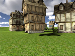 Figure 20. Level of Detail 2. This is the last level. details, here are used the least complex models (click to enlarge) |
Switching between different levels of detail, I measured the frame rate for comparison (Table 7).

Table 7. Comparison of frame rate at different levels of detail
Table 7 shows an increase in performance when setting up and using different levels of detail. Frame rate increases significantly when switching to less complex models. However, this increases the amount of work of artists who will have to create several models of each object. Game designers must decide for themselves whether they should spend extra time drawing additional models in order to increase their productivity.
Batch processing
Excessive number of rendering calls can lead to excessive load on the CPU and decrease in performance. The more objects on the screen, the more rendering calls need to be made. In Unity, so-called batch processing is supported, allowing you to put several game objects into a single render call. Static batch processing is designed for static objects, and dynamic - for moving objects. Dynamic batch processing is performed automatically when all requirements are met (see the batch processing documentation), and static batch processing must be set manually.
There are certain requirements for co-rendering objects for both dynamic and static batch processing. All of these requirements are listed in the batch processing document referenced in the reference section.
To test the performance gain in static batch processing, I created a scene with complex game objects in the form of airplanes (Fig. 21) and measured the frame rate with and without batch processing (Table 8).
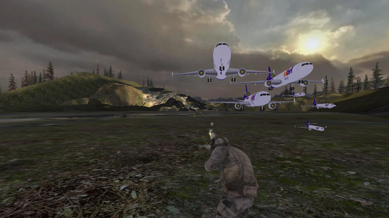
Figure 21. Static batch processing of a test scene with very complex aircraft models

Table 8. The difference in personnel rate and the number of rendering calls when the static batch processing is enabled and disabled (Fig. 21)
Unity supports two types of batch processing, dynamic and static. To get the most benefit from batch processing, try to combine as many objects as possible into a batch for one render call. For information on which objects are suitable for dynamic or static batch processing, see the Unity documentation.
Conclusion
In Unity, you can easily start working on projects, but with no less ease, you can prevent the lack of application performance. Unity supports a number of settings and tools that allow you to achieve smooth graphics in games, but not all of these tools are conveniently configured and intuitive. In addition, some settings in Unity, if enabled or incorrectly used, can adversely affect the performance of games. When developing with Unity, it is important to prepare a plan in advance, because for some performance related functions, manual tuning is required, which can be much more difficult if you do not plan it in advance (when creating a project).
Additional materials on the topic
Original article: How To Plan Optimizations with Unity *
Quality Parameter Documentation
Quality Parameter Script API
Technical demonstration Boot Camp
Level of detail documentation
Documentation on the exclusion of hidden parts
Batch Processing Documentation
Rendering Path Documentation
Intel GPA
Adding support for multitouch input to Unity * games for Microsoft Windows * 7 and classic Windows * 8 interface
Implementing gesture sequences in Unity * 3D using the TouchScript library
Using touch gestures to control physics parameters in Unity * 3D with TouchScript
Use standard GUI Unity * 3D in combination with TouchScript resources
Source: https://habr.com/ru/post/254353/
All Articles