Steel manipulator HEXAPOD
In the following presentation I would like to demonstrate the implementation of the six-pointed manipulator HEXAPOD, made of ship steel. The current project does not claim to originality, innovative approaches, the implementation of complex control algorithms, the use of mathematical models of behavior, as well as the initial design of existing and effectively working hardware. In the current article I will try to present my own approach to the implementation of the manipulator from the maximum available means and materials of the peripheral city.
The main bias at this stage was made in the direction of the hardware component and not very complex software. In the future it is planned to use BeagleBoard-xM, the organization of autonomous modes of operation and minimal processing of video data. Doing everything at the same time is physically not enough time. This is my first experience in robotics, so some aspects of the device have been thought out and adjusted already in the course of its implementation.
')
The prerequisite for creating a manipulator was the animated film Ghost in the shell, which became a cult film. Released almost two decades ago, this film made a lasting impression on many, and on me in particular. Years later, having acquired a certain level of technical knowledge, having time and a certain amount of available funds, I decided to implement a constructive from the field of robotics.
Initially, I’ll make a reservation that, in my personal view, the canonical concept of “robot” is inherently associated with autonomous work algorithms. Since this device cannot function (at the current software level) without human intervention, the definition of a “manipulator” will be used in the current article.
One of the open projects from grabcad.com was chosen as the initial construction. It was relatively long ago, before the general interest in such six-pointed devices. Therefore, the choice of existing open source projects at that time was not great, and it was very difficult to develop your first robotic design of this level from scratch. The project was modified in the direction of reducing the weight of the structure and simplifying the edge lines of the parts. Below is an isometric view of the manipulator in the software product SolidWorks (one of the penultimate versions of the modification; the latest one, after so many years, was never found):

As the material of the manipulator was originally planned to use aluminum. But to find such an opportunity within the framework of my peripheral city at that time did not work out (perhaps, years later, something changed in this area, however, I doubt it). The legacy of the past times came to the rescue - the remnants of shipboard carbon steel and the possibility of plasma cutting along it. In addition, the project from SolidWorks 2007 was suitable as the source data, which simplified preparation for manufacturing. Material thickness - 2mm. The manufacture of plexiglass or plastic construction was possible, but was not considered initially, since the desire to make a manipulator of metal prevailed over a common view on things. Some time later, the details were received (I apologize for the quality, some photos in the article were made by an old phone):

After an external inspection of the parts, everything was neatly folded in a box and sent to the "stage of removing residual metal tension." To put it mildly - postponed for a very long time, due to lack of free time.
After a while I returned to the manipulator, and began to think over the power supply system, communication devices, choose a servo drive and control electronics. Based on the desired approach to the implementation, it was assumed that the final weight would be very significant, so the servo needed to be chosen with some margin of effort. However, the cost also played a significant role. Based on the price / quality ratio, HK15328A servo drives were purchased, having a metal gearbox, double ball bearing, brass bushings, force 12.8 kg per cm, at a voltage of 6.0 V., weight 58 grams. The quality of workmanship is tolerable, although there are no dust pads, the control board dangles freely inside the case, the leads of the wires are not sealed, lubrication is almost absent in half of the ordered drives, there is little heating during continuous load. All of the above is offset by the cost of the drive ~ $ 7. 18 drives were ordered, all were reassembled, lubricated with graphite grease and tested under load. For a long time of operation, none of the add has failed. Below is a photo of the internal servo HK15328A:

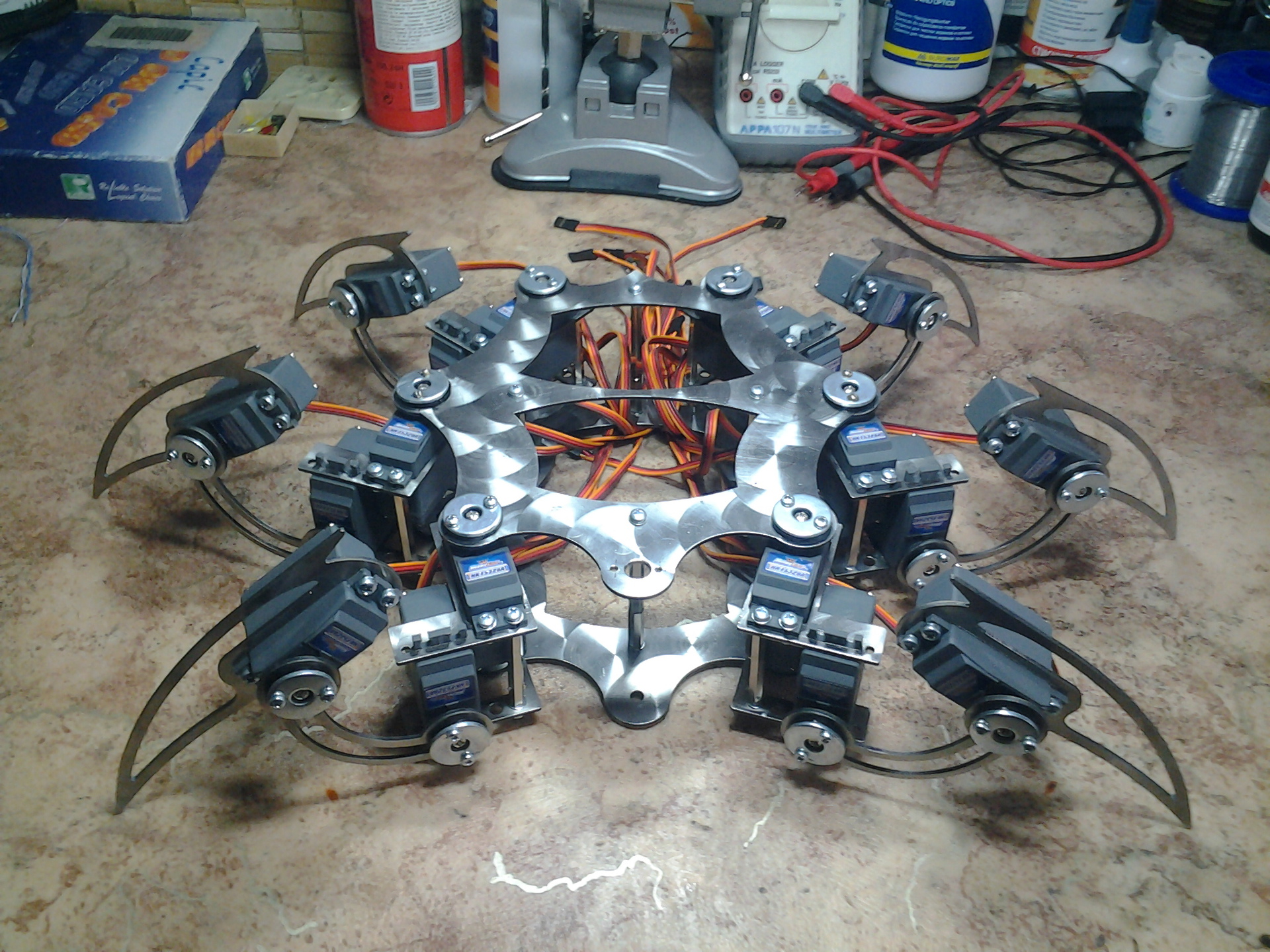
At the time of ordering aluminum rocking was not in the range. It was decided to use the plastic rocking, supplied with the drive, secured by suitable metal washers. After finishing with a file and grinding parts, working on a drilling machine, using taps and mounting servos, the manipulator frame acquired the following appearance:
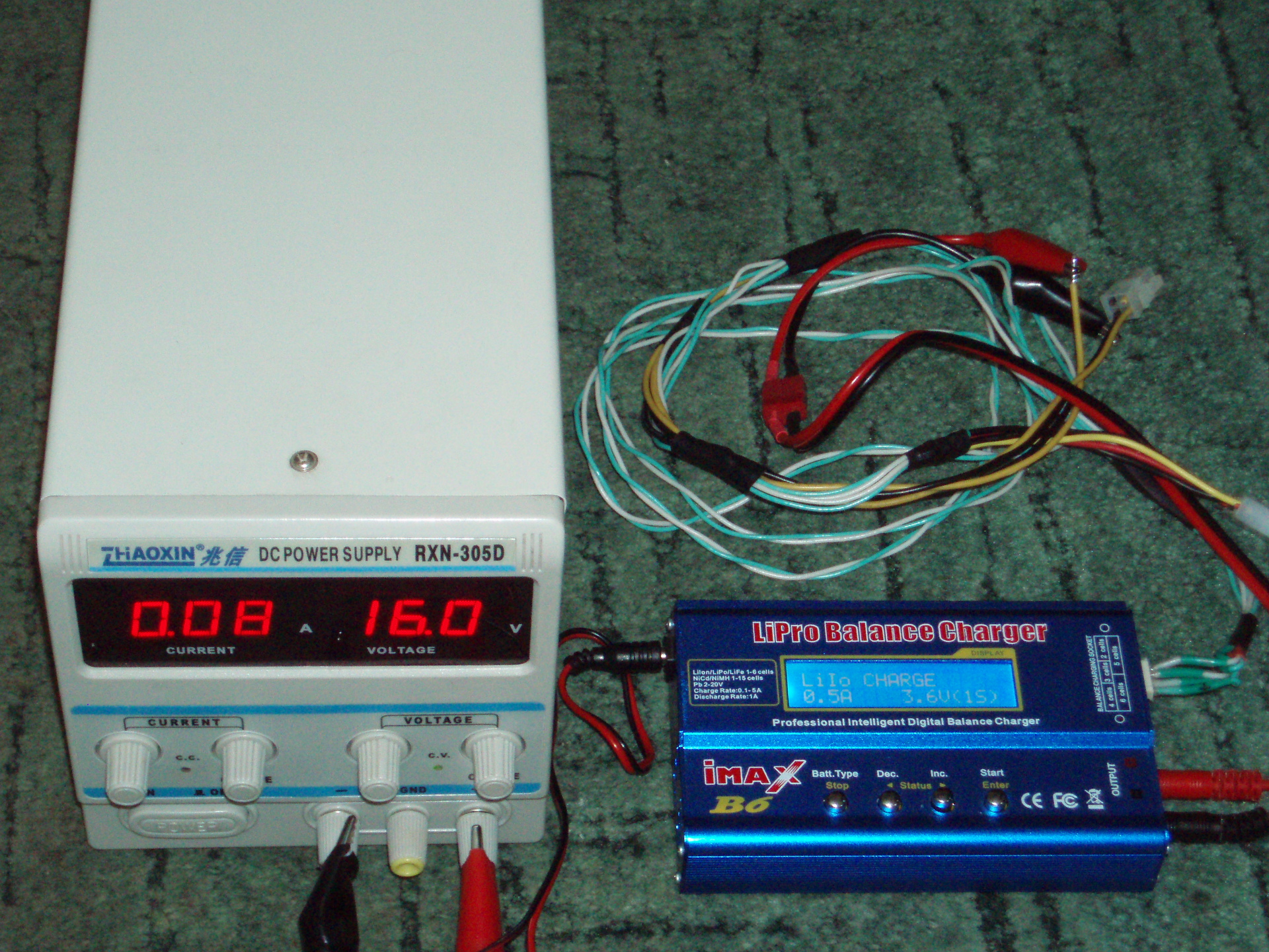
The lithium - polymer battery 12.6 V., 9800 mAh, 360 grams was used as a battery. The battery consists of 3 cells connected by a very cheap thin wire, charge controllers for each of the cells, a charging plug and a switch:

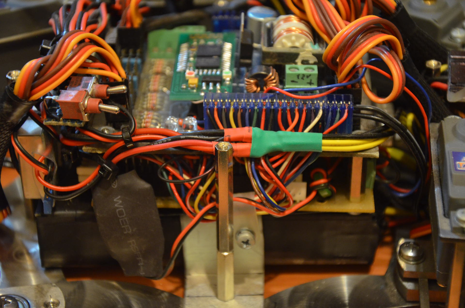
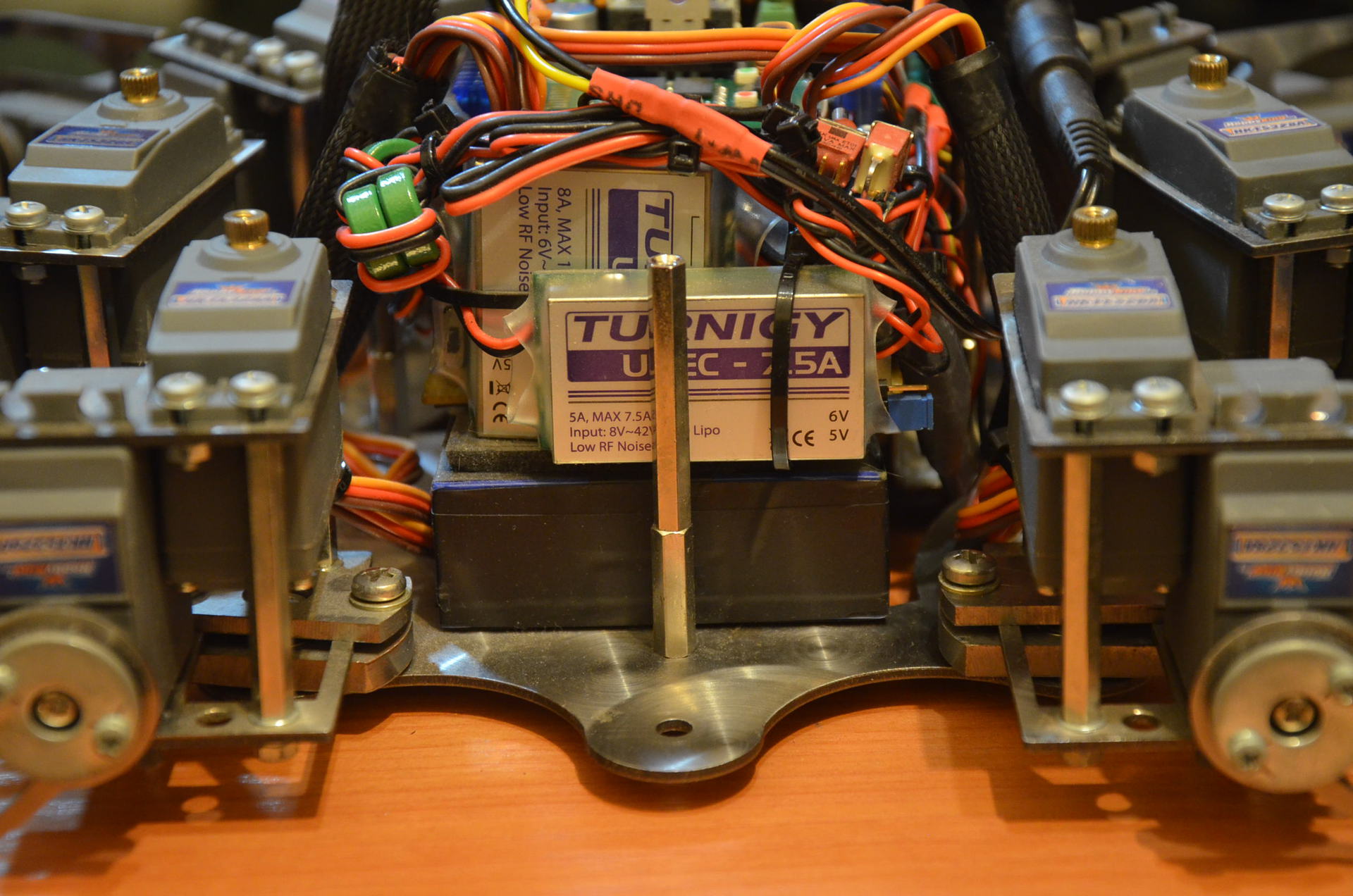
The charge controllers also limited the current delivered by the battery to 1A. It was planned to use iMAX B6 as a charger, so the charge controllers were removed and the conductors connecting the elements were replaced. The conductors from each element were also brought out in order to be able to charge the battery in a balanced way. DC-DC Turnigy UBEC-15A, DC-DC Turnigy UBEC-7.5A, DC-DC Turnigy Micro UBEC 5V / 3A were available from voltage converters. The first two are used to power the servos, the last converter is to power the control electronics.
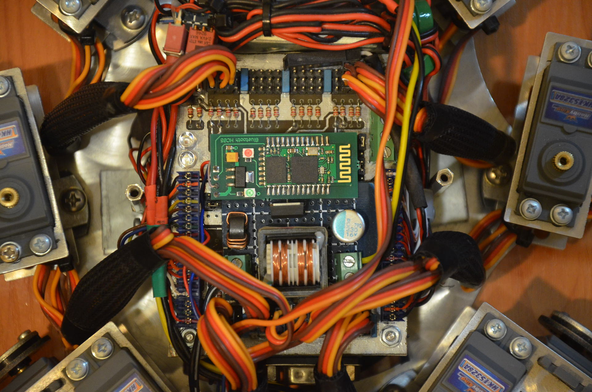
In the role of control electronics it was decided to use a very common project from the company LynxMotion - SSC-32. Since there was a MRC28 robot controller board, taken at the time from the RoboZone.su site, it was decided to build on it. An expansion card for the MRC28 for the SSC-32 project was found on the same site:
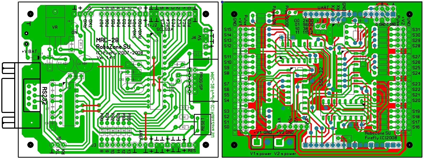
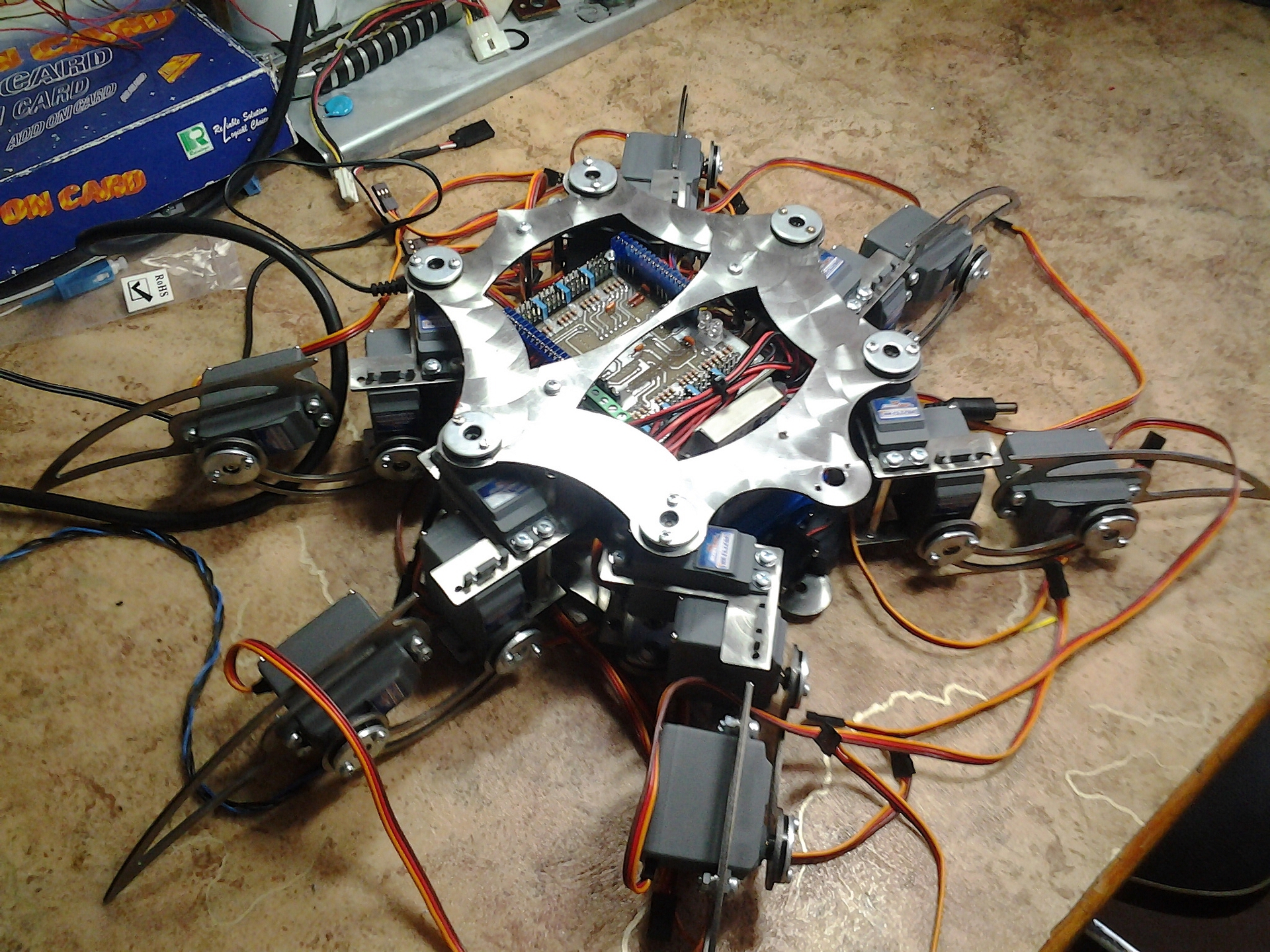
The expansion card was manufactured and connected to the controller board, fixed by double-sided tape on the battery. Voltage converters were connected, and the control part was pre-installed in the frame of the manipulator:
For the lower mounting of the limbs small bearings were used, taken from Japanese stepper motors (disassembly of old Japanese printers) and installed in a metal mount. For the most reliable contact Loctite 480 glue was used. A metal washer was used for a small gap between the bearing and the bottom of the frame. M5 mounting screw:
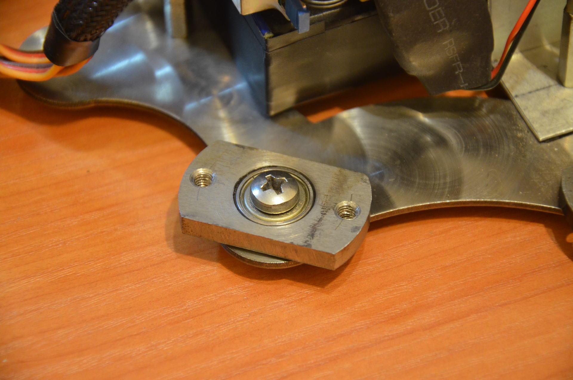
The extremity and fastening are interconnected by the type of clamp. So it was easier to implement and allowed to vary slightly when aligning the alignment between the servo shaft and the bearing:
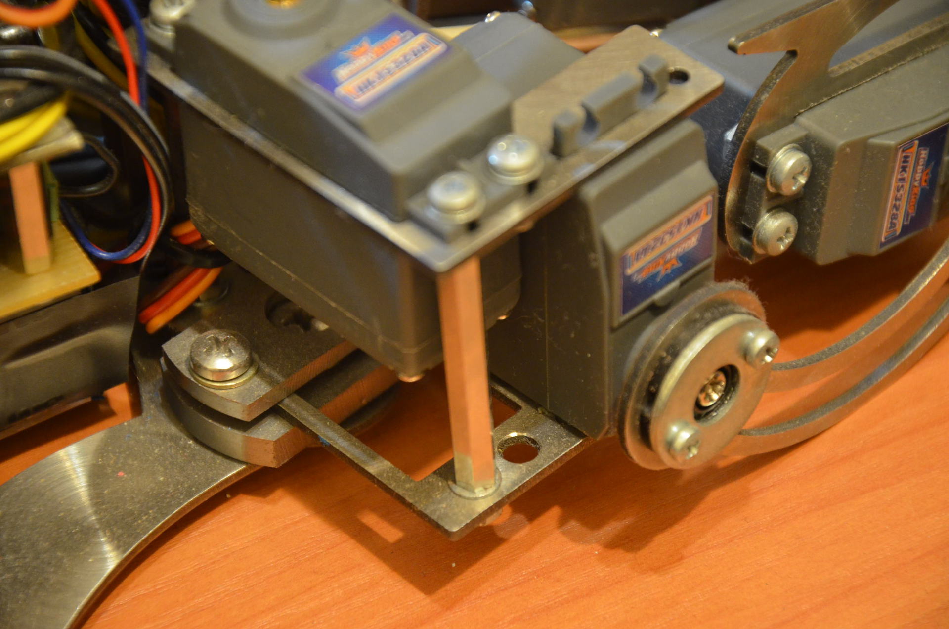
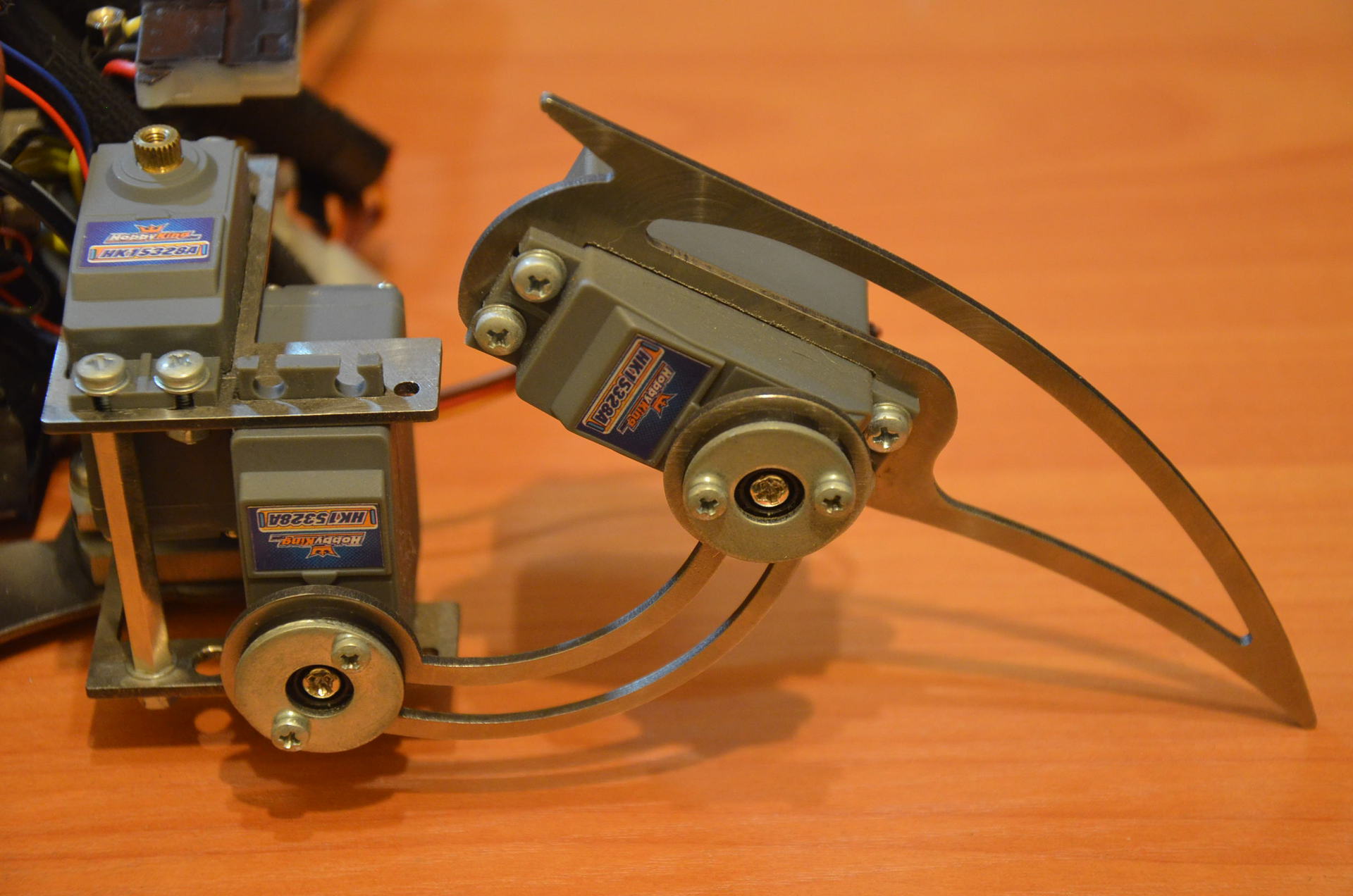
The overall construct of one limb acquired the following form:
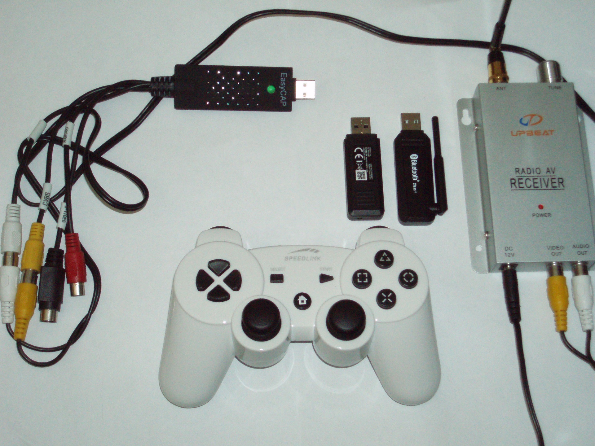
The HC-05 Bluetooth module and the Class 1 Bluetooth adapter were used to connect the PC to the manipulator. The simplest Chinese 2.4 GHz wireless analog camera with a receiver connected to the PC via a USB EasyCAP TV tuner was used to transmit the video. Image resolution 720x576. To control the manipulator was acquired wireless gamepad SpeedLink STRIKE FX.
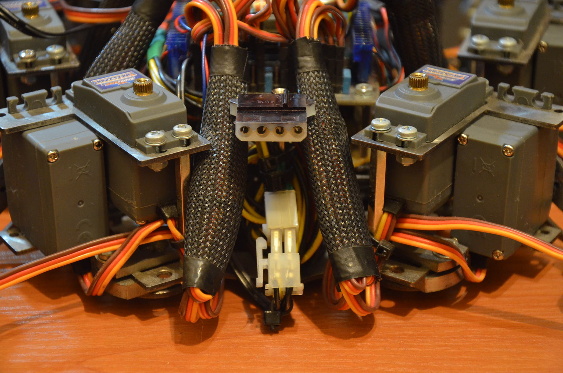
After soldering the supply conductors with connectors, all the wires were grouped and fixed with ties. The wires from the servos were covered with a nylon mesh. A voltage converter to 9V was used to power the camera. with LC-filter from improvised means, which allowed to almost completely get rid of the induced interference.
For mounting the battery (and the entire control electronics attached to it) to the body of the manipulator an aluminum bracket was arranged.
Below is a photo of the front side of the manipulator:
On the back side of the manipulator are the connectors for switching on and charging the battery:
The battery is charged by an external iMAX B6 controller set to a balanced charge mode and the RXN-305D power supply:
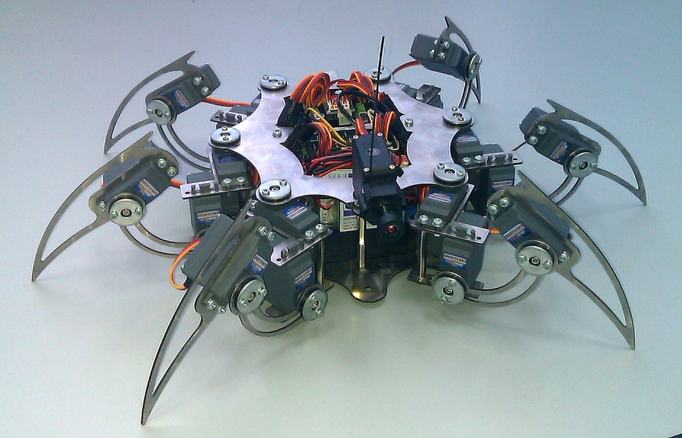
After flashing the controller, installing all the necessary modules and calibrating the limbs, the manipulator acquired the final look given below:
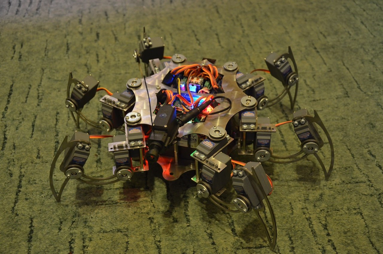
The final weight of the manipulator was ~ 3 kg. To rotate the camera was installed on the servo MG995. Operating time on one battery charge ~ 40 minutes. The video signal freely breaks 3-4 reinforced concrete walls. Communication range in open space ~ 30 meters.
PC software was developed by Microsoft Visual Studio 2008 and is a functional for managing, calibrating and displaying video data. The program allows you to control both a single servo and a group of joints.

All parameters used in the algorithms are displayed on a graphical interface. You can save / load calibration data for each limb. DirectShow was used to receive video data from the TV tuner (attempts to get a picture by means of OpenCV were unsuccessful). It was also necessary to install DXSDK_Jun10, and to connect to the project a library of work with graphics gdiplus. Virtual COM-port, implemented via Bluetooth, adequately earned with the Chinese Bluetooth-adapter only with the help of the SerialGate.dll library (most likely the problem is in the drivers or the adapter, but did not experiment with other adapters / drivers). The libraries hid.lib, hidpi.h, hidsdi.h, hidusage.h were connected to work with the gamepad (HID device).

To determine the values used by the gamepad keys, an additional software module was implemented:

Below is a video of the first movements of the manipulator and its further calibration with algorithm optimization and reduction of delays:
After minor improvements in the design and control program, the final implementation of the device is given in the following video:
The approximate cost of the whole set is ~ $ 400.
In conclusion, I would like to add that after conducting the above stages of developing a manipulator, certain experience was gained and appropriate conclusions were made. As in terms of the mechanics of movement, layout, filtering the supply voltage, and in the software part. When creating such a design in the future, both the hull design, and lighter materials, and faster servo drives, and more correct motion algorithms, and autonomous modes of operation with video data processing will be taken into account. But all this if there is free time in the future.
Thank you for your attention.
Source: https://habr.com/ru/post/254315/
All Articles