Another smart home, in three parts. Part two, software and server. + Bonus
In the first part, I talked about the iron part. Now it is time to talk about the software.
So, in the beginningthere was a word. There was a four-channel light switch, with different sensors connected to it. The physical interface is RS485. Over RS485 implemented a simplified version of MODBUS ASCII. Implemented only functions 03 and 06, in contrast to the standard addressing of byte registers starts from zero. Plus, added support for broadcast messages, the answer to which is not issued. They set the time, or all outputs are disabled. Through the RS485 adapter - RS232 controller was connected to the COM port.
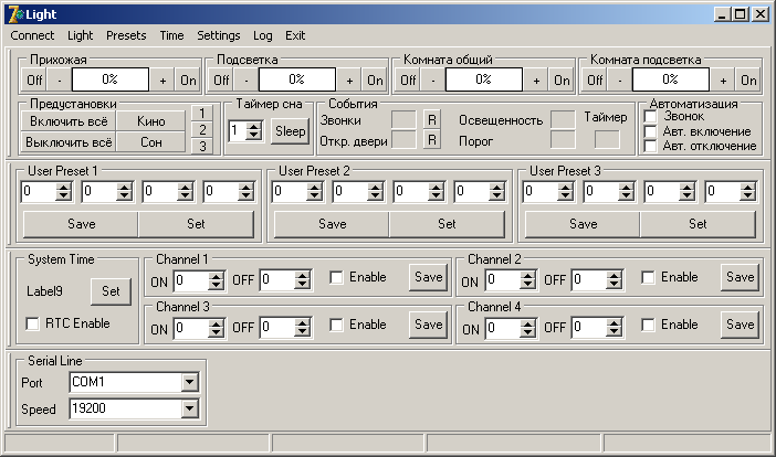
In those days, smartphones, tablets, and uniformity did not exist in browsers, so the very first version of the control program was for a regular PC. Here is this:
')
Everything was written in Delphi, a lot of buttons, a lot of digits, everything works, but there is one thing - why should I, at home, turn on the lights at home through a computer? Unclear. Therefore, the development of a network version has begun. And it turned out:
A small service was written that worked as a gateway between the Internet and the internal instrument network. The program has been finalized to work on the network. Everything is good, everything works, but there is one thing - why should you always carry a laptop or USB flash drive with the program to turn on the lights at home? Unclear. Therefore, further development continued. And it turned out:
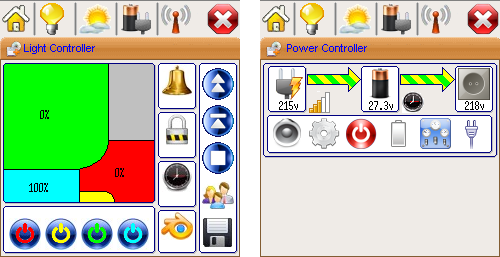
In those old times, smartphones were a rarity, browsers on mobile phones could do almost nothing, the maximum that could be calculated - J2ME. As an experiment, an ICQ client was added to the server part, and one of the many useful clients was also installed on the mobile phone. Everything worked, but every timesaying “OK, Google” to write on the telephone keypad “Home, turn on the lights in the hallway and show me the state of the other lamps and sensors” was not very comfortable. Therefore, the development of a J2ME application began, on the basic ideas of which one of the interfaces is now based. The bottom line was that there were several tabs or screens, each of which corresponded to one controller. Everything worked, everything was fine, but the next one appeared - the progress did not stand still, the browsers from the programs for displaying pages with pictures learned a lot more. And to keep three branches in parallel - Win32, J2ME and Web - was too lazy. Yes, and smartphones with tablets briskly walked around the planet. Therefore, the development continued and resulted in the final today:
In the client part, it was decided not to spray on different technologies, but to leave only one - HTML + JS. Fortunately, mobile and desktop browsers have learned to do a lot and most importantly - in the same way.
The ideology of the entire system was completely revised, if earlier the server part was just a gateway between the hardware and the application, now several additional tasks have appeared:
Also in the settings you can set the parameters, when changing which the server sent the letter, and recorded the event in the log. Having a base with accumulated values, you can build different graphs - temperature, for example, or voltage, or power consumption.
All this worked in my home, first in the Asus WL-500gP V2 router, interchanged with the firmware “from Oleg and enthusiasts” on which Lighttpd + PHP5 + MySQL were installed. A USB-RS232 adapter was connected to the router and ser2net was configured. The database stores settings and logs, admin and services are written in PHP. Then the Ethernet-RS485 gateway was developed, and it all moved to one of the cloud hosting sites.
Since there were a lot of pictures in the last part, I decided to tell about one of the projects in this part. At the same time we will consider the problems of scalability and the difference between wired and wireless interfaces, about which there was a lot of controversy in the last part. The project is important, but, unfortunately, with vague prospects. So, let's begin.
Suppose there is a plot. It has several lighting zones, such as the entrance, the path, the parking lot. Separately - the gate with an electric lock, and the entrance gate with electric drive. There is a garage so as not to waste your time on trifles - two floors, two lighting zones on each, and with separate heating. There is video surveillance and internet.
On the first floor are installed:
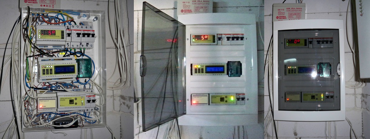
Above - a lighting and heating controller for the 1st floor, an RCD and a circuit breaker with an independent release. The second row is a power protection controller with a 100A relay, a 12V power supply from the bottom and an on-site lighting controller. At the very bottom is a two-channel receiver, which, through the lighting controller, allows you to turn on the light at the entrance and open the gate lock while on the street.
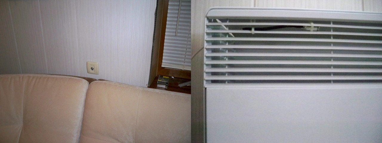
On the second floor:
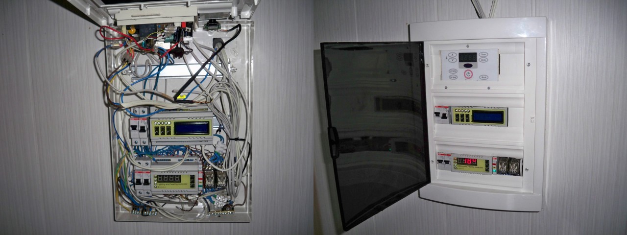
Top - electronics from the window air conditioner, it is in itself. The second row is the Ethernet-RS485 gateway, from the bottom - the second floor lighting and heating controller and power relays for convectors.
Temperature sensors indoors and coolant temperature (air from the convector in this case):
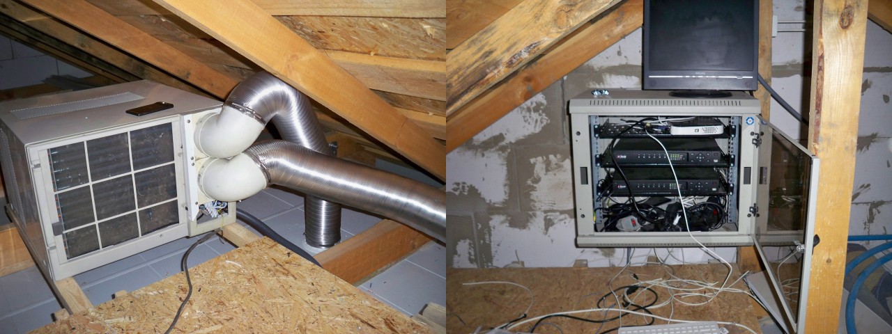
In the attic - air conditioning, video recorders, routers, antennas, fashion, and more:
All this worked well for the winter, spring came, and after it summer. And in the summer that the main thing? Brazier, gazebo and watering. A pit was dug, water valves were diluted in it:
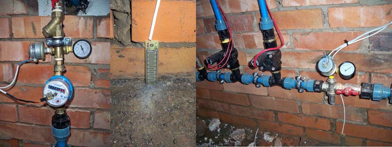
On the left - filter, inlet pressure sensor, water flow sensor. In the center there is a leakage sensor, on the right there are two irrigation valves, a pressure reduction gearbox and a pressure sensor downstream of the gearbox. Two controllers are installed - arbor lighting and water supply. In the arbor itself there are two zones - decorative lighting and main light:
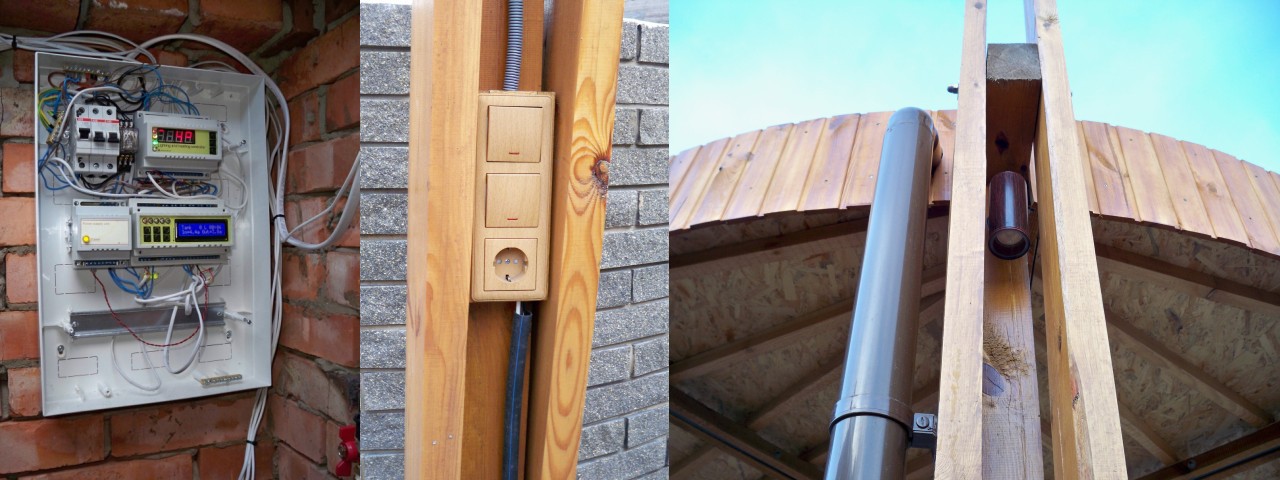
In the box above, there is an arbor lighting controller, in the center is a 24V power supply for valves and a water supply controller.
It turned out something like this - the second floor of the garage and a gazebo:

Between the pit and the rest of the controllers - about 15 meters, a wall of 30cm of aerated concrete and 10cm of the ceiling of the pit of reinforced screed. Wireless sensors and switches? No thanks. A 3x4 power cable and a 4x0.22 signal cable are stretched, connected to the power shield - and everything, there is light, watering, everything is controlled and shows the status of the sensors. As for me - no problems with scalability, nor with the lack of wireless technology.
With the software-server part on it all, in the next part I will describe the most interesting - the user interface.
So, in the beginning
In those days, smartphones, tablets, and uniformity did not exist in browsers, so the very first version of the control program was for a regular PC. Here is this:
Option 1: PC + Windows
')
Everything was written in Delphi, a lot of buttons, a lot of digits, everything works, but there is one thing - why should I, at home, turn on the lights at home through a computer? Unclear. Therefore, the development of a network version has begun. And it turned out:
Option 2: PC + Windows + Internet
A small service was written that worked as a gateway between the Internet and the internal instrument network. The program has been finalized to work on the network. Everything is good, everything works, but there is one thing - why should you always carry a laptop or USB flash drive with the program to turn on the lights at home? Unclear. Therefore, further development continued. And it turned out:
Option 3: PC + Windows + Internet + Mobile Phone
In those old times, smartphones were a rarity, browsers on mobile phones could do almost nothing, the maximum that could be calculated - J2ME. As an experiment, an ICQ client was added to the server part, and one of the many useful clients was also installed on the mobile phone. Everything worked, but every time
Option 4: LAMP + Internet + Web
In the client part, it was decided not to spray on different technologies, but to leave only one - HTML + JS. Fortunately, mobile and desktop browsers have learned to do a lot and most importantly - in the same way.
The ideology of the entire system was completely revised, if earlier the server part was just a gateway between the hardware and the application, now several additional tasks have appeared:
- Clients (either a script in a router or a gateway) periodically send their address to the server at which the server will work with them later. Kind of dyndns
- Once an hour, the server synchronizes the time on all controllers, since there is no real-time clock in them, but there is only software
- Once a minute, the server polls all controllers and writes answers to the database.
Also in the settings you can set the parameters, when changing which the server sent the letter, and recorded the event in the log. Having a base with accumulated values, you can build different graphs - temperature, for example, or voltage, or power consumption.
All this worked in my home, first in the Asus WL-500gP V2 router, interchanged with the firmware “from Oleg and enthusiasts” on which Lighttpd + PHP5 + MySQL were installed. A USB-RS232 adapter was connected to the router and ser2net was configured. The database stores settings and logs, admin and services are written in PHP. Then the Ethernet-RS485 gateway was developed, and it all moved to one of the cloud hosting sites.
Bonus
Since there were a lot of pictures in the last part, I decided to tell about one of the projects in this part. At the same time we will consider the problems of scalability and the difference between wired and wireless interfaces, about which there was a lot of controversy in the last part. The project is important, but, unfortunately, with vague prospects. So, let's begin.
Suppose there is a plot. It has several lighting zones, such as the entrance, the path, the parking lot. Separately - the gate with an electric lock, and the entrance gate with electric drive. There is a garage so as not to waste your time on trifles - two floors, two lighting zones on each, and with separate heating. There is video surveillance and internet.
On the first floor are installed:
Above - a lighting and heating controller for the 1st floor, an RCD and a circuit breaker with an independent release. The second row is a power protection controller with a 100A relay, a 12V power supply from the bottom and an on-site lighting controller. At the very bottom is a two-channel receiver, which, through the lighting controller, allows you to turn on the light at the entrance and open the gate lock while on the street.
On the second floor:
Top - electronics from the window air conditioner, it is in itself. The second row is the Ethernet-RS485 gateway, from the bottom - the second floor lighting and heating controller and power relays for convectors.
Temperature sensors indoors and coolant temperature (air from the convector in this case):
In the attic - air conditioning, video recorders, routers, antennas, fashion, and more:
All this worked well for the winter, spring came, and after it summer. And in the summer that the main thing? Brazier, gazebo and watering. A pit was dug, water valves were diluted in it:
On the left - filter, inlet pressure sensor, water flow sensor. In the center there is a leakage sensor, on the right there are two irrigation valves, a pressure reduction gearbox and a pressure sensor downstream of the gearbox. Two controllers are installed - arbor lighting and water supply. In the arbor itself there are two zones - decorative lighting and main light:
In the box above, there is an arbor lighting controller, in the center is a 24V power supply for valves and a water supply controller.
It turned out something like this - the second floor of the garage and a gazebo:
Between the pit and the rest of the controllers - about 15 meters, a wall of 30cm of aerated concrete and 10cm of the ceiling of the pit of reinforced screed. Wireless sensors and switches? No thanks. A 3x4 power cable and a 4x0.22 signal cable are stretched, connected to the power shield - and everything, there is light, watering, everything is controlled and shows the status of the sensors. As for me - no problems with scalability, nor with the lack of wireless technology.
With the software-server part on it all, in the next part I will describe the most interesting - the user interface.
Source: https://habr.com/ru/post/253965/
All Articles