20 years of building and maintaining a satellite network
Now it is difficult to believe in it, but some two decades ago it was considered a great success, if “by intercity” it was possible to get through the first time. Broadband access? Wireless Internet? Phone-communicator in your pocket for everyone? This is from somewhere in the "Half-Worlds" of the Strugatsky, I guessed right?
The very first antenna installed on the roof of the hangar of the All-Russian Energy Institute. In which I found the MiG-21 aircraft standing there and experimental stands that simulate lightning discharges.
And in 1995, the unknown company SFMT Ltd (which later grew up in Golden Telecom) began the construction of a “superimposed” (ie, operating in parallel with the national all-Russian) communications network. And as the main transport - it was decided to use its own satellite communication channels. The first channel, Moscow-Vladivostok, when launched, had a speed of only 128 Kbps (kilobits!). However, through this channel telephony was provided (including access to the World Access Card service of Sovintel, which was quite popular at that time), and the data transfer channel for the modem pool RussiaOnLine (SOVAM Teleport, a half-forgotten legend).
')
I'll tell you about the teleport, and its main components. Caution traffic : a lot of photos.
For quite a short time, the network grew by channels to such large cities as Khabarovsk, Tyumen, Ufa, Syktyvkar, Novosibirsk, Arkhangelsk, Nizhny Novgorod, Volgograd ... They did not forget about the smaller ones: Chelyabinsk, Perm, Cheboksary, Komsomolsk-on-Amur, Kazan, Lipetsk, Tula ... Following the appearance of channels - there also came the services of high-quality “voice” without any problems with dialing, and data transfer services. At the same time, one more direction began to develop: the provision of channels and services to large Clients located “on the edge of geography”: logging in Siziman Bay, oil production in the vicinity of Purpe and Lensk ...
In the meantime, the development of terrestrial (and above all - fiber-optic) networks did not stand still. Optics went further and further. Some satellite stations at the nodes were turned off and dismantled, some became centers ("hubs", "teleports") of their own satellite subnets.
Today's story is about one of the oldest satellite teleports in our network.
So, get acquainted: Moscow, Krasnokazarmennaya, 12.
Here are three more antennas and equipment in containers at our facility:

The first from the image above is “in reserve” to pick up the channels in case of any unforeseen situations. The last time in this role - she worked in the accident satellite Express MD1
Mirrors are large: the larger the diameter of the mirror, the greater the gain of the antenna. Remember the usual pocket flashlight: with the same light bulb - the one with a larger mirror will shine on. A large gain (or, in this case, the same thing - greater sensitivity) is very important for satellite communications.
The leftmost antenna with the photo above is 11 meters in diameter. For scale, look at the windows of the building, or the cellular antenna on the brick railing next to it. This antenna is the largest here (and according to unconfirmed rumors, it is almost the only antenna of such diameter in the world installed on the roof, and not on the ground).
In general, one of the largest antennas in Russia, with a diameter of 64 meters, is located on the Bear Lakes. Where we have another teleport:
Here in this old photograph is Nikolay Nikolayevich Vinogradov, the luminary of satellite communications, and I am against this antenna.

This antenna (Andrew, diameter 7.3 m) is the legacy of Comink-Combellga. Here we brought her from the Cows Shaft. We drove without dismantling at night. They blocked the movement along the entire route, checked that everything fit in with everything in size with a small margin (the wires did not hang, gas pipelines and other details did not interfere), put on the trailer - and dragged along with the traffic police tuple. We got to the building simply, but the last 50 meters was a real circus. But they did, of course.
"The very first" below and the antenna "from the Cow Shaft"

This antenna (Vertex, diameter 7.2 m) - here appeared the second. And at first she worked in the C-band, and then she was successfully remade to work in the Ku band. It is a little more complicated than a similar remake of the “television” plate: it was necessary not only to change the feed, but also to “re-drag” the geometry of the mirror surface again.
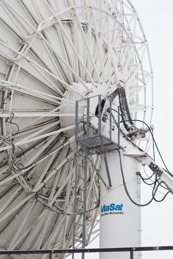
This is one of the two local antennas, equipped with satellite tracking system.
For antennas with a wide radiation pattern - this “eight” entirely falls inside the antenna beam. And for antennas with a narrow diagram (i.e. antennas with large mirror diameters, remember?), It is often necessary to fine-tune the position in accordance with the current position of the satellite. This is done with the help of such drives:
Automatic tracking automatically evaluates the level of the signal coming from the satellite, the current position of the antenna, and, if necessary, includes actuators that move the mirror in two directions (“in azimuth” and “in elevation”). Thus, the antenna always remains directed to the point of the sky where the satellite is now located.
The antenna has an anti-icing system that prevents the accumulation of ice and snow on the mirror and the irradiator. Now about -4 degrees Celsius outside, it is sleet. Water flows from the plate, here:

The small box in the center of the photo is a weather sensor. It is necessary then that the conditions for the formation of frost arise only in a narrow temperature range: from minus 5 to plus 5 degrees. Well, if at the same time there is precipitation, of course. At temperatures above 5 degrees Celsius, everything just flows, and when it is below minus five, the snow is dry, it just slides off the mirror. Antenna heater power is 25kW; so that the correct operation of this small box - can significantly reduce electricity bills.
Now look closely here, to the very top:
No cable goes there - this is not yet a receiver, this is a counter reflector; an indispensable attribute of the so-called. "Two-mirror antenna".
Two-mirror antennas are more complex in design, but compared to “single-mirror” antennas, the so-called “Surface utilization factor” of a mirror.
Below, right in the center of the mirror itself - the antenna feed:
In general, the original irradiator was not so “fluffy”, but we had to modify it. The fact is that its output is closed with a radio-transparent film, which has a really magical attraction for the crows. Not understanding such simple safety rules as “do not get into focus while the transmitter is on,” they happily sit down and begin to peck off the film. The irradiator and the entire waveguide path are under constant overpressure of specially dried air. As is well known, water and moisture are electrically conductive, and the ingress of moisture into the waveguide is equivalent to getting there a decent piece of metal. And if the crow with its armor-piercing beak punches a hole in the film ... In general, the crow has chances to interfere in someone's banking transaction. And with these “hairs” the problem is almost completely solved. Almost - because the film is still very tempting for them to look.
A lot of cables fit the antenna: radio frequency, power, control, control ...
Antenna's “sub-mirror cab” - a view from the inside:
The “pipeline” down is the receiving part, one of the LNA is visible (a rectangular box at the very bottom). Thick cable - output signal from the LNA redundancy switch. "Pipeline" in the middle - the transmission path. A flexible wave guide (left) fits it. And straight ahead, the antenna feed.
High-frequency cable (top) and "semi-rigid" elliptical waveguide C-band (bottom):

Waveguides are flexible:
Compared with the hard or "semi-rigid" - they have significantly more losses. But the use of flexible waveguides (or sections of flexible highways between two rigid) - increases the simplicity and ease of installation.
Radio equipment, as well as antenna control systems, are located in containers near the antennas:

From the entrance we are greeted by “a system of solid state power amplifiers with a 100% reserve. The power amplifier (aka "transmitter") - in fact, allows the antenna to go on the air.
Another transmitter, but no longer a “solid-state” (transistor), but a tube one .
Believe me, it is not installed for the sake of the famous “warm tube sound”! Amplifiers on transistors - just recently began to catch up on their parameters on the amplifiers on the lamps. For example: the transistor at the top - has a maximum power of 140W, and the tube at the bottom - 700W. With the same dimensions and about the same consumption - agree, the difference is very significant. The advantage of transistors is greater linearity. None of the amplifiers work at maximum power, due to the occurrence of nonlinear distortion in it (and this is death for the “phase modulation” used in satellite communications). To obtain a known linear mode, a transistor amplifier can be “overclocked” by no more than half the maximum power. Lamp same - no more than a quarter. But all the same: half of 140W - this is noticeably less than a quarter of 700W.
Here is the whole rack:
The gray thing under the transmitter is an air dryer that keeps the waveguide paths in working condition.
And now the rest of the container equipment:

These are the air ducts of the transmitter's cooling system:

Handle on the box see? Also our “know-how”: this is the brand switch of the “winter-summer” modes. It is cold in winter, and the equipment loves room temperature too. Well, yes, you can put a heater, but why? He turned the handle - and warm. And in the spring knob is spinning to another position; and air conditioners together say "thank you, master!"
Here is the control unit for the distribution of the waveguide paths. Adjustment of giving - is made by rods with balls (below). Estimate the air flow (and at the same time - the presence of a strong leak) can be on the scales, past which the balls "float":
These are the inverter cables coming from the modems in the equipment room, located four floors below. On large nodes - we use the scheme with “PCh70 / 140MHz”, it is simpler and easier than the scheme with “PCh L-Band”. Each pair of cables is the reception and transmission of one transponder.
Stand behind:

And another one:
Thick corrugated cable is the input of the receiving signal coming from the low-noise amplifier of the antenna. Why is a low noise amplifier? Theory of radio engineering says: "the noise of the whole system - there can not be less than the noise of its first amplifier stage". To detect a received signal, a certain signal-to-noise ratio is required. And the less self-noise the system adds, the less power will be required from the satellite for the error-free transmission of the same signal.
High-frequency cable from the LNA antenna.

High-frequency cable from the antenna LNA, and high-frequency splitter.
Splitters - share high-frequency signals between converters of different transponders.
One more, but - already for IF signals.
Power cable and control of LNA redundancy system
Two stands away are our first transmitters. Klystronic, C-band, power as much as 3 kW each. I will say right away: at full capacity - they have never worked. But after the next gnawed film - itching very much to turn them on, and to fry a couple of “karkush” on the fly:
Top - switch and waveguides of the backup system; and load for the "spare" transmitter. Load with forced cooling: if the “spare” transmitter operates “in hot standby” (ie it emits exactly the same as the “main” one), all its power is dissipated on the load.
A fan is used for cooling:

For high-power transistor transmitters - usually used so-called. “Semi-hot” reserve: the “spare” transmitter does not radiate. In this case, a switch is installed in the redundancy system, simultaneously switching both the waveguide output of the transmitter and its coaxial input. It looks like this:

The round little thing on the left is the electric drive for the switch.
Below - the "waveguide" part of the switch, on top - "coaxial". The input of the idle transmitter is connected to the load (silver, in the foreground), which does not allow the transmitter to catch interference from the air.
The connector through which the switch signals are sent to the switch, and from which the backup system receives information about the current position of the switch.

Here is the device in the rack, in operation:
Now back to the roof again, and walk around the antennas:
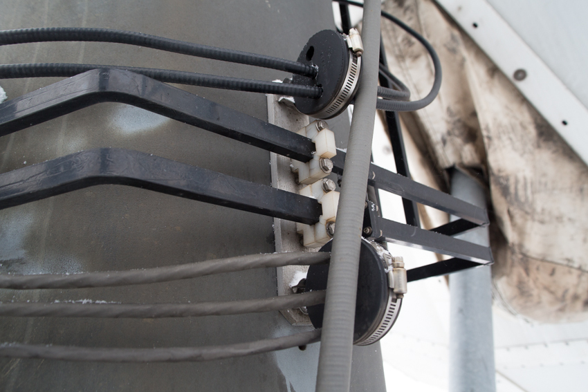
High-frequency cables (top), “hard” Ku-band waveguides (rectangular in the middle), control and power cables for LNA.
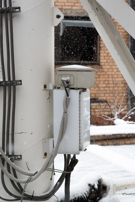
Distribution box on the "foot" of the antenna.
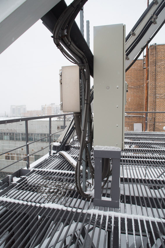
The same, but in a more solid form of "electrical cabinet"
In such boxes and cabinets - plant the power cables of the antenna equipment, auto-tracking system, and antenna anti-icing systems. Well, be sure to - inside there is a very useful thing: a socket for connecting power tools, lighting, etc.
If 220V power is supplied to the antenna, we almost always put similar boxes or shields near the antenna. Additional costs are small, and a lot of amenities during construction and operation.
Now - the next construction.

This is a C-band antenna, so it is so big. Naturally, you should not even try to use such an antenna without an auto-tracking system.
Cable, "twisting" mirror - the power of the anti-icing system (on this antenna - it is made in the form of "heating mats")

A separate story is associated with the installation. Such antennas are naturally assembled on the ground. In our case, the assembly was carried out here, between these buildings. From the edge of the mirror to the walls was no more than half a meter.
Then it was lifted by a crane. Like this:
Naturally, the crane operator behind the edge of the roof - did not see where to put it, but it was necessary to get on the metal "ears", with a tolerance of a couple of millimeters.
Like this:
The operation was the hardest. And as I have already said, this is almost the only antenna of such diameter in the world, installed not on the ground, but on the roof of a high-rise building.
The irradiator of this antenna. See how his birds gnawed? Yes, it took them almost 15 years to do this; but I say: the crow's beaks are armor-piercing.
And there is a faint edge over there. It was either the crows got to the film again, or the remnant of the previous radio transparent film. I'd like to believe in the latter; However, after a couple of days, you will need to carry out maintenance work. And here it is also interesting. Serving such an antenna, and in particular its feed, is not an easy task. Ahead - the abyss of 12 floors, remember? You can, of course, turn the antenna sideways, towards the roof. But the fact is that the auto maintenance drive does not allow you to quickly move the antenna. Rotate 90 degrees - will take several hours; And the drive for such essential turns is not intended.
Therefore - we had to reinvent a little again.
"Regular" drive - disconnects:
Instead, he put homemade temporary: small, but very fast. He turns the antenna to the desired angle in just five minutes.
To prevent the antenna from winding down with an occasional gust of wind, at the time of disconnecting the main drive, and at a time when the entire antenna is held on “self-made fast” - the antenna column is fixed to the “temporary anchor”:

In the eye above - one of the “ears” of the antenna enters, to which a regular drive clings. The whole structure is fixed with a finger (hanging at the bottom of the eyelet). All wind gusts are no longer scary to us.
On the side of the antenna, we made a special "tilting" area.

We turn off the transmitters, turn the antenna to the site with an additional drive, “tilt” the site into the mirror - and now the irradiator is easily accessible for any work, repair and maintenance. Simple, reliable, convenient and safe!

- Why do you need such a large and expensive object?
That communication was also where there are no land lines of communication. Or they are, but small capacity, poor quality, or very expensive.But there are still many such places in Russia: even large cities like Petropavlovsk-Kamchatsky, Magadan, Anadyr, Norilsk - do not have land channels (of sufficient capacity). What to speak about the villages in Yakutia or in the Far East, or about the gas production complexes in Siberia. And this is not only for cellular communication: ipvpn or Lan2Lan is very popular among the same drillers; first of all for monitoring such complex objects as drilling. And you can talk via Skype ... Yes, satellite channels can not be compared with optics in terms of bandwidth: a satellite channel with a speed of 10 Mbps is considered very wide. Can I do more? It is possible, we have channels both 100 and 200 Mbit each. But this, above all, is a very expensive pleasure.
- At each base station put on FSS?
Not necessary.If there is a group of BSs that are interconnected by terrestrial channels, then for the operation of the whole group, a single JSSS is sufficient; how this is done, for example, here in Bovanenkovo (http://habrahabr.ru/company/beeline/blog/247773/).
But sometimes it is easier and cheaper to build two ZSSS, than to try to lay a landline between two points. For example, Keperway Airport is, according to Wikipedia, only 32km from Bilibino. But to stretch the channel from there to Bilibino is almost impossible, and therefore we have another ZSSS there.
- How does satellite communication work?
A satellite is a kind of mirror that looks at a certain territory: the so-called. "Service area". And in principle, any two stations located within this territory can communicate with each other. Actually, this is the main beauty of satellite communications: distances are not important to it. The correspondent station may be located on the neighboring house, or maybe thousands of kilometers from the “center”; for satellite communications - it makes no difference.
Transmitting station - broadcasts the signal to the satellite. The host picks it up, decodes it, and transmits the received data towards the user. If the communication system is bidirectional (and not broadcast, as, for example, “satellite TV”), then in the opposite direction, everything works the same way.
The most typical scheme for building satellite networks is the so-called. "Star": many small stations in the district, and "center" with a large antenna in the middle. But there are also communication systems capable of working on the principle of “everyone with everyone”.
From the point of view of the organization of satellite channels - they can all be divided into two types: systems with "fixed channels", and "systems with the provision of a channel on demand." The former are commonly used on trunk links, the latter are used on circuits with low or very irregular traffic. And the main criterion here is not the type of traffic or its consumer, but the nature of the traffic. The same BS: if the BS is located in a large village, then it is usually connected via a “fixed channel”. If the BS is installed in the village, where only about a dozen people, then it makes sense to use the system "provide channels on demand."
- What does it consist of and how does the ZSSS work?
All satellite communication stations have a similar device, and consist of almost the same functional components.
"The reception path." The satellite signal received by the antenna enters the antenna feed. There are three devices in the illuminator: a polarization selector, a diplexer and filters. The polarization selector selects the polarization we need, the diplexer separates the transmit and receive signals, the filters cut all unnecessary (in the receive path the transmit frequencies and vice versa).
The filtered signal - comes to the low-noise amplifier. The parameters of which, as we recall, actually determine the quality of the work of the entire receiving system as a whole.
From the output of the LNA, the signal goes to the “down converter”, where it is transferred from “high frequency” (4 GHz for the C band, and 11 GHz for the Ku band) - to a lower “intermediate frequency”. Depending on the scheme of a specific ZSSS - it may be different. Several steps of conversion can also be used - it all depends on what needs to be done and how it can be done most conveniently and efficiently.
Next, the signal enters the demodulator, which converts the analog terrestrial signal into a digital stream.
Since the satellite channel operates at very low signal-to-noise ratios, the probability of error in the received stream (channel) does not exceed 1E-3. If such a channel is immediately sent directly to the end user, then nothing will work. Therefore, on any satellite channels - powerful noise-resistant coding is used; and the next required link is a decoder. The decoder corrects errors, and the stream received already “almost error-free” (with an error probability no worse than 1–8) sends it through a standard interface to the terminal data equipment. That's all you want: a computer, a packet switch, a BS ...
"Transmission path". All the same, only in the opposite direction. The signal from the data terminal equipment - through the standard interface goes to the encoder. The coder imposes on the incoming data - a certain amount of “redundant information”, which then will allow the decoder to correct errors that have occurred in the channel. The resulting stream gets to the modulator, which turns the digital stream into an analog signal.

Then this signal goes to the “up converter”, from it to the power amplifier. The amplified signal through the diplexer and the polarization selector enters the antenna feed. And from there to the sky, to the satellite.
Each “function block” is not necessarily a separate element or device. One unit can perform several functions. For example, “LNA + Converter Down” is a so-called. “Low Noise Converter” (LNC), “Converter Up + Power Amplifier” is a “block-upconverter” (BUC), “demodulator + modulator + codec + interface” is a “modem”. Up to the point that all the devices shown in the figure can be combined within one small case, as in the “satellite phones” of the Iridium or Thuraya systems.
Depending on the purpose of a specific ZSSS, there may be many similar functional devices on it: modems, converters, amplifiers. If the SCSS is used only for reception, then the entire lower part of the picture, related to the transmission path, is completely absent in it.
About the roof, antennas and radio equipment - for now. Then, according to the tour plan, find out where the IF cables go and what the modems look like. This and a little work with the oscilloscope will be in the second part, if you are interested, and then the post already and so it will turn out to be very heavy.
The very first antenna installed on the roof of the hangar of the All-Russian Energy Institute. In which I found the MiG-21 aircraft standing there and experimental stands that simulate lightning discharges.
And in 1995, the unknown company SFMT Ltd (which later grew up in Golden Telecom) began the construction of a “superimposed” (ie, operating in parallel with the national all-Russian) communications network. And as the main transport - it was decided to use its own satellite communication channels. The first channel, Moscow-Vladivostok, when launched, had a speed of only 128 Kbps (kilobits!). However, through this channel telephony was provided (including access to the World Access Card service of Sovintel, which was quite popular at that time), and the data transfer channel for the modem pool RussiaOnLine (SOVAM Teleport, a half-forgotten legend).
')
I'll tell you about the teleport, and its main components. Caution traffic : a lot of photos.
For quite a short time, the network grew by channels to such large cities as Khabarovsk, Tyumen, Ufa, Syktyvkar, Novosibirsk, Arkhangelsk, Nizhny Novgorod, Volgograd ... They did not forget about the smaller ones: Chelyabinsk, Perm, Cheboksary, Komsomolsk-on-Amur, Kazan, Lipetsk, Tula ... Following the appearance of channels - there also came the services of high-quality “voice” without any problems with dialing, and data transfer services. At the same time, one more direction began to develop: the provision of channels and services to large Clients located “on the edge of geography”: logging in Siziman Bay, oil production in the vicinity of Purpe and Lensk ...
In the meantime, the development of terrestrial (and above all - fiber-optic) networks did not stand still. Optics went further and further. Some satellite stations at the nodes were turned off and dismantled, some became centers ("hubs", "teleports") of their own satellite subnets.
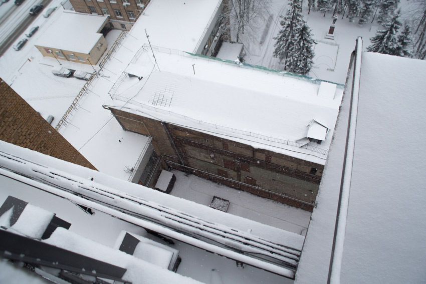
Today's story is about one of the oldest satellite teleports in our network.
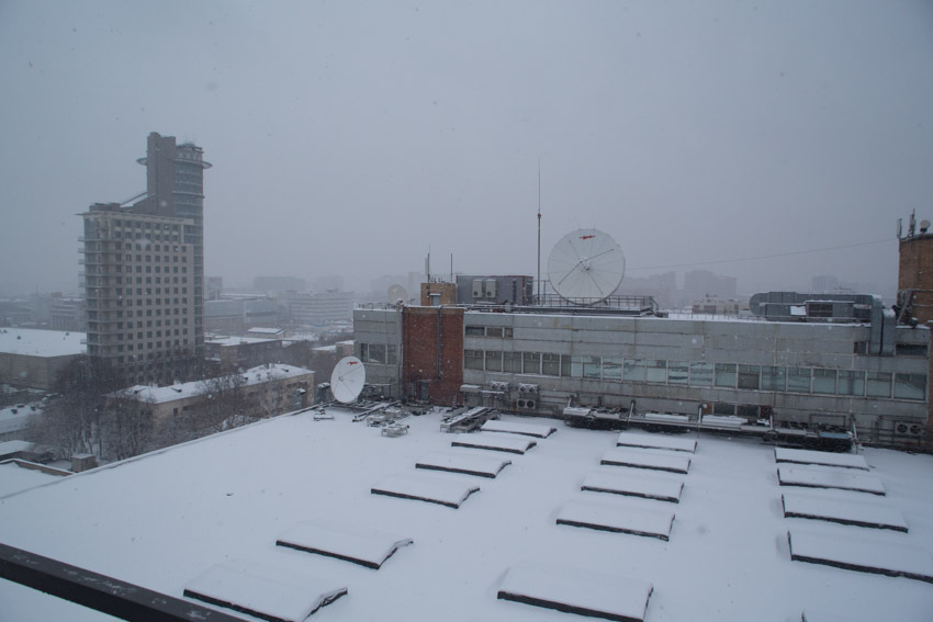
So, get acquainted: Moscow, Krasnokazarmennaya, 12.
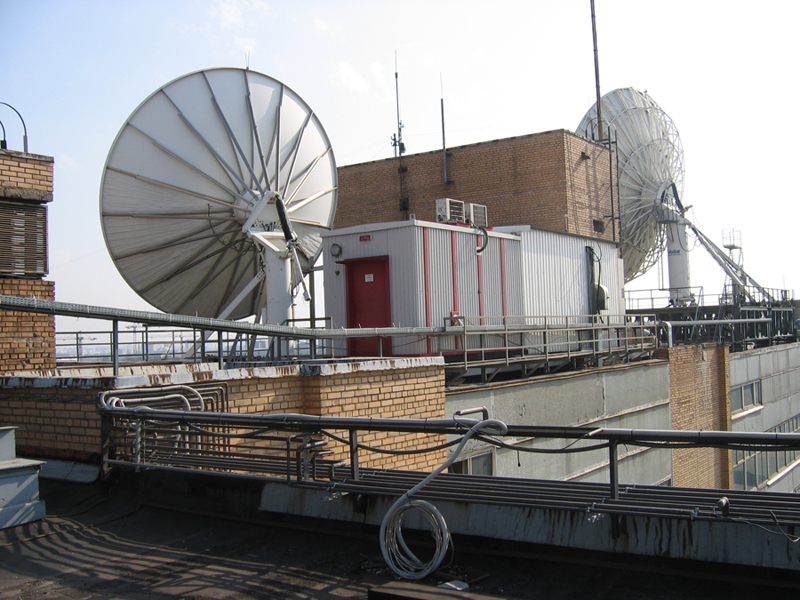
Here are three more antennas and equipment in containers at our facility:
The first from the image above is “in reserve” to pick up the channels in case of any unforeseen situations. The last time in this role - she worked in the accident satellite Express MD1
Mirrors are large: the larger the diameter of the mirror, the greater the gain of the antenna. Remember the usual pocket flashlight: with the same light bulb - the one with a larger mirror will shine on. A large gain (or, in this case, the same thing - greater sensitivity) is very important for satellite communications.
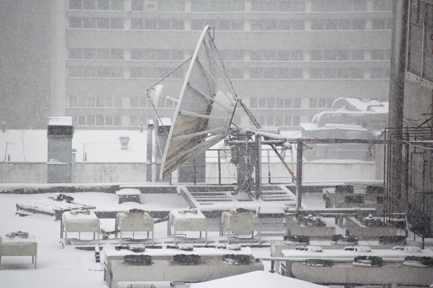
The leftmost antenna with the photo above is 11 meters in diameter. For scale, look at the windows of the building, or the cellular antenna on the brick railing next to it. This antenna is the largest here (and according to unconfirmed rumors, it is almost the only antenna of such diameter in the world installed on the roof, and not on the ground).
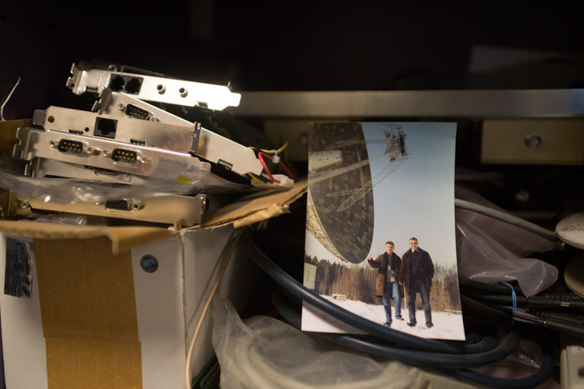
In general, one of the largest antennas in Russia, with a diameter of 64 meters, is located on the Bear Lakes. Where we have another teleport:
Here in this old photograph is Nikolay Nikolayevich Vinogradov, the luminary of satellite communications, and I am against this antenna.
This antenna (Andrew, diameter 7.3 m) is the legacy of Comink-Combellga. Here we brought her from the Cows Shaft. We drove without dismantling at night. They blocked the movement along the entire route, checked that everything fit in with everything in size with a small margin (the wires did not hang, gas pipelines and other details did not interfere), put on the trailer - and dragged along with the traffic police tuple. We got to the building simply, but the last 50 meters was a real circus. But they did, of course.
"The very first" below and the antenna "from the Cow Shaft"
This antenna (Vertex, diameter 7.2 m) - here appeared the second. And at first she worked in the C-band, and then she was successfully remade to work in the Ku band. It is a little more complicated than a similar remake of the “television” plate: it was necessary not only to change the feed, but also to “re-drag” the geometry of the mirror surface again.
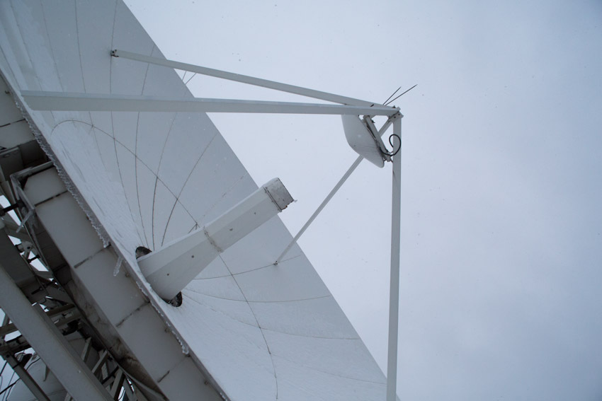
This is one of the two local antennas, equipped with satellite tracking system.
The satellite, although it is called "geostationary" - from the point of view of an earthly observer, writes out a kind of "eight" in the sky. The amplitude of this “eight” is determined by the accuracy of holding the satellite in the orbital position. And the accuracy of the retention itself is directly related to the reserve of the “working fluid” (or “fuel”) at the satellite. From which, in turn, the “period of active existence” of a satellite in orbit almost directly depends.
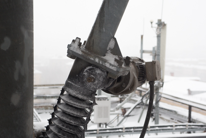
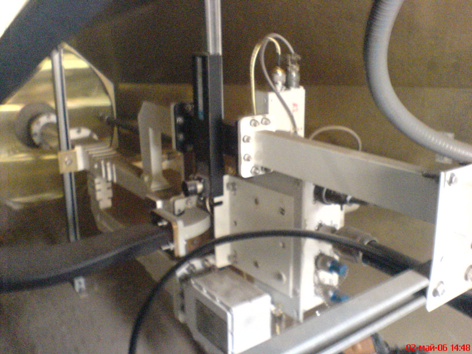
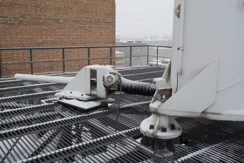
For antennas with a wide radiation pattern - this “eight” entirely falls inside the antenna beam. And for antennas with a narrow diagram (i.e. antennas with large mirror diameters, remember?), It is often necessary to fine-tune the position in accordance with the current position of the satellite. This is done with the help of such drives:
Automatic tracking automatically evaluates the level of the signal coming from the satellite, the current position of the antenna, and, if necessary, includes actuators that move the mirror in two directions (“in azimuth” and “in elevation”). Thus, the antenna always remains directed to the point of the sky where the satellite is now located.
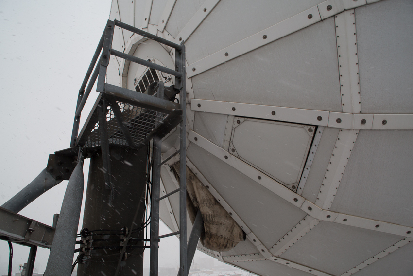
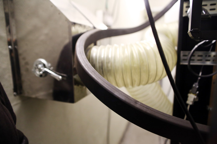
The antenna has an anti-icing system that prevents the accumulation of ice and snow on the mirror and the irradiator. Now about -4 degrees Celsius outside, it is sleet. Water flows from the plate, here:
The small box in the center of the photo is a weather sensor. It is necessary then that the conditions for the formation of frost arise only in a narrow temperature range: from minus 5 to plus 5 degrees. Well, if at the same time there is precipitation, of course. At temperatures above 5 degrees Celsius, everything just flows, and when it is below minus five, the snow is dry, it just slides off the mirror. Antenna heater power is 25kW; so that the correct operation of this small box - can significantly reduce electricity bills.
Icicles from the antenna ... On the edge of the mirror of one of the local antennas - after heavy snowfalls, a real “ice waterfall” is formed - the snow that melts due to the system’s operation slips down - and freezes like a stalactite around the edge. And from below - as usual, an ice stalagmint stretches to it from the site. And sometimes it comes to the fact that all this turns into an “ice stalagnat” connecting the plate and the platform. This does not interfere with the work; This antenna does not use auto tracking. And if I had used it, then all this beauty would have collapsed after the first cycle of antenna tuning. So this is neither good nor bad - it just looks very nice and funny.
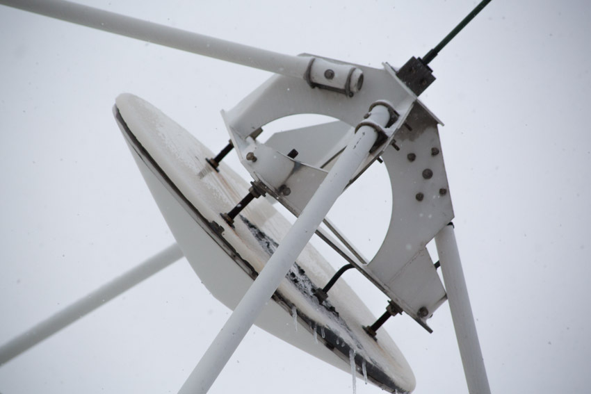
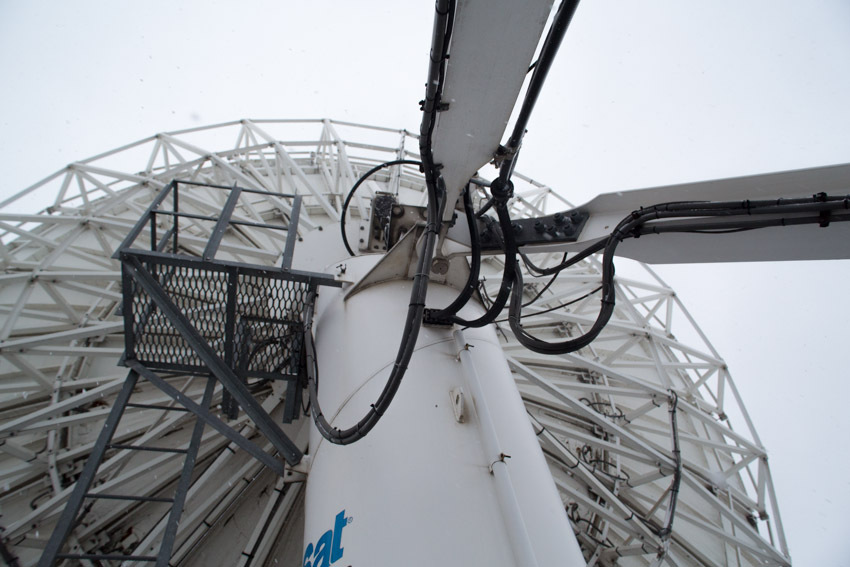
Now look closely here, to the very top:
No cable goes there - this is not yet a receiver, this is a counter reflector; an indispensable attribute of the so-called. "Two-mirror antenna".
Two-mirror antennas are more complex in design, but compared to “single-mirror” antennas, the so-called “Surface utilization factor” of a mirror.
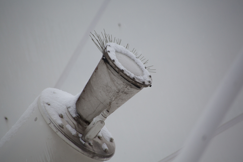
Below, right in the center of the mirror itself - the antenna feed:
In general, the original irradiator was not so “fluffy”, but we had to modify it. The fact is that its output is closed with a radio-transparent film, which has a really magical attraction for the crows. Not understanding such simple safety rules as “do not get into focus while the transmitter is on,” they happily sit down and begin to peck off the film. The irradiator and the entire waveguide path are under constant overpressure of specially dried air. As is well known, water and moisture are electrically conductive, and the ingress of moisture into the waveguide is equivalent to getting there a decent piece of metal. And if the crow with its armor-piercing beak punches a hole in the film ... In general, the crow has chances to interfere in someone's banking transaction. And with these “hairs” the problem is almost completely solved. Almost - because the film is still very tempting for them to look.
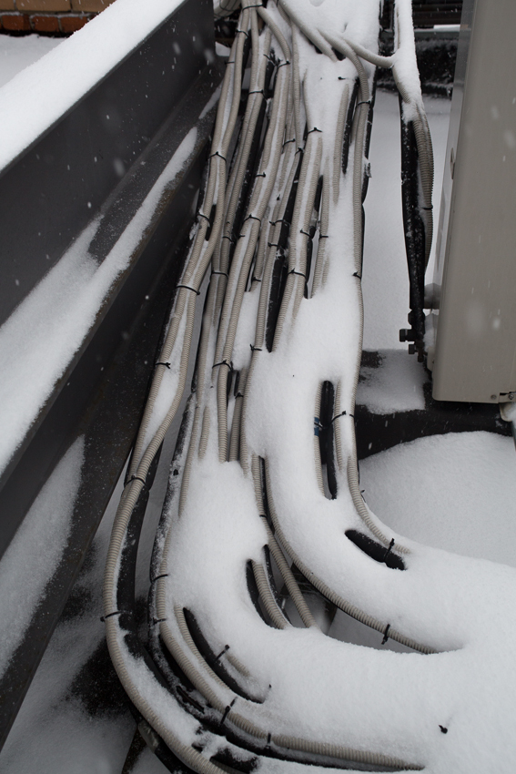
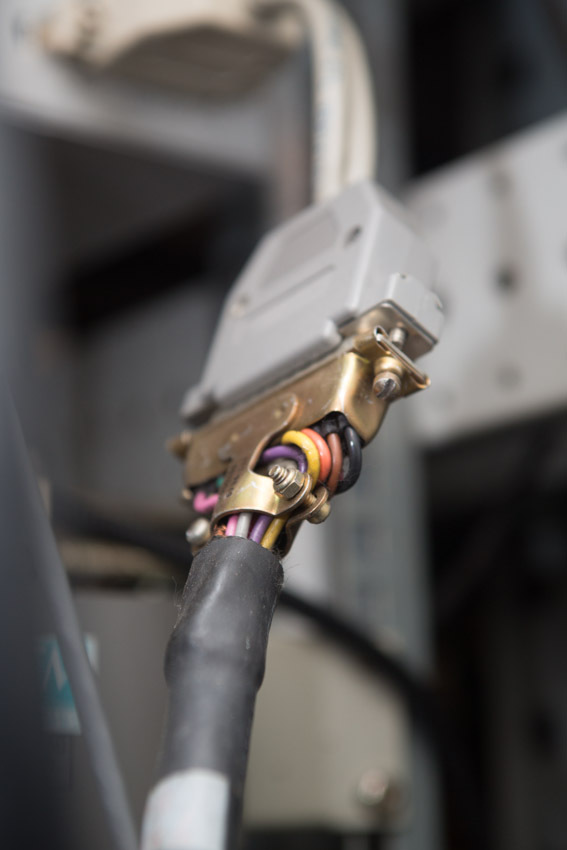
A lot of cables fit the antenna: radio frequency, power, control, control ...
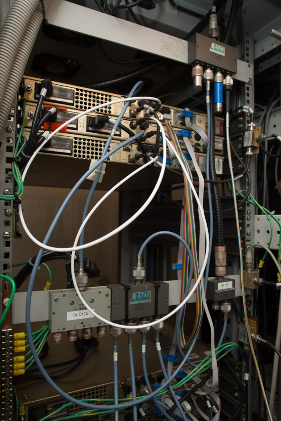
Antenna's “sub-mirror cab” - a view from the inside:
The “pipeline” down is the receiving part, one of the LNA is visible (a rectangular box at the very bottom). Thick cable - output signal from the LNA redundancy switch. "Pipeline" in the middle - the transmission path. A flexible wave guide (left) fits it. And straight ahead, the antenna feed.
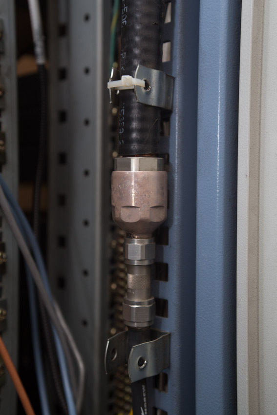
High-frequency cable (top) and "semi-rigid" elliptical waveguide C-band (bottom):
Waveguides are flexible:
Compared with the hard or "semi-rigid" - they have significantly more losses. But the use of flexible waveguides (or sections of flexible highways between two rigid) - increases the simplicity and ease of installation.
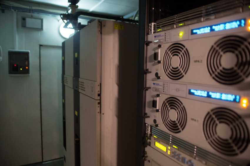
Radio equipment, as well as antenna control systems, are located in containers near the antennas:
Go inside the container
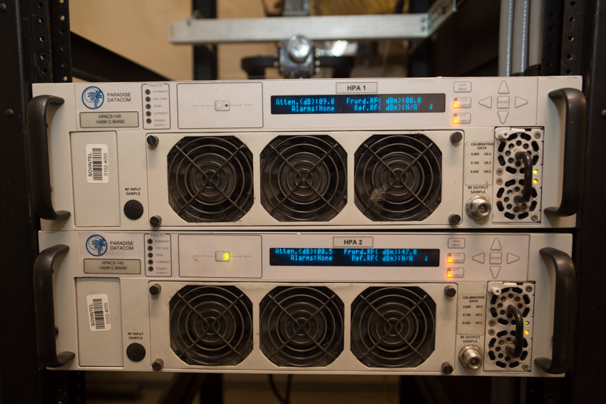
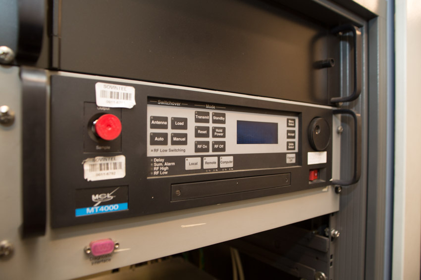
From the entrance we are greeted by “a system of solid state power amplifiers with a 100% reserve. The power amplifier (aka "transmitter") - in fact, allows the antenna to go on the air.
Another transmitter, but no longer a “solid-state” (transistor), but a tube one .
Believe me, it is not installed for the sake of the famous “warm tube sound”! Amplifiers on transistors - just recently began to catch up on their parameters on the amplifiers on the lamps. For example: the transistor at the top - has a maximum power of 140W, and the tube at the bottom - 700W. With the same dimensions and about the same consumption - agree, the difference is very significant. The advantage of transistors is greater linearity. None of the amplifiers work at maximum power, due to the occurrence of nonlinear distortion in it (and this is death for the “phase modulation” used in satellite communications). To obtain a known linear mode, a transistor amplifier can be “overclocked” by no more than half the maximum power. Lamp same - no more than a quarter. But all the same: half of 140W - this is noticeably less than a quarter of 700W.
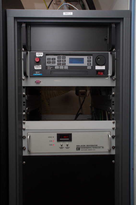
Here is the whole rack:
The gray thing under the transmitter is an air dryer that keeps the waveguide paths in working condition.
And now the rest of the container equipment:
These are the air ducts of the transmitter's cooling system:
Handle on the box see? Also our “know-how”: this is the brand switch of the “winter-summer” modes. It is cold in winter, and the equipment loves room temperature too. Well, yes, you can put a heater, but why? He turned the handle - and warm. And in the spring knob is spinning to another position; and air conditioners together say "thank you, master!"
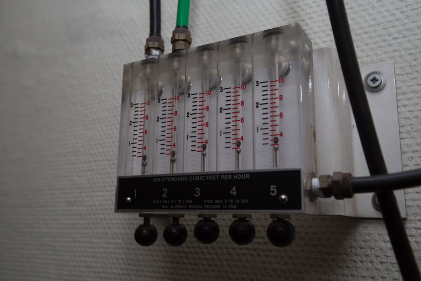
Here is the control unit for the distribution of the waveguide paths. Adjustment of giving - is made by rods with balls (below). Estimate the air flow (and at the same time - the presence of a strong leak) can be on the scales, past which the balls "float":
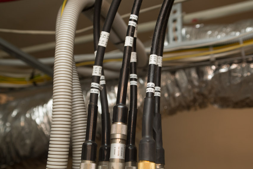
These are the inverter cables coming from the modems in the equipment room, located four floors below. On large nodes - we use the scheme with “PCh70 / 140MHz”, it is simpler and easier than the scheme with “PCh L-Band”. Each pair of cables is the reception and transmission of one transponder.
Stand behind:
And another one:
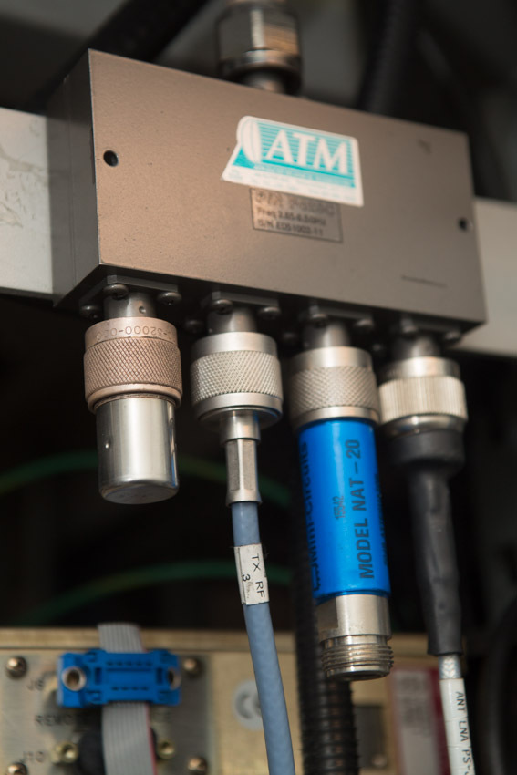
Thick corrugated cable is the input of the receiving signal coming from the low-noise amplifier of the antenna. Why is a low noise amplifier? Theory of radio engineering says: "the noise of the whole system - there can not be less than the noise of its first amplifier stage". To detect a received signal, a certain signal-to-noise ratio is required. And the less self-noise the system adds, the less power will be required from the satellite for the error-free transmission of the same signal.
High-frequency cable from the LNA antenna.
High-frequency cable from the antenna LNA, and high-frequency splitter.
Splitters - share high-frequency signals between converters of different transponders.
One more, but - already for IF signals.
Power cable and control of LNA redundancy system
Two stands away are our first transmitters. Klystronic, C-band, power as much as 3 kW each. I will say right away: at full capacity - they have never worked. But after the next gnawed film - itching very much to turn them on, and to fry a couple of “karkush” on the fly:
Top - switch and waveguides of the backup system; and load for the "spare" transmitter. Load with forced cooling: if the “spare” transmitter operates “in hot standby” (ie it emits exactly the same as the “main” one), all its power is dissipated on the load.
A fan is used for cooling:
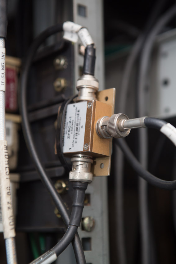
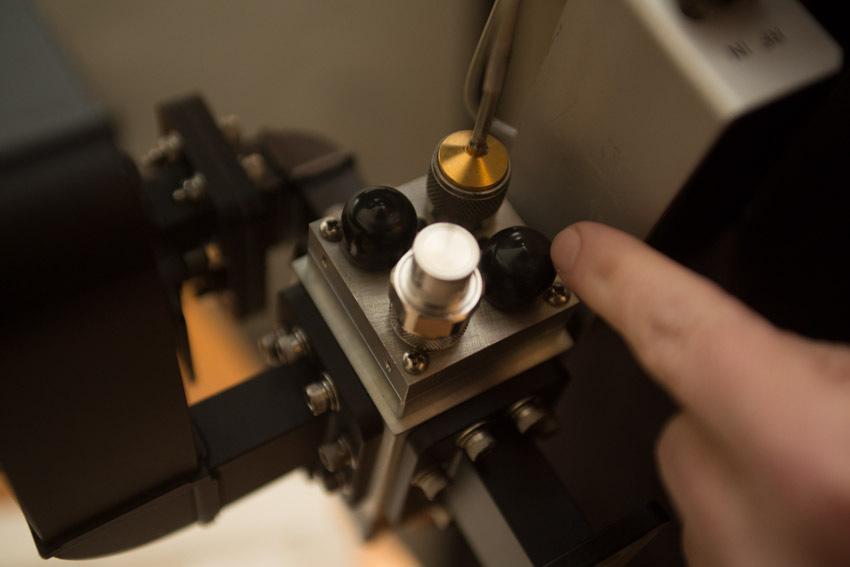
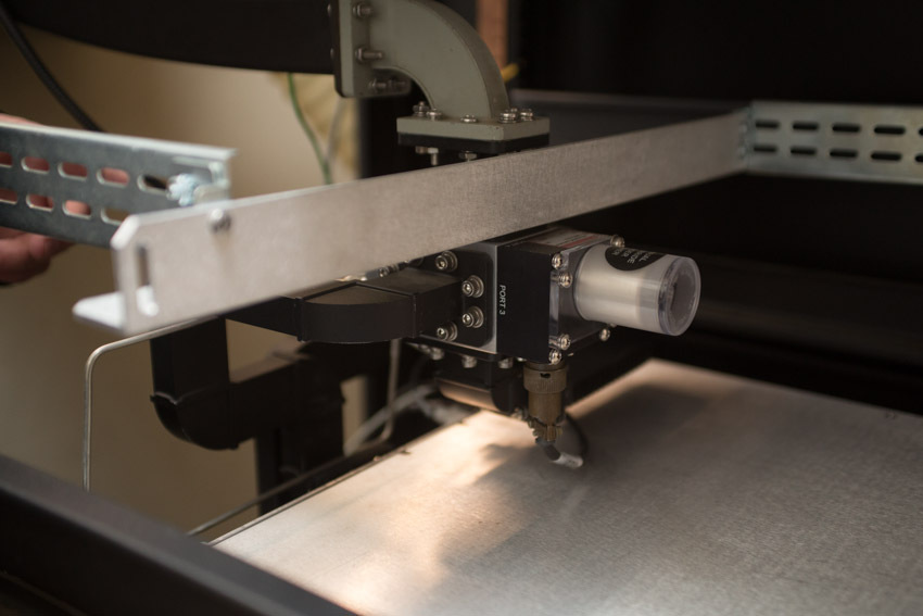
For high-power transistor transmitters - usually used so-called. “Semi-hot” reserve: the “spare” transmitter does not radiate. In this case, a switch is installed in the redundancy system, simultaneously switching both the waveguide output of the transmitter and its coaxial input. It looks like this:
The round little thing on the left is the electric drive for the switch.
Below - the "waveguide" part of the switch, on top - "coaxial". The input of the idle transmitter is connected to the load (silver, in the foreground), which does not allow the transmitter to catch interference from the air.
The connector through which the switch signals are sent to the switch, and from which the backup system receives information about the current position of the switch.
Here is the device in the rack, in operation:
Now back to the roof again, and walk around the antennas:
High-frequency cables (top), “hard” Ku-band waveguides (rectangular in the middle), control and power cables for LNA.
Distribution box on the "foot" of the antenna.
The same, but in a more solid form of "electrical cabinet"
In such boxes and cabinets - plant the power cables of the antenna equipment, auto-tracking system, and antenna anti-icing systems. Well, be sure to - inside there is a very useful thing: a socket for connecting power tools, lighting, etc.
If 220V power is supplied to the antenna, we almost always put similar boxes or shields near the antenna. Additional costs are small, and a lot of amenities during construction and operation.
Now - the next construction.
This is a C-band antenna, so it is so big. Naturally, you should not even try to use such an antenna without an auto-tracking system.
Cable, "twisting" mirror - the power of the anti-icing system (on this antenna - it is made in the form of "heating mats")
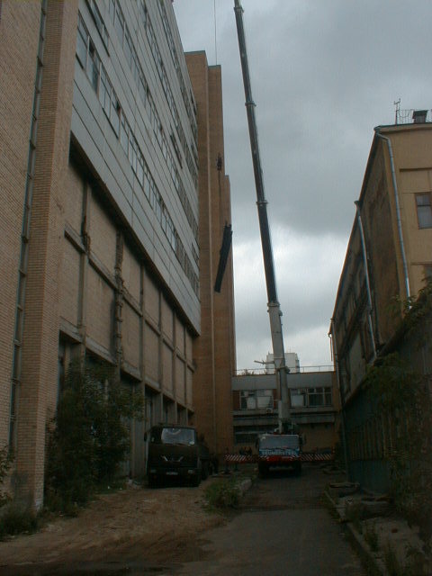
A separate story is associated with the installation. Such antennas are naturally assembled on the ground. In our case, the assembly was carried out here, between these buildings. From the edge of the mirror to the walls was no more than half a meter.
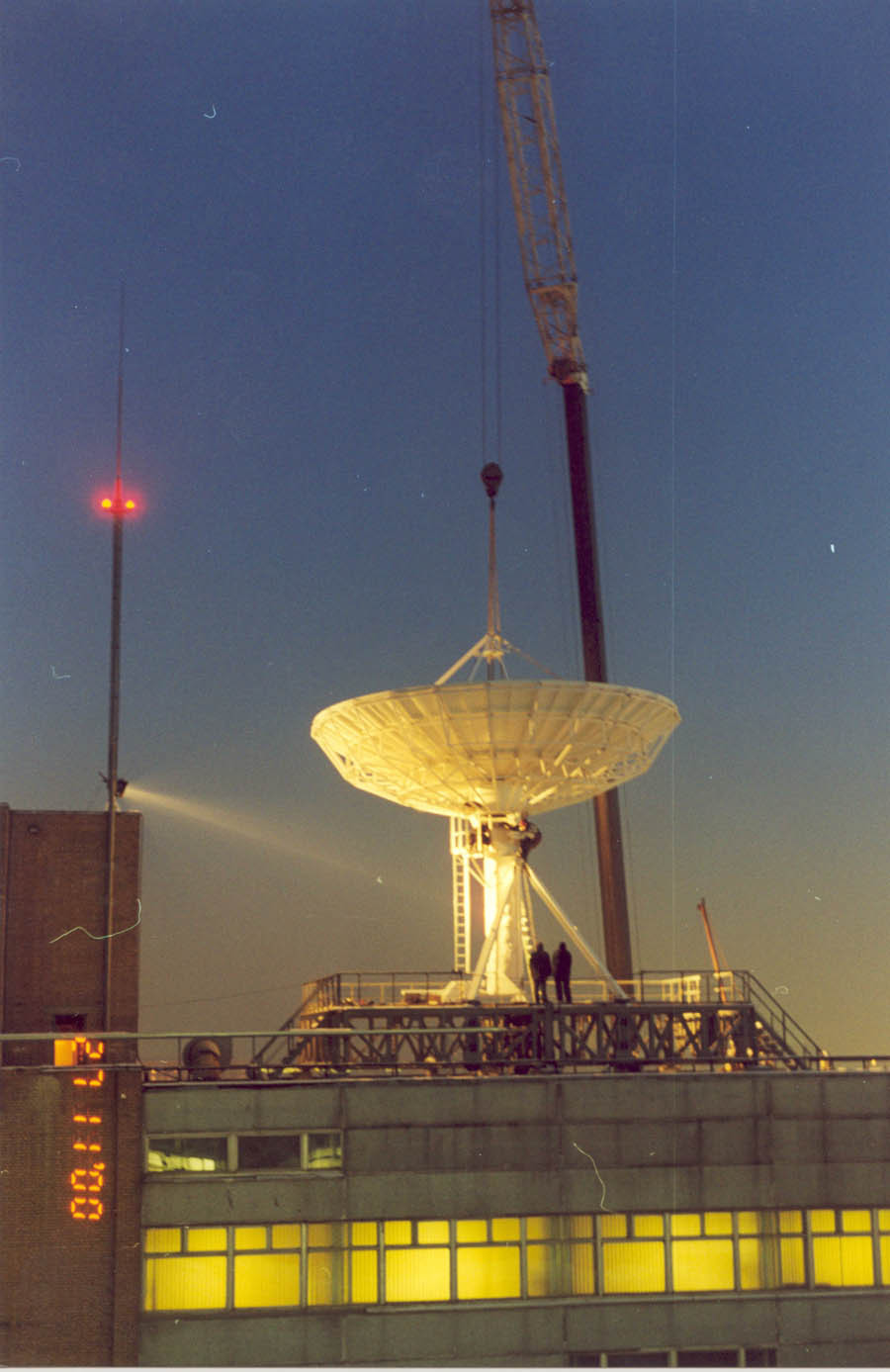
Then it was lifted by a crane. Like this:
Naturally, the crane operator behind the edge of the roof - did not see where to put it, but it was necessary to get on the metal "ears", with a tolerance of a couple of millimeters.
Like this:
The operation was the hardest. And as I have already said, this is almost the only antenna of such diameter in the world, installed not on the ground, but on the roof of a high-rise building.
The irradiator of this antenna. See how his birds gnawed? Yes, it took them almost 15 years to do this; but I say: the crow's beaks are armor-piercing.
And there is a faint edge over there. It was either the crows got to the film again, or the remnant of the previous radio transparent film. I'd like to believe in the latter; However, after a couple of days, you will need to carry out maintenance work. And here it is also interesting. Serving such an antenna, and in particular its feed, is not an easy task. Ahead - the abyss of 12 floors, remember? You can, of course, turn the antenna sideways, towards the roof. But the fact is that the auto maintenance drive does not allow you to quickly move the antenna. Rotate 90 degrees - will take several hours; And the drive for such essential turns is not intended.
Therefore - we had to reinvent a little again.
"Regular" drive - disconnects:
Instead, he put homemade temporary: small, but very fast. He turns the antenna to the desired angle in just five minutes.
To prevent the antenna from winding down with an occasional gust of wind, at the time of disconnecting the main drive, and at a time when the entire antenna is held on “self-made fast” - the antenna column is fixed to the “temporary anchor”:
In the eye above - one of the “ears” of the antenna enters, to which a regular drive clings. The whole structure is fixed with a finger (hanging at the bottom of the eyelet). All wind gusts are no longer scary to us.
On the side of the antenna, we made a special "tilting" area.
We turn off the transmitters, turn the antenna to the site with an additional drive, “tilt” the site into the mirror - and now the irradiator is easily accessible for any work, repair and maintenance. Simple, reliable, convenient and safe!
Small FAQ
- Why do you need such a large and expensive object?
That communication was also where there are no land lines of communication. Or they are, but small capacity, poor quality, or very expensive.But there are still many such places in Russia: even large cities like Petropavlovsk-Kamchatsky, Magadan, Anadyr, Norilsk - do not have land channels (of sufficient capacity). What to speak about the villages in Yakutia or in the Far East, or about the gas production complexes in Siberia. And this is not only for cellular communication: ipvpn or Lan2Lan is very popular among the same drillers; first of all for monitoring such complex objects as drilling. And you can talk via Skype ... Yes, satellite channels can not be compared with optics in terms of bandwidth: a satellite channel with a speed of 10 Mbps is considered very wide. Can I do more? It is possible, we have channels both 100 and 200 Mbit each. But this, above all, is a very expensive pleasure.
- At each base station put on FSS?
Not necessary.If there is a group of BSs that are interconnected by terrestrial channels, then for the operation of the whole group, a single JSSS is sufficient; how this is done, for example, here in Bovanenkovo (http://habrahabr.ru/company/beeline/blog/247773/).
But sometimes it is easier and cheaper to build two ZSSS, than to try to lay a landline between two points. For example, Keperway Airport is, according to Wikipedia, only 32km from Bilibino. But to stretch the channel from there to Bilibino is almost impossible, and therefore we have another ZSSS there.
- How does satellite communication work?
A satellite is a kind of mirror that looks at a certain territory: the so-called. "Service area". And in principle, any two stations located within this territory can communicate with each other. Actually, this is the main beauty of satellite communications: distances are not important to it. The correspondent station may be located on the neighboring house, or maybe thousands of kilometers from the “center”; for satellite communications - it makes no difference.
Transmitting station - broadcasts the signal to the satellite. The host picks it up, decodes it, and transmits the received data towards the user. If the communication system is bidirectional (and not broadcast, as, for example, “satellite TV”), then in the opposite direction, everything works the same way.
The most typical scheme for building satellite networks is the so-called. "Star": many small stations in the district, and "center" with a large antenna in the middle. But there are also communication systems capable of working on the principle of “everyone with everyone”.
From the point of view of the organization of satellite channels - they can all be divided into two types: systems with "fixed channels", and "systems with the provision of a channel on demand." The former are commonly used on trunk links, the latter are used on circuits with low or very irregular traffic. And the main criterion here is not the type of traffic or its consumer, but the nature of the traffic. The same BS: if the BS is located in a large village, then it is usually connected via a “fixed channel”. If the BS is installed in the village, where only about a dozen people, then it makes sense to use the system "provide channels on demand."
- What does it consist of and how does the ZSSS work?
All satellite communication stations have a similar device, and consist of almost the same functional components.
"The reception path." The satellite signal received by the antenna enters the antenna feed. There are three devices in the illuminator: a polarization selector, a diplexer and filters. The polarization selector selects the polarization we need, the diplexer separates the transmit and receive signals, the filters cut all unnecessary (in the receive path the transmit frequencies and vice versa).
The filtered signal - comes to the low-noise amplifier. The parameters of which, as we recall, actually determine the quality of the work of the entire receiving system as a whole.
From the output of the LNA, the signal goes to the “down converter”, where it is transferred from “high frequency” (4 GHz for the C band, and 11 GHz for the Ku band) - to a lower “intermediate frequency”. Depending on the scheme of a specific ZSSS - it may be different. Several steps of conversion can also be used - it all depends on what needs to be done and how it can be done most conveniently and efficiently.
Next, the signal enters the demodulator, which converts the analog terrestrial signal into a digital stream.
Since the satellite channel operates at very low signal-to-noise ratios, the probability of error in the received stream (channel) does not exceed 1E-3. If such a channel is immediately sent directly to the end user, then nothing will work. Therefore, on any satellite channels - powerful noise-resistant coding is used; and the next required link is a decoder. The decoder corrects errors, and the stream received already “almost error-free” (with an error probability no worse than 1–8) sends it through a standard interface to the terminal data equipment. That's all you want: a computer, a packet switch, a BS ...
"Transmission path". All the same, only in the opposite direction. The signal from the data terminal equipment - through the standard interface goes to the encoder. The coder imposes on the incoming data - a certain amount of “redundant information”, which then will allow the decoder to correct errors that have occurred in the channel. The resulting stream gets to the modulator, which turns the digital stream into an analog signal.
Then this signal goes to the “up converter”, from it to the power amplifier. The amplified signal through the diplexer and the polarization selector enters the antenna feed. And from there to the sky, to the satellite.
Each “function block” is not necessarily a separate element or device. One unit can perform several functions. For example, “LNA + Converter Down” is a so-called. “Low Noise Converter” (LNC), “Converter Up + Power Amplifier” is a “block-upconverter” (BUC), “demodulator + modulator + codec + interface” is a “modem”. Up to the point that all the devices shown in the figure can be combined within one small case, as in the “satellite phones” of the Iridium or Thuraya systems.
Depending on the purpose of a specific ZSSS, there may be many similar functional devices on it: modems, converters, amplifiers. If the SCSS is used only for reception, then the entire lower part of the picture, related to the transmission path, is completely absent in it.
About the roof, antennas and radio equipment - for now. Then, according to the tour plan, find out where the IF cables go and what the modems look like. This and a little work with the oscilloscope will be in the second part, if you are interested, and then the post already and so it will turn out to be very heavy.
Source: https://habr.com/ru/post/253841/
All Articles