Building an Ethernet network for IP video surveillance
Market interest in IP cameras is quite understandable. They have many advantages: a wide choice of devices, flexibility of software functionality, a good picture, easy integration into the computer infrastructure. It is time to think about how it is most convenient and economical to build a stable data transmission environment for scalable video-based IP cameras. Just throwing the optics and connecting to it the first set of media converters that came across and unpretentious hubs is also a way out, but fraught with many problems in the future. It makes sense to investigate the problem more deeply.
There are a lot of questions. What is the wiring diagram? Before laying the cable, the question arises: how to lay? What cable to put? How many fibers should there be? And what, it is also necessary to cook it? What active equipment to use? ... Etc.
Let's look at all these questions in order, using the example of an abstract territory.
In fig. №1 given the scheme of such a territory.
')
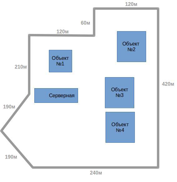
Pic1
The layout, the choice of the type and the required number of cameras, we omit their direction, since these questions require a separate article. The perimeter of our territory is about 1550 meters. Suppose that 15 IP cameras located within a radius of 100 meters from the cabinets will suffice for video surveillance. This distance is due to the fact that the Ethernet standard regulates the operating state of a segment with a length of no more than 100 meters. Currently, the de facto standard is the use of POE technology, which allows powering the camera from the switch over the same UTP cable it is connected to. This solves a lot of problems associated with the supply of electricity, since in this case it is enough to power the control cabinet with the switch, and you can no longer take care of the power supply of the camera.
Thus, we get from 2 (in the diagram: a circle labeled “2k”) to 3 (in the diagram: a circle labeled “3k”) cameras per cabinet.
It would be reasonable to combine these cabinets with a server optical cable using 2 directions (shown in the diagram in red and blue). In Figure 2, both cable directions, cabinets, and the “possible” position of Cabinet No. 7 are added, which we, for example, were not going to be assembled at this stage, but we want this opportunity to be in the future.
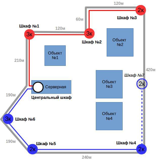
Pic2
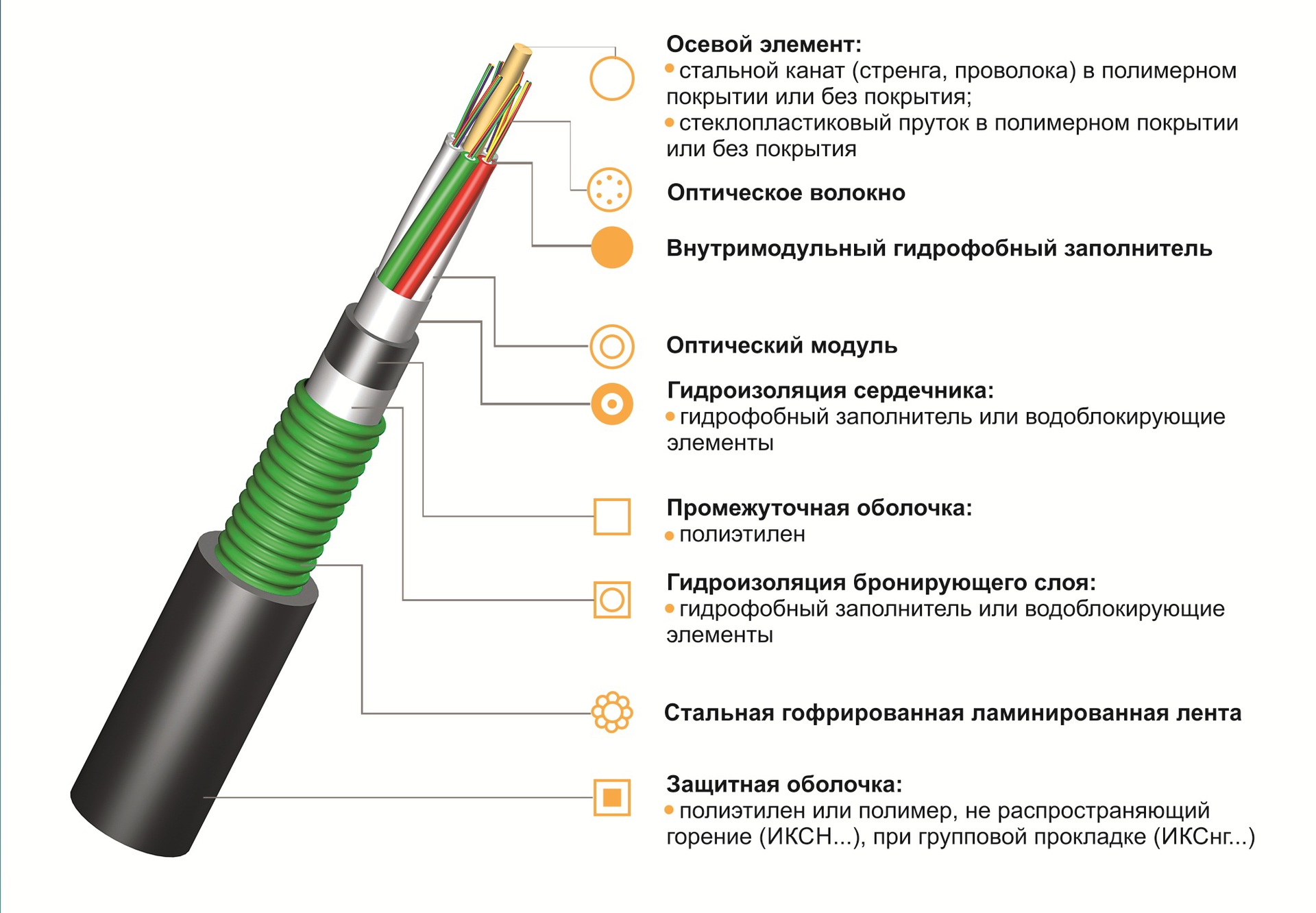
Now the question arises: what cable design to use? The answer to this question depends largely on the method of installation. For example, if there are pillars along the territory perimeter, then it is more reasonable to use a “suspension cable with a portable power element”. The design of this cable is shown in Fig. 3

Pic.3
Using the nomenclature of one of the major suppliers of optical cable, Integra, the model of such a cable will be called IR / T-M4P-Ax. The last 2 characters mean: “A” is a single-mode cable, and the number of fibers is put in place of the “x”. For example, "A8" is 8 single-mode fibers.
If you plan to lay the cable in the ground, or mount along the fence, it is wiser to choose a design with light armor. See fig. four
Pic.4
According to the same nomenclature of the Integra company, the model will be called ICL-M4P-Ah.
In real projects, combinations of these as well as the use of other structures are possible, but the cables described above are used most often.
The type of cable was chosen, but now the question arises, how to combine it all at the level of optical fibers, or in other words: “How are we going to cook, customer?”
Here it is worth considering all three possible scenarios. In short, to put it all together:
- consistently "bus";
- star using individual fibers / fiber on the optical connection.
At this stage it is necessary to build the so-called “welding plan”. Why is it needed? Well, first of all, you, as a customer, will have in front of you a detailed wiring diagram, which later will come in handy during the operation. Secondly, inviting an engineer-welder from the side, or giving tasks to his specialist, there is no other way to clearly and clearly set the task. And, thirdly, on this scheme all 3 variants of the connections will be visible, which we will now consider.
Pic.5
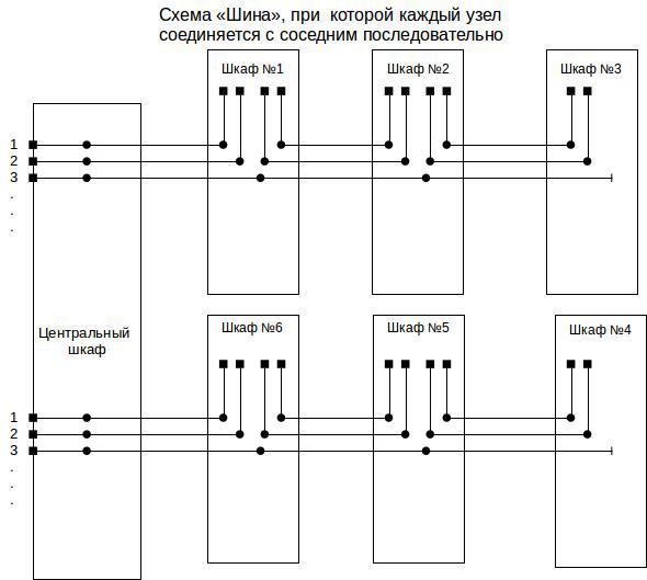
So, option number 1: consistently "bus", is given in Fig. №5. The black dots on this diagram indicate the places of welding, the black squares indicate the connectors, and the lines ending with a small dash are loosely left fibers.
As can be seen from the diagram, only 2 fibers will be involved in the cable, including when adding a new cabinet. In case there are more than 2 fibers in the cable, during the installation stage it is recommended to weld free fibers, as shown in the example of the 3rd fiber. This will be done in any case is useful, because in case of further development of the network will not need to climb into the already mounted cabinets, increasing the risk of emergency situations.
When using this scheme, we see that for the installation we will need 2 or more fiber optic cable, and the equipment is required to have at least 2 optical ports.
This scheme, although attractive for its simplicity, obviousness and fewer welds, however, it has one major drawback. Imagine that something happened to the equipment in the cabinet №1. What will happen to our connections in cabinets №2 and №3? Right! We will lose them.
To avoid such cases, it is necessary to continue the cable from cabinet No. 4 and return it (preferably by other means, for example by connecting to cabinet No. 5) to the server room, thus creating a ring. In this case, of course, the support of the “ring” by active equipment, and its correct configuration, is required. And obviously, this will require an additional 420 meters of cable and managed switches, which are not cheap.
It should be mentioned that in the scheme under consideration it is possible to use just one fiber if we use optical equipment WDM, which allows to transmit and receive a signal using 1 fiber at different wavelengths. However, this does not solve the problem described above.
An alternative to this connection scheme would be the use of the “Star” topology shown in Fig. 6

Pic.6
As can be seen from this scheme, when using this topology, each cabinet will be connected “independently” from its neighbors. Why is the word “independent” quoted? It should be understood that, of course, we will lose connections in cabinets No. 2 and No. 3, if we cut, for example, the cable between the server and cabinet No. 1. From such a trouble will save only the construction of this ring, as described above. However, it definitely saves from problems with power supply or equipment failure inside the cabinet №1.
The diagram shows that the number of welds is increasing, because, if you do not use the "transit" installation, then you need to weld each pair of fibers passing through the adjacent cabinet. Of course, as in the previous version, WDM transceivers can be used, which in turn reduces the number of fibers used in two, and the number of welds.
What scheme to choose - decides the customer.
Since it is desirable for us to ensure the independent functioning of each cabinet from each other and to use inexpensive equipment, in this example we will take as a basis the star connection scheme, in which there are 2 separate fibers going from the server to each cabinet.
Virtually with the scheme, we decided, but how will it look in practice? Usually, to minimize losses on the one hand, and reliable termination on the other, it is possible to use an optical box model GP-B for fiber termination inside cabinets. Its appearance is shown in Fig. 7

Fig.7
The box has two ports for the cable (input and output in our case) and a mount for the outgoing optical cord. A feature of this box is that the fibers to be terminated are welded directly to the halves of the patch cords, and the transit fibers are welded into a splice cassette. Thus, the connection is simplified (the bundle welding + pigtail + adapter + patchcord is removed), thereby reducing losses. In our case, we will use 1.5 meter halves of the 3 meter patchcord LC / UPC-LC / UPC-SMB1-DX-3M. The question of using the connector LC / UPC, we touch on a little later.
In this regard, I note that some customers who want to “save” at a loss are limited only to the splice cassette and welding of the pigtail (0.9 mm in diameter), which ultimately leads to breaks and other troubles.
This solution will reliably fix both ends of the optical cable, protect the welding points and provide an opportunity to connect the equipment using a 3mm-protected cord.
In the server, the question of cable termination is somewhat different. Since the server room is often equipped with a 19 inch cabinet, in this case it is necessary to use an optical cross. In our case, we need an optical cross, complete with 16 optical ports. A good choice would be the model FODF-1U-24SCSX / 24LCDX, shown in fig. eight.
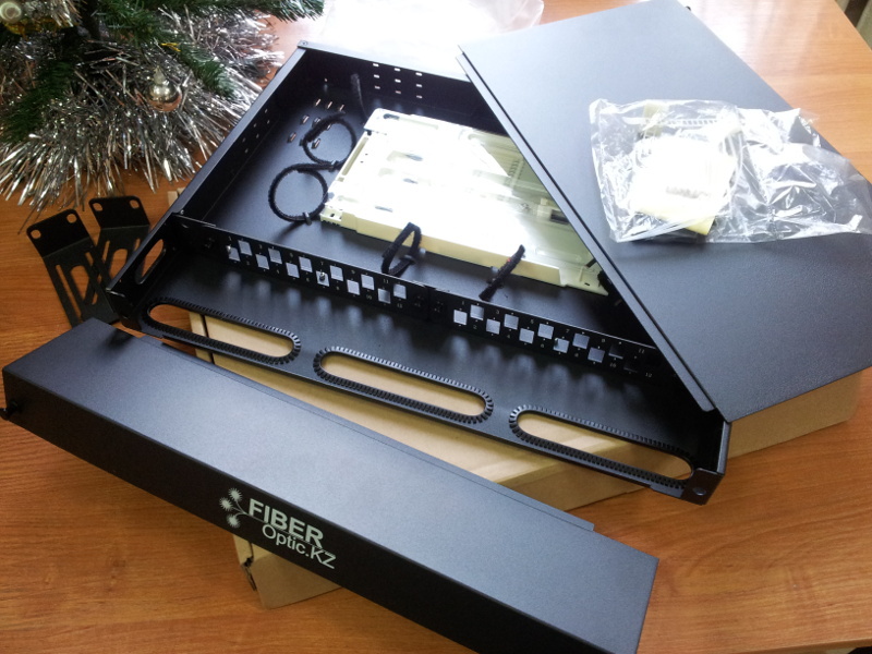
Fig.8
This model has a lightweight aluminum body, 3 interchangeable straps, designed for adapters either SC simplex or LC duplex, and a capacious splice cassette. Practically, this is all we need.
In the future, of course, we will need optical patch cords, for example SC / UPC-LC / UPC-SMB1-DX-1M, which are perfect for connecting our equipment to this cross-country.
Now it is time to decide on active equipment. Of course, the task can be solved with the use of office switches, soap cases and media converters, thus creating a unique heap of equipment that inspires horror to the servicing engineers. Perhaps the reader has already heard, or even used so-called “industrial” switches (similar to MOXA, Hirschmann, etc.). However, a solution based on them can be quite expensive. What is the best way to do and choose moderately inexpensive equipment that would solve our problems? Such equipment exists! For example, take two models of unmanaged switches with POE ports FastEthernet and SFP port. Below in Fig.10 are given 2 models in 4 and 8 ports respectively:
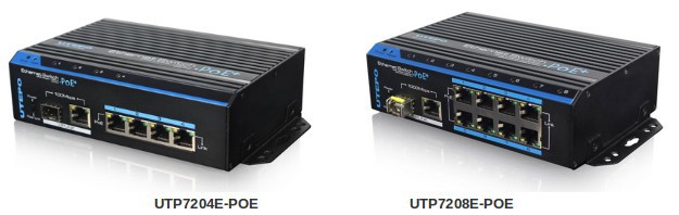
Fig.9
As you can see, we are dealing with switches in the “industrial” form factor, which makes it possible to mount these models on a DIN rail and work effectively in adverse conditions.
This model belongs to the class of unmanaged switches, which in turn has a positive effect on its price. In our scheme, we can choose the model UTP7204E-POE, with four copper POE ports and one SFP port.
Let's make it clear: where do we connect the optics? And we will connect the optics to the SFP module, which, in turn, will be inserted into the SFP switch port. Why do we need such difficulties, you ask? And we will answer - the use of various optical modules makes it possible to use this switch in 2 fiber circuits, in 1 fiber circuits, on multimode fiber, and at different distances, etc. in one word. , pick up the optical module you need, insert it into the switch, and you're done!
In our case, we will choose an inexpensive optical module model APS31123xxL2 shown in Figure 10.
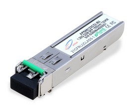
Pic.10
This gigabit module working on 2 fibers will allow us to make connections up to 2 km away!
Well, in the cabinets we will use 4-port switches, and what can be used in the server?
In the server room, in order to collect all the optical links, we will need a more serious switch. So, the UTP7524GE-MX model is a Gigabit modular (which is very important) managed switch. Its appearance is shown in Fig. eleven
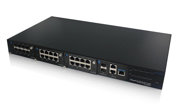
Fig. eleven
Modular it is named because it allows, in the process of growth of the network itself, to use additional modules for connecting optical links. In total, there are up to 3 such modules, i.e., 8 ports, 16 ports, and finally, 24 ports!
Since in our case we need 6 ports to connect with 6 cabinets, then one module (see fig.12) will be quite enough for a start.

Fig.12
And, of course, to him we will need the same optical modules that we used in the cabinets.
There was one question I promised to answer: why is the LC / UPC connector? Just because, as you have noticed, this connector is most often used in optical SFP modules.
There are a lot of questions. What is the wiring diagram? Before laying the cable, the question arises: how to lay? What cable to put? How many fibers should there be? And what, it is also necessary to cook it? What active equipment to use? ... Etc.
Let's look at all these questions in order, using the example of an abstract territory.
In fig. №1 given the scheme of such a territory.
')
Pic1
The layout, the choice of the type and the required number of cameras, we omit their direction, since these questions require a separate article. The perimeter of our territory is about 1550 meters. Suppose that 15 IP cameras located within a radius of 100 meters from the cabinets will suffice for video surveillance. This distance is due to the fact that the Ethernet standard regulates the operating state of a segment with a length of no more than 100 meters. Currently, the de facto standard is the use of POE technology, which allows powering the camera from the switch over the same UTP cable it is connected to. This solves a lot of problems associated with the supply of electricity, since in this case it is enough to power the control cabinet with the switch, and you can no longer take care of the power supply of the camera.
Thus, we get from 2 (in the diagram: a circle labeled “2k”) to 3 (in the diagram: a circle labeled “3k”) cameras per cabinet.
It would be reasonable to combine these cabinets with a server optical cable using 2 directions (shown in the diagram in red and blue). In Figure 2, both cable directions, cabinets, and the “possible” position of Cabinet No. 7 are added, which we, for example, were not going to be assembled at this stage, but we want this opportunity to be in the future.
Pic2
Now the question arises: what cable design to use? The answer to this question depends largely on the method of installation. For example, if there are pillars along the territory perimeter, then it is more reasonable to use a “suspension cable with a portable power element”. The design of this cable is shown in Fig. 3
Pic.3
Using the nomenclature of one of the major suppliers of optical cable, Integra, the model of such a cable will be called IR / T-M4P-Ax. The last 2 characters mean: “A” is a single-mode cable, and the number of fibers is put in place of the “x”. For example, "A8" is 8 single-mode fibers.
If you plan to lay the cable in the ground, or mount along the fence, it is wiser to choose a design with light armor. See fig. four
Pic.4
According to the same nomenclature of the Integra company, the model will be called ICL-M4P-Ah.
In real projects, combinations of these as well as the use of other structures are possible, but the cables described above are used most often.
The type of cable was chosen, but now the question arises, how to combine it all at the level of optical fibers, or in other words: “How are we going to cook, customer?”
Here it is worth considering all three possible scenarios. In short, to put it all together:
- consistently "bus";
- star using individual fibers / fiber on the optical connection.
At this stage it is necessary to build the so-called “welding plan”. Why is it needed? Well, first of all, you, as a customer, will have in front of you a detailed wiring diagram, which later will come in handy during the operation. Secondly, inviting an engineer-welder from the side, or giving tasks to his specialist, there is no other way to clearly and clearly set the task. And, thirdly, on this scheme all 3 variants of the connections will be visible, which we will now consider.
Pic.5
So, option number 1: consistently "bus", is given in Fig. №5. The black dots on this diagram indicate the places of welding, the black squares indicate the connectors, and the lines ending with a small dash are loosely left fibers.
As can be seen from the diagram, only 2 fibers will be involved in the cable, including when adding a new cabinet. In case there are more than 2 fibers in the cable, during the installation stage it is recommended to weld free fibers, as shown in the example of the 3rd fiber. This will be done in any case is useful, because in case of further development of the network will not need to climb into the already mounted cabinets, increasing the risk of emergency situations.
When using this scheme, we see that for the installation we will need 2 or more fiber optic cable, and the equipment is required to have at least 2 optical ports.
This scheme, although attractive for its simplicity, obviousness and fewer welds, however, it has one major drawback. Imagine that something happened to the equipment in the cabinet №1. What will happen to our connections in cabinets №2 and №3? Right! We will lose them.
To avoid such cases, it is necessary to continue the cable from cabinet No. 4 and return it (preferably by other means, for example by connecting to cabinet No. 5) to the server room, thus creating a ring. In this case, of course, the support of the “ring” by active equipment, and its correct configuration, is required. And obviously, this will require an additional 420 meters of cable and managed switches, which are not cheap.
It should be mentioned that in the scheme under consideration it is possible to use just one fiber if we use optical equipment WDM, which allows to transmit and receive a signal using 1 fiber at different wavelengths. However, this does not solve the problem described above.
An alternative to this connection scheme would be the use of the “Star” topology shown in Fig. 6
Pic.6
As can be seen from this scheme, when using this topology, each cabinet will be connected “independently” from its neighbors. Why is the word “independent” quoted? It should be understood that, of course, we will lose connections in cabinets No. 2 and No. 3, if we cut, for example, the cable between the server and cabinet No. 1. From such a trouble will save only the construction of this ring, as described above. However, it definitely saves from problems with power supply or equipment failure inside the cabinet №1.
The diagram shows that the number of welds is increasing, because, if you do not use the "transit" installation, then you need to weld each pair of fibers passing through the adjacent cabinet. Of course, as in the previous version, WDM transceivers can be used, which in turn reduces the number of fibers used in two, and the number of welds.
What scheme to choose - decides the customer.
Since it is desirable for us to ensure the independent functioning of each cabinet from each other and to use inexpensive equipment, in this example we will take as a basis the star connection scheme, in which there are 2 separate fibers going from the server to each cabinet.
Virtually with the scheme, we decided, but how will it look in practice? Usually, to minimize losses on the one hand, and reliable termination on the other, it is possible to use an optical box model GP-B for fiber termination inside cabinets. Its appearance is shown in Fig. 7
Fig.7
The box has two ports for the cable (input and output in our case) and a mount for the outgoing optical cord. A feature of this box is that the fibers to be terminated are welded directly to the halves of the patch cords, and the transit fibers are welded into a splice cassette. Thus, the connection is simplified (the bundle welding + pigtail + adapter + patchcord is removed), thereby reducing losses. In our case, we will use 1.5 meter halves of the 3 meter patchcord LC / UPC-LC / UPC-SMB1-DX-3M. The question of using the connector LC / UPC, we touch on a little later.
In this regard, I note that some customers who want to “save” at a loss are limited only to the splice cassette and welding of the pigtail (0.9 mm in diameter), which ultimately leads to breaks and other troubles.
This solution will reliably fix both ends of the optical cable, protect the welding points and provide an opportunity to connect the equipment using a 3mm-protected cord.
In the server, the question of cable termination is somewhat different. Since the server room is often equipped with a 19 inch cabinet, in this case it is necessary to use an optical cross. In our case, we need an optical cross, complete with 16 optical ports. A good choice would be the model FODF-1U-24SCSX / 24LCDX, shown in fig. eight.
Fig.8
This model has a lightweight aluminum body, 3 interchangeable straps, designed for adapters either SC simplex or LC duplex, and a capacious splice cassette. Practically, this is all we need.
In the future, of course, we will need optical patch cords, for example SC / UPC-LC / UPC-SMB1-DX-1M, which are perfect for connecting our equipment to this cross-country.
Now it is time to decide on active equipment. Of course, the task can be solved with the use of office switches, soap cases and media converters, thus creating a unique heap of equipment that inspires horror to the servicing engineers. Perhaps the reader has already heard, or even used so-called “industrial” switches (similar to MOXA, Hirschmann, etc.). However, a solution based on them can be quite expensive. What is the best way to do and choose moderately inexpensive equipment that would solve our problems? Such equipment exists! For example, take two models of unmanaged switches with POE ports FastEthernet and SFP port. Below in Fig.10 are given 2 models in 4 and 8 ports respectively:
Fig.9
As you can see, we are dealing with switches in the “industrial” form factor, which makes it possible to mount these models on a DIN rail and work effectively in adverse conditions.
This model belongs to the class of unmanaged switches, which in turn has a positive effect on its price. In our scheme, we can choose the model UTP7204E-POE, with four copper POE ports and one SFP port.
Let's make it clear: where do we connect the optics? And we will connect the optics to the SFP module, which, in turn, will be inserted into the SFP switch port. Why do we need such difficulties, you ask? And we will answer - the use of various optical modules makes it possible to use this switch in 2 fiber circuits, in 1 fiber circuits, on multimode fiber, and at different distances, etc. in one word. , pick up the optical module you need, insert it into the switch, and you're done!
In our case, we will choose an inexpensive optical module model APS31123xxL2 shown in Figure 10.
Pic.10
This gigabit module working on 2 fibers will allow us to make connections up to 2 km away!
Well, in the cabinets we will use 4-port switches, and what can be used in the server?
In the server room, in order to collect all the optical links, we will need a more serious switch. So, the UTP7524GE-MX model is a Gigabit modular (which is very important) managed switch. Its appearance is shown in Fig. eleven
Fig. eleven
Modular it is named because it allows, in the process of growth of the network itself, to use additional modules for connecting optical links. In total, there are up to 3 such modules, i.e., 8 ports, 16 ports, and finally, 24 ports!
Since in our case we need 6 ports to connect with 6 cabinets, then one module (see fig.12) will be quite enough for a start.
Fig.12
And, of course, to him we will need the same optical modules that we used in the cabinets.
There was one question I promised to answer: why is the LC / UPC connector? Just because, as you have noticed, this connector is most often used in optical SFP modules.
Source: https://habr.com/ru/post/253373/
All Articles