The history of participation in the competition "Flying robots". Part 1
Foreword
In 2013, in order to popularize robotics in Russia and create an environment for programmers and engineers focused on this topic, CROC (Moscow) organized the Flying Robots competition. Our team “iKar” (3 people from Barnaul and 1 from Moscow) participated in 2013 (the “Fly and Return” competition) and 2014 (“Catch up and overtake Krok”) did not win, but achieved quite good results.
1. How it all began or the conditions of the competition
Being a profession programmer 1C, often have to use the forum forum.mista.ru. One of my friends, colleagues, was the first to notice an ad on “Who is Lemon,” and offered to participate.
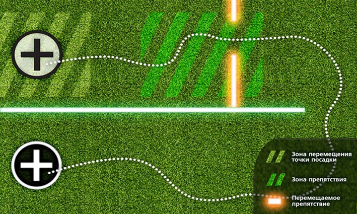
The conditions of the competition looked tempting: it was necessary to build or buy a flying robot and teach it to move / orient around the training area, automatically take off and land, and recognize the landing markers. The term for the whole work is 1 year, and the prize is 1 million rubles.
')
There was experience in building helicopters and quadcopters, both for hobbies and for professional use in aerial photography. There were many questions about the various settings, PID coefficients, code and algorithms of flight controllers. Using the motivation of the competition, it was possible to understand everything deeply.
Since childhood, the dream was to engage in robotics, participation in the competition allowed us to take the first steps in this direction. Belief in one's own forces, a “right” business and a “tasty” prize, did their job, the whole family budget plus the available credit funds were used to build a “budget” drone robot and go to Moscow for a competition.
2. Choosing an aircraft platform
 As an aircraft (LA) you could use:
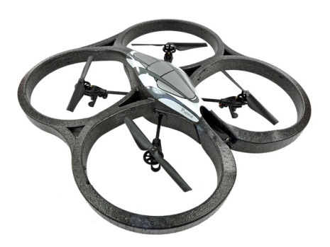
1) a finished drone, for example, “AR.Drone”, already able to fly and many buns, of the minuses:
- low iron productivity;
- low payload.
2) Build your own aircraft of the desired capacity and with the required flight time.
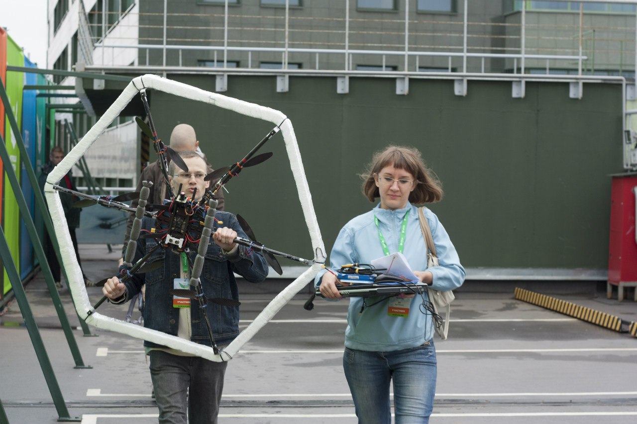
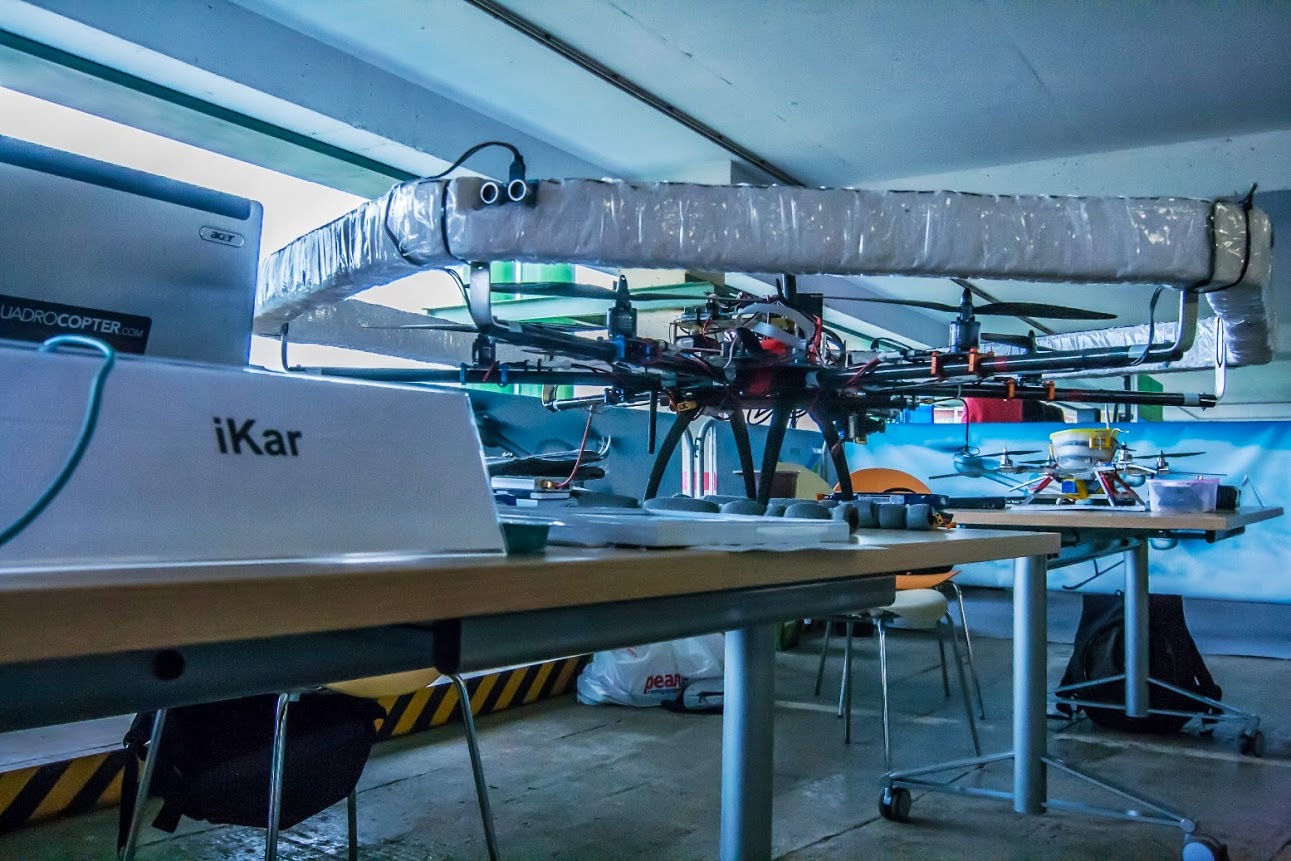
The second point did not cause doubts, a hexakopter (6 motor kopter) with an estimated carrying capacity of 2 kg and an estimated time of 20 minutes with a load from the camera and the necessary electronics was an excellent option. For the tests, it was decided to make a small quadrocopter - “whipping boy”.
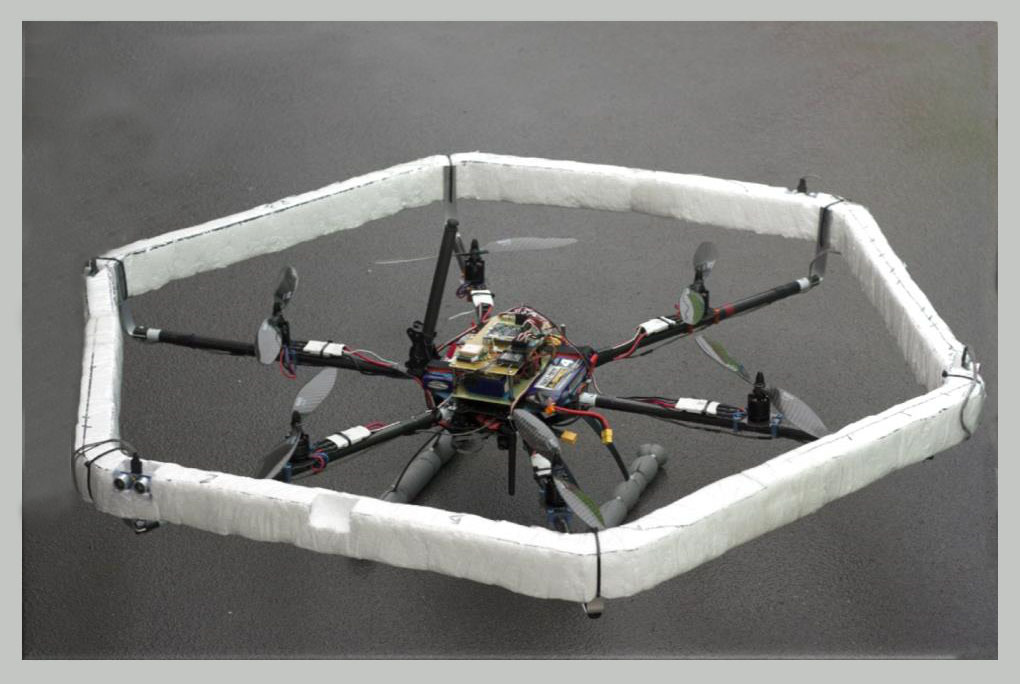
Geksakopter on the basis of the frame Tarot-680

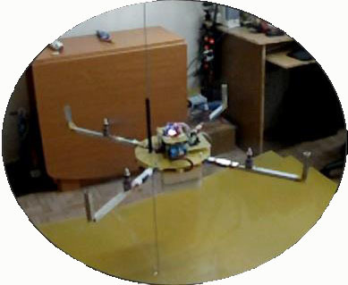
Quadcopter for "whipping"
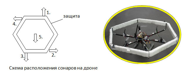
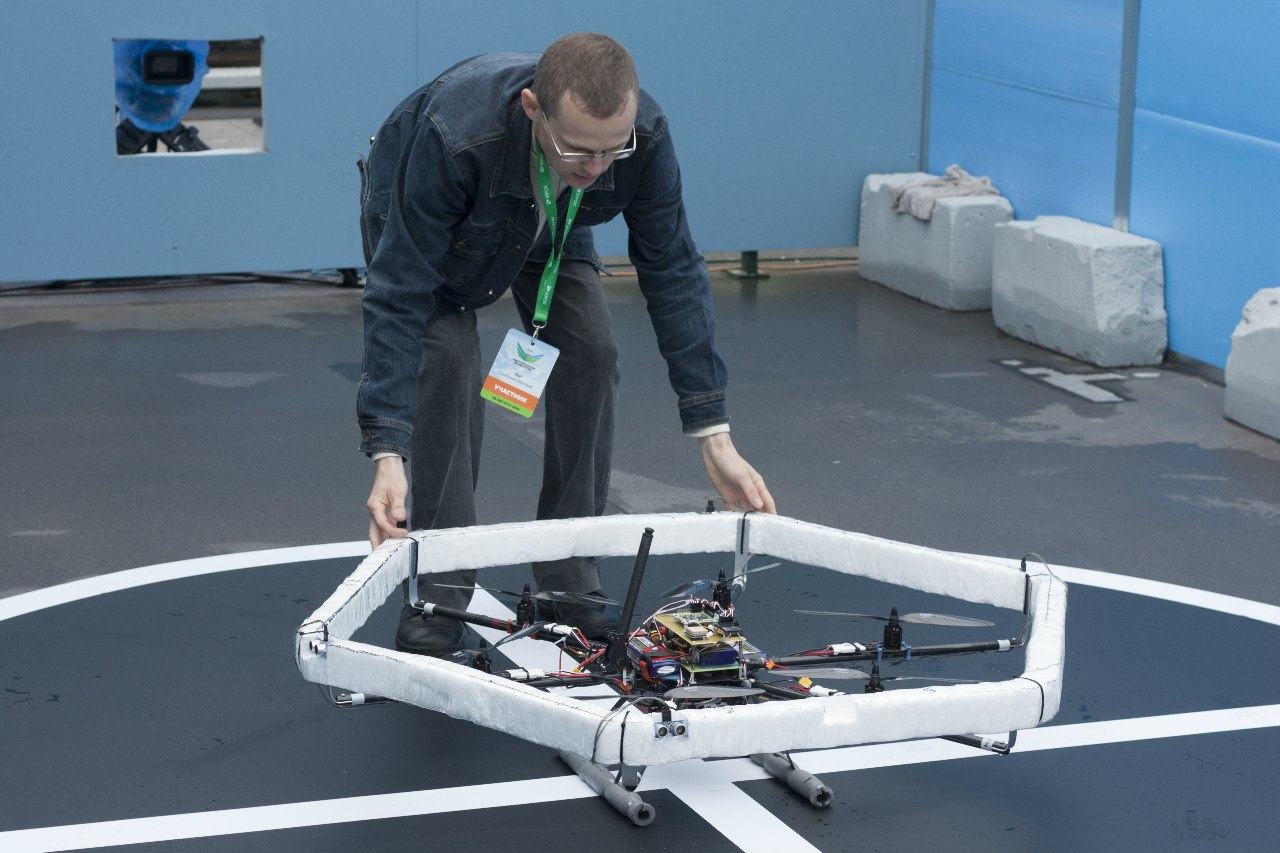
Special attention was paid to the issue of security - all copters were equipped with screw protection. Thus, after a collision with a wall or when falling, everything remained intact. This saved money and repair time.
3. Scheme of electrical equipment drone 2013
For a faster solution of the task and reduction of labor costs, it was decided to build drons from ready-made modules than, for example, to do everything on the basis of a single-board computer that would perform all the calculations. For example, you can buy a flight controller that can hold the aircraft in the horizon and stabilize the flight, and control using another device (microcontroller, computer) —the autopilot, which receives data from the sensors, and the radio modem (more on that later), and transmit commands to the flight controller for moving forward, backward, etc. Autopilot also performs all the intellectual work (navigation, etc.).
Since analyzing an image (determining landing markers) is quite a resource-intensive task, calculations should be performed either on board on a powerful microcomputer, or analysis should be performed outside the drone at the base station (laptop), and the image from the drone should be transmitted to the base station via Wifi, or via analog video transmitter. Thus, by recognizing the markers, such a scheme was obtained (with an analog video transmitter):
1) the image from the video camera from the side of the drone was transmitted through the video transmitter;
2) taken by the video receiver at the base station;
3) the analog video signal came to the laptop through video capture (VIDEO-> USB);
4) on the laptop, the image was recognized using the program (OpenCV);
5) the radio coordinates of the “seen” marker (X, Y) were transmitted via radio modem to the autopilot;
6) according to the obtained screen coordinates, the autopilot determined the location of the landing pad marker relative to the drone and made the decision on landing or navigation for landing.

2013 drone electrical equipment layout
4. Choose a flight controller
Flight controller was available - MultiWii ALL-IN-ONE; was removed from the existing FPV quadrocopter:
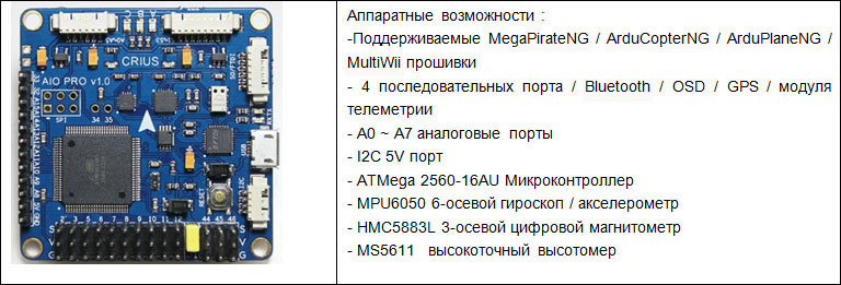
In terms of flight characteristics, this flight controller is not bad with manual control, but it is significantly inferior in quality to stabilization to professional controllers with more powerful hardware and mathematics.
When used for a robot with standard firmware, it was not possible to configure MultiWii, because the firmware was adjusted.
Using professional controllers with open firmware like OpenPilot or PixHawk for the project would be more reasonable, but at that time it was impossible.
5. Select the sensors
For orientation in space, it was necessary to choose sensors for the drone.
Selection list:
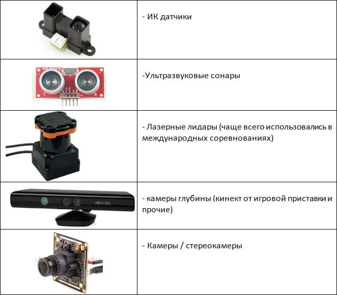
Ultrasonic sonars and infrared sensors were among the available and easy-to-use sensors. Since the budgetary ultrasonic measurement range was longer (up to 4.5 meters) than the infrared (up to 1.5 meters), they were chosen as the main sensors for the drone.
It took a total of 5 pieces: 1 sonar was directed down to maintain height, and 4 pieces. around the perimeter for orientation from the walls.
I had to study the ultrasound sensors well to make them work correctly. For a deeper and safer study, a ground-based robot tank was built with installed sonar. The tank kept a given distance to an obstacle, for example, a piece of paper that could be moved, and the robot moved behind it. The data was logged and then it was not difficult to analyze and determine the nuances.
 Ultrasound sonars can be classified according to various characteristics, such as effective angle (directivity pattern), distance measurement distance, and so on. Moreover, the quality of measurement strongly depends on the various characteristics of the sensors. For example, wide directional sonars work well for large angles of deviation from the surface to which the distance is measured, while narrowly focused ones are lost. Also, wide-directional “beat” further (depending on the model) and measure the distance from almost any surface (asphalt, fabric, etc.). But they have a small drawback - the results of the measurements slightly “jump”, unlike narrowly focused ones, respectively, the obtained values need to be filtered.
 Any sonar demanded a "quality" food, otherwise their testimony "jumped" and it was impossible to navigate by them. For quality power, you need to use power filters or have a separate DC-DC, full recommendations can be found here . After the tank was no longer needed, it became a toy. With the camera installed on board (sonar removed), it was possible to skate around the apartment on FPV.
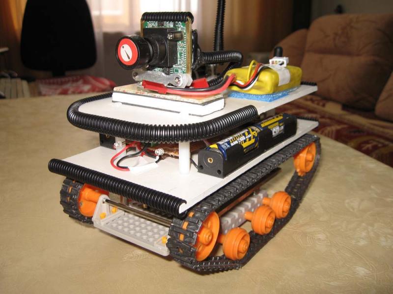
More information about the tank: forum.rcdesign.ru/blogs/45616
6. Choosing the autopilot, or rather - popayaya a little
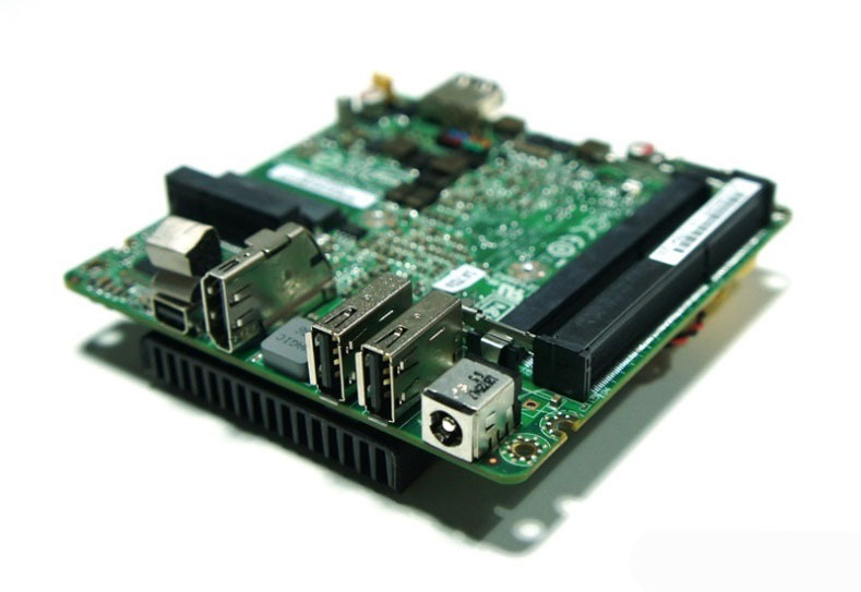
In order to read the data from the sonars, make decisions on navigation and send data to the flight controller, a separate calculator was needed - the autopilot. Since there was knowledge of the Atmega family of controllers, for 2 pm I soldered the poll fee to Atmega162 (the only controller in the DIP package and having 2 UART ports, which could be bought at the local radio store), and which was later replaced by Atmega128 (the firmware grew and did not fit in the memory of the controller).
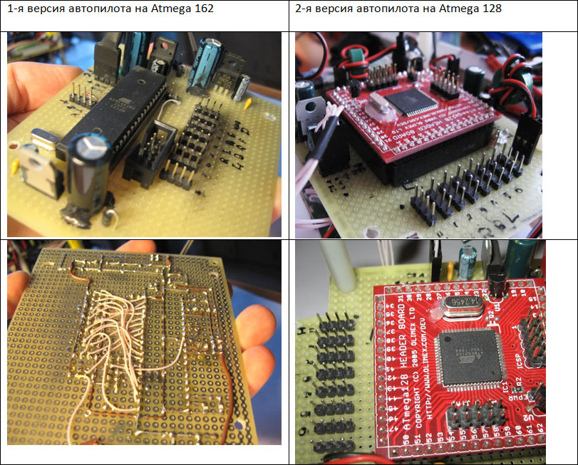
The pins on the board are connectors for connecting sonars. The main advantage of using these controllers in comparison with controllers on the Arduino was that the code could be debugged (debugged) with a debugger via JTAG! That is, at any time, you can stop the program and see everything that interests - the values of variables, counters, and others, as well as in case of an error, step by step to find where it originated.
7. Learn to keep the height
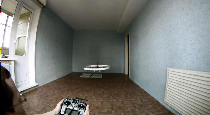
In order to speed up development / testing in a short time, it was decided to conduct tests in an apartment instead of going somewhere and losing valuable time. Without thinking twice, a stand was created for testing in a room of 12 square meters. meters
 Hooks were screwed in the ceiling and in the field, and a strong paraglider sling was stretched between them. In the drone frame was installed vertical guide - carbon tube. On top there was a limiter, not allowing the copter to rest against the ceiling. As a result, the rotor could only move vertically, as required, in order to adjust the PID height-retention factors safely for yourself and the rover.
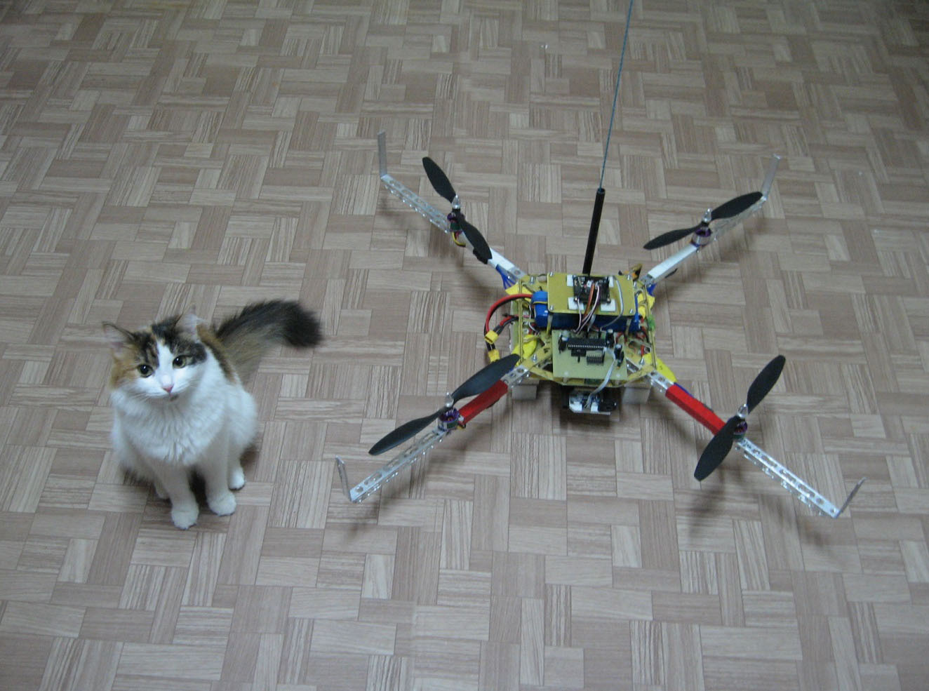
More information about the landfill can be viewed in the video:
It took a lot of time to tune the PIDs, but managed to get a good handle on the regulatory mechanism through personal experience and practice. I also decided on a model of sonars to keep the heights that were acceptable working - these are widely-directed DYP-ME 007 v1.0. Popular HC-SR04 worked worse - “hung” on a bad surface.
Thanks to the work on the stand "live", we managed to achieve a good result, the copter perfectly kept the given height.
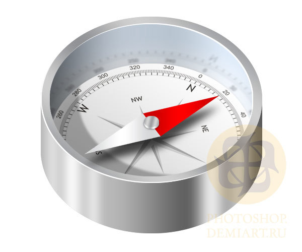
8. Hold a course or a bit of compass.
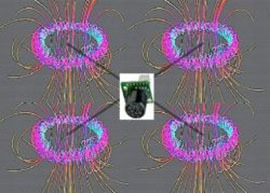
One of the following problems was holding the course (Yaw axis), that is, so that the copter does not spin around its own axis. The decision to use the compass, which was on board the flight controller, turned out to be simple at first glance, but subsequently unacceptable, because the compass refused to work in Moscow at the organizers training ground (power lines, etc.). However, this decision made it possible to continue testing in my apartment and move on to the following tasks - move on.
In Moscow, after finding out on a test that it was impossible to navigate the compass, it turned out to turn off the compass and write your own Yaw hold algorithm. For this, I entered the value of the calculated angle Yaw (by the way, this angle is also calculated on the Open Pilot CCD3 flight controllers, since there is no compass on board at all, and the angle of rotation can be seen in the setup program). The value of the angle was calculated according to the data from the gyroscope (angular acceleration along the Yaw axis), the formula was chosen empirically. Then I measured in a stationary state how much this value runs off in 5 minutes (there was a slight drift in one direction), and corrected this angle at regular intervals to reduce the resulting drift to zero. On the table, everything worked perfectly, on the copter, in the absence of strong vibrations, this also had to work.
9. Keeping distance from one wall
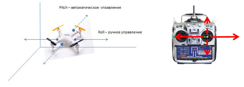
Fixed one sonar (focused HY-SRF-05) in front of the copter to automatically hold the position back and forth (along the pitch axis). From the control panel, manually controlled moving the copter left and right (along the Roll axis), and in case of unsuccessful PID adjustment (PID) of the regulator, corrected the displacement of the copter back and forth, when the stick stick rejected 10% from the center, the copter switched to manual control by axes back and forth (pitch).
Having suffered a lot with tuning the PID (PID) of the regulator and enumerating its coefficients, I got 3 control coefficients, at which the device almost “held” tolerably by the wall:
P-position (P position), when the regulation error is considered, as the difference between the desired distance from the wall and the current data from the sonar.
D - position (D position), the speed of movement from \ to the wall.
D for speed (D-velocity), the acceleration of movement from \ to the wall.
And (I) - the non-speed position factor was not taken into account = 0.
Further searches for truth have already translated into the code of the flight controller. As it turned out in the MultiWii code, many of the settings in the code are chosen empirically. You can fly with your hands, but for the robot everything was not very well formed. I decided to rewrite the PID controller and do the same: P and D position + D velocity, conjured with filters, which I borrowed from the code of the flight controller ArduPilot and got the result to “good”, but I certainly don’t compare with professional controllers.
When I combined everything, I got a good result for the first time: retention in the range of 1 meter horizontally at a height of 50 cm. I tried to make the height higher, the range of the bumper also increased.
10. Connecting the rest of the sonars and setting up joint work of the sonars.
Since sound tends to be reflected, then in order not to catch the reflected signal from one sonar to another, I interrogate the sonars sequentially. The maximum polling frequency of the used sonars is 20 Hz; it turns out that if you scan the sonars sequentially in succession (and there are 5 of them), then everyone will be polled at a frequency of 4 Hz. Thanks to the cunning algorithm, in short, the essence of which was to interrogate "uninteresting" sonars (for example, back when moving forward) less often - I received 5 Hz (5 times per second, in principle, not bad!)
Concerning stability there were the following thoughts:
 Obviously, the more frequently the sonars are polled (the higher the polling rate), the more accurately the copter can be positioned, but not only the frequency is important, but also the system response time or the delay between direct measurement, for example, the distance to the wall and the impact on the motors taking into account measured distance.
How quickly does the current system react to the received values, how quickly (in what time) does the drone react to the measurement - will the control signal to the engines give, after calculating the PID, transfer data from the autopilot to the flight controller and read the distance from the sensor?
 It is easy to imagine such a situation, for example, if information from a video camera came into our eyes (through a monitor or glasses) with a delay of 1-2 seconds, would it be easy to move, despite the fact that the frequency would remain 25 frames per second? I would have to go very slowly so as not to fall. Well, if you try to walk this way, for example?
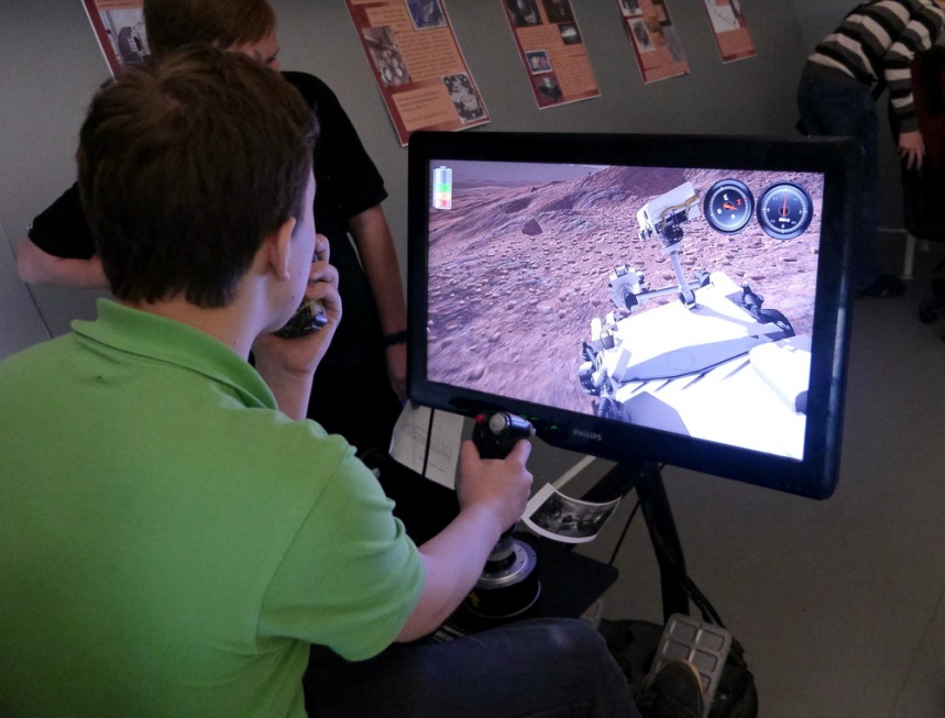
Here is another example: the signal from the moon rover from the moon comes with a delay of 3 seconds, while from Mars this time is measured in minutes, and it is simply impossible to control it from the earth (or the speed of the rover would be very, very slow).
Calculate the response time for the resulting drone system:
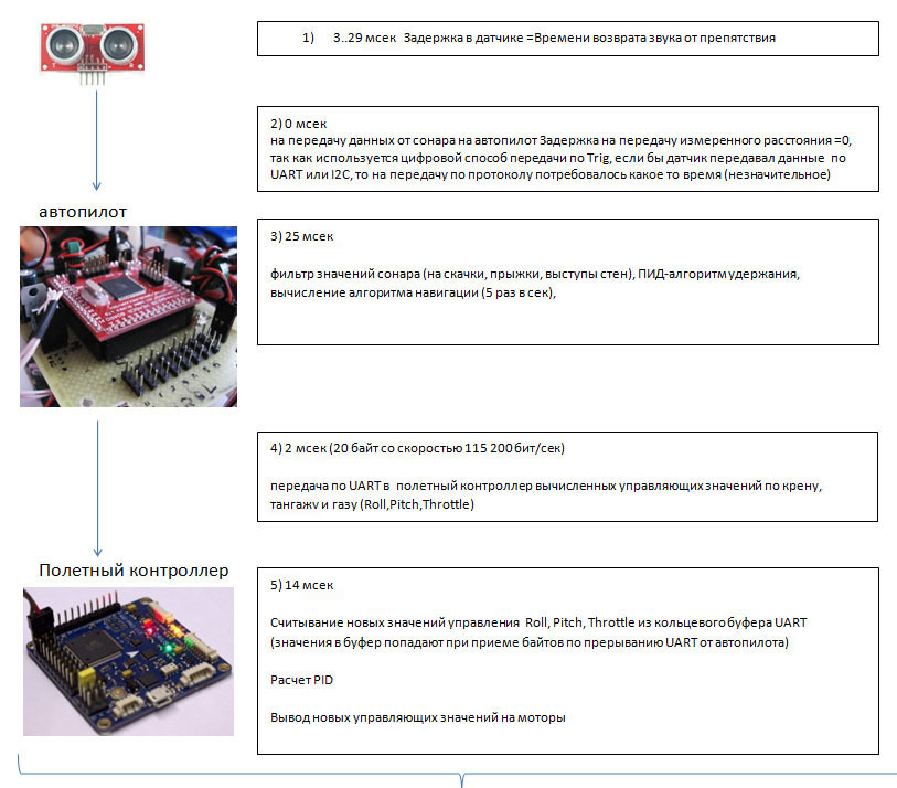
TOTAL pre-delay: 3..29 + 0 + 25 + 2 + 14 = 44..70 ms.
Detailed description:
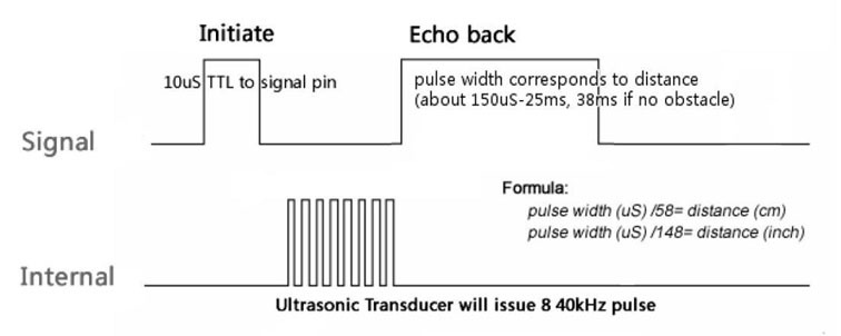
1) After a signal is sent to the sonar to measure the distance (trig), the ultrasound module emits an ultrasonic signal, a certain time elapses until the signal-sound returns after reflection from an obstacle. This time is fixed in the sensor-sonon and output via the analog or digital output of the sensor.
2) Since I used the digital output (Echo) of the sonar, on which the signal (+) is generated by receiving the reflected echo, it is recorded immediately on the autopilot controller (by interruption) - in fact, the transmission of the measured distance occurs without delay, unlike, for example, UART or I2C transmissions, when the sonar controller would have to transmit the data sequentially, and the autopilot controller would have to receive it.
3) The value obtained by the autopilot controller is calculated and filtered. The calculated distance to the wall or floor is “fed” to the autopilot PID controller by holding from the wall or floor. As a result, it receives a new value for controlling the crank on roll (pitch), pitch (pitch) and “gas” (throttle).
4) The obtained control values (Roll, Pitch, Throttle) are transmitted via the UART port to the flight controller (MultiWii).
5) The flight controller reads the data into the ring buffer and after a certain time (50 times per second) “feeds” it to the PID controller (which, in fact, is a multi wii stabilization system), after which the new value of the control actions are mixed (depending on the scheme LA (quadcopter, hexakopter, etc.) and served on the engine controllers.
Since the successive cycle of the survey of sonars is 20 Hz , the time that can be spent on each sonar is no more than 50 ms. The definition of the distance by the sonar takes up to 29 ms, and accordingly, 21 ms is left for the calculations (filters, PID and path selection algorithms).
This time (21 ms) was not enough for a slow 8-bit controller, so the option was invented when the 50 ms interval is used to calculate the control actions from the previous sonar value, and the current cycle simply reads the value of the current sonar. This solution increased the response time of the system by 50 msec, but allowed it to exist in such a configuration of low-performance iron.
TOTAL delay (lag) = 44..70 ms + 50 ms = 94..120 ms, in essence, this delay is the response of the current system to the measured distance.
Obviously, the slower the response, the less stable the device will behave at any PID controller and the sensor sampling frequency. That is, the stability of the device depends not only on the sampling frequency of the sensors, but also on the “response” of the aircraft system to the measured distance (lag values or response time).
11. Possible optimization
How was it possible to reduce the lag value in the current system? Optimization options:
 1) Using a faster controller for autopilot, for example AWP (172 MHz 32 bits)
a value of 25 ms - which includes the calculation of the distance and the PID controller with transmission can be reduced to 2 ms (- 23 ms).
Due to this, it would be possible to read and perform the calculation in one survey cycle, and this is still (- 50 ms)
TOTAL delay (lag) with optimization = 94..120 ms - 23 ms - 50 ms = 21..47 ms
 2) An even more advantageous solution, if the flight controller and autopilot are one fast controller or computer, the scheme would be even faster, as it would save time on transferring information from the autopilot to the flight controller, as well as increase the frequency of the flight controller stabilization system ( in MultiWii, this frequency is about 300 Hz)
12. Standalone hanging (holding distance from walls + holding height)
After we managed to keep the height of the sonar and more or less keep the distance from one of the walls, it was possible to cling the 3rd sonar to the left or right side of the copter, and learn to hang in the room in automatic mode. But the kopter dangled along each axis and eventually spun counterclockwise, gaining amplitude. The downside was also that the drone "sluggishly" held the course (Yaw axis), especially strongly twisted the apparatus near the wall. Also moving from one wall to another, the device lost a bit of height, further slowing down in front of the wall, he tried to gain height, thereby almost firing in the opposite direction. When installing large PID values for yaw, the device tried to level out as much as possible at the moment of spinning near the wall, thus, working on almost two diagonal engines (a feature for controlling multi-rotor systems along the yaw axis), lost controllability (since in fact only 2 of 4 engines were spinning in quadcopter) and flew into the wall.
A lot of time was spent on the stabilization of the apparatus along the course (Yaw axis), the selection of the PIDs of the autopilot and the flight controller. I also had to come up with a couple of tricks of the apparatus’s behavior in order to prevent the buildup. The result was a more or less stable behavior:
13. Navigation in the maze
For the passage of the competitive landfill there was no need to use complex algorithms and construct maps; the simplest rule of the maze “right hand rule” approached the maze. Slightly modified it and made it on the state machine. In short, the essence lies in a few simple traffic rules:
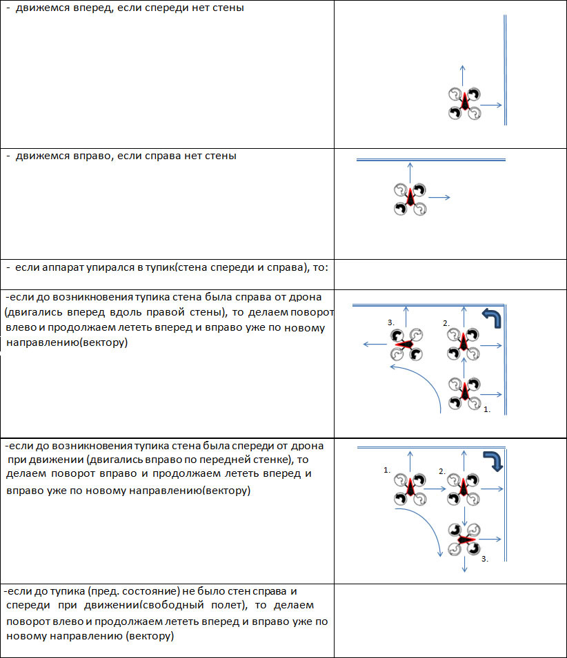
To move the drone forward / backward / right / left, the autopilot sends the appropriate commands to the flight controller to tilt the platform in the appropriate direction. If the walls in the direction of motion are not "visible" on the sonon, the platform bends by 5 degrees (selected the angle manually). In order for the drone not to accelerate, at regular intervals of time, it assumes a horizontal position and moves by inertia (without tilting in any direction).Additionally, for rough speed control, I used a GPS receiver, while fixing the speed exceeding the critical one (it was also chosen empirically), the drone slows down, that is, it deviates in the opposite direction from the direction of movement. For movement within sight of the distance sensor - sonar, the hold distance from the wall simply changes.
14. Detection of landing point markers
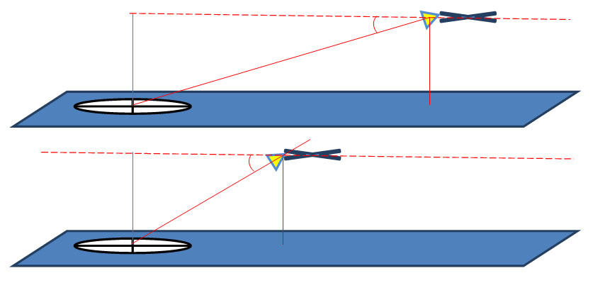
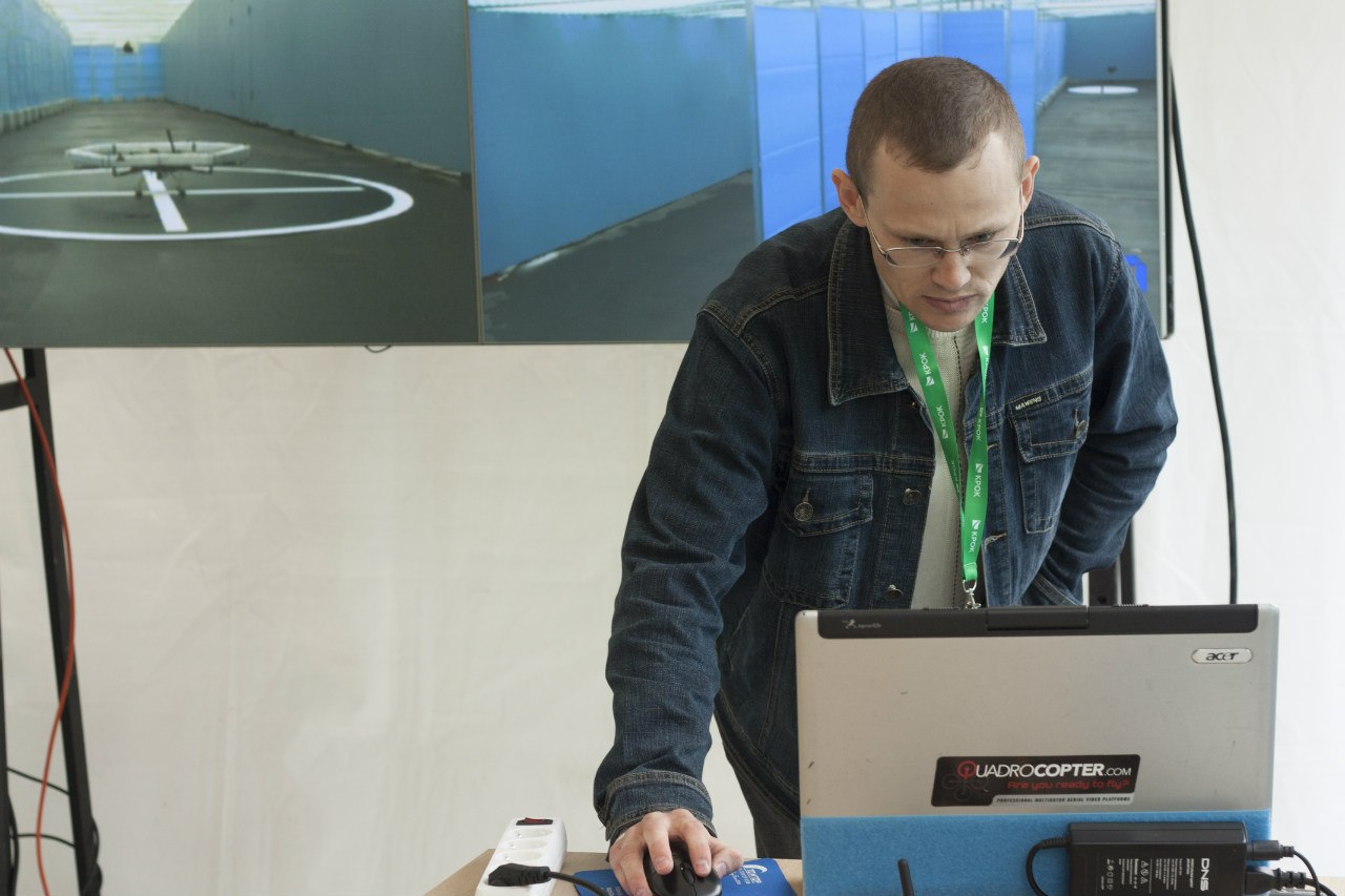
 A camera was installed on the drone, the image was transmitted via a video transmitter to a laptop. And further, if the marker was determined (recognized), then the data on the screen coordinates of the marker was transmitted to the autopilot on the radio modem. On the basis of the data obtained, the autopilot calculated the distance to the “target” relative to the kopter and the visible walls (described in detail in paragraph 3). Then he tried to maintain this distance, and the landing program was turned on, consisting in a slow decrease in the height of the hover.
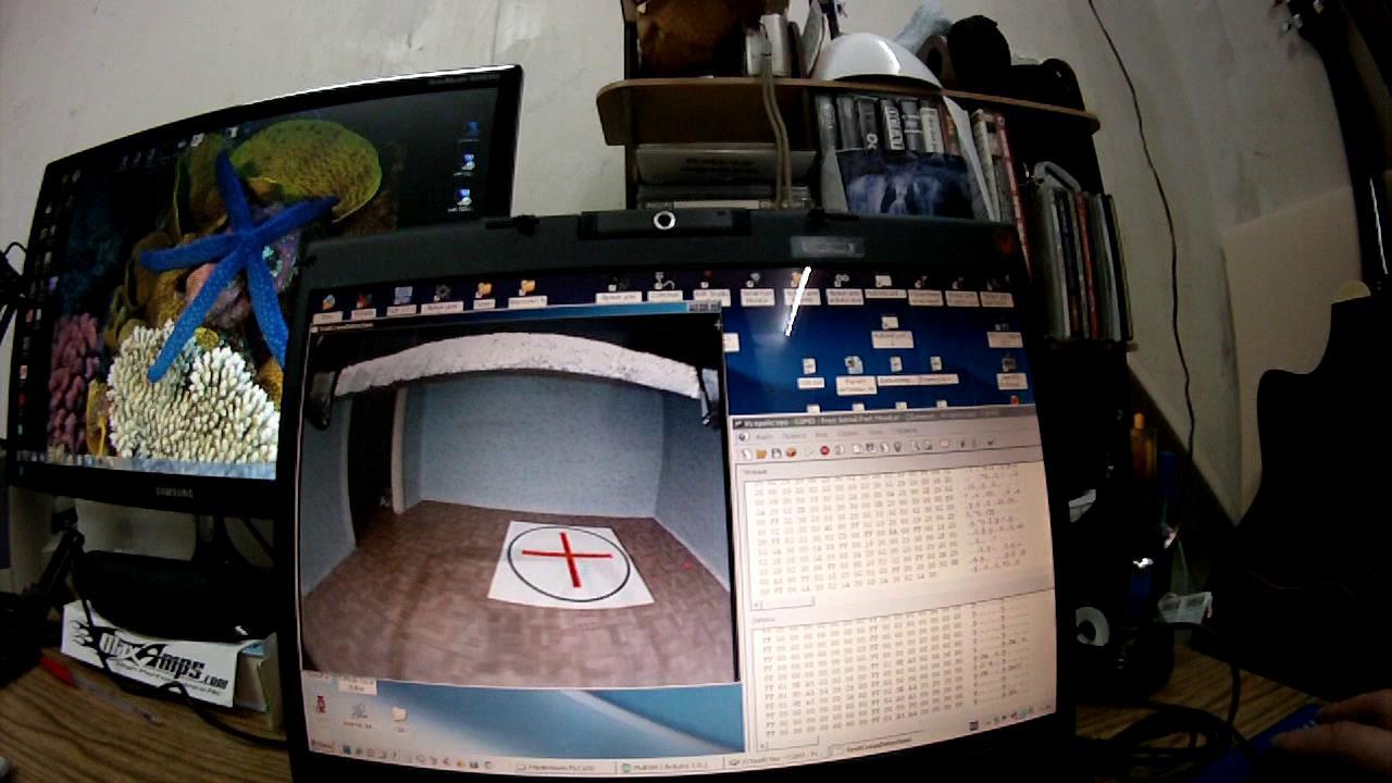
In the final version of the robot, it was possible to implement a pivoting mechanism for the camera (the camera turned up and down along the Pitch axis). Thus, the target tracking mechanism was organized, and when approaching the cross, the camera turned down, keeping the center of the landing pad at the center of attention of the camera. Thus, the time of "target tracking" was increased and, therefore, the accuracy of landing, too.
The recognition of the cross marker in the circle was done using Open CV, the algorithm used to find the intersection of straight lines was used by an individual person in the team who joined the project at the last project dates, so it could not be included in the list of participants (according to the rules of the contest organizers).

15. Trip to Moscow
Having passed all control points for participation in the competition, our team was allowed to participate in the final. At the time of the trip, not everything was ready in the new platform based on the hexacopter, because it was decided to finalize the preparations in Moscow at the test site.
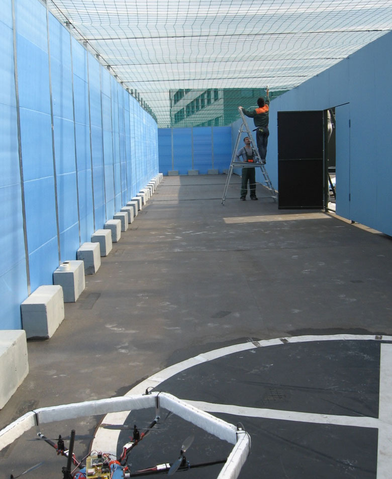
The landfill was completed in the testing process.
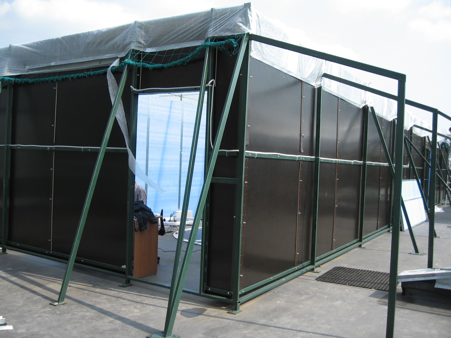
Competitions were divided into 2 days, some photos can be viewed on the website of the organizers .
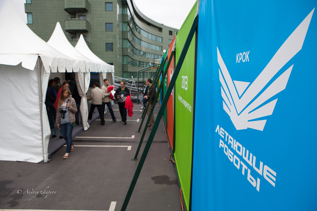
Before the start:
Waiting area in the parking lot.
The first attempt of our team failed, the robot flew past, but hooked the fence and touched the floor, but took off and bravely got back.
In the second attempt to navigate everything went well, the robot did not touch the walls, but did not land on the landing markers, although the markers were well recognized at the base station on the laptop.
And after the competition turned out to be an almost ideal version of the span, with a landing at both ends.
Results
4 people participated in the work on the project of the flying robot in our team. One person was responsible for recognition, one was an excellent specialist in the C language and well versed in AVR controllers, advised in difficult moments of the project. I, as the team captain, designed the drones, programmed and tested, my wife dealt with organizational issues when traveling to Moscow. Also for testing the robot required premises - testing grounds. Thanks to friends who provided their homes, garages and offices. Despite the seemingly small result, a lot of work was done. 90% of the time was spent on learning something new, organizational issues, testing and overcoming difficulties, without which the project would not move.
The competition of 2013 gathered a lot of participants, in the finals on tests and during the competition it was possible to talk a bit with colleagues (the rest of the time was spent on refining and tuning the drone).
At the competitions, the weather conditions spoiled the picture a bit and there were problems with wireless communication (wifi) for most of the participants, including the organizers. For many people, including us, it was a surprise on the tests that the compass doesn’t work on a real range (power cables, etc.).
In general, for the first competition for "adults" it turned out very well.
List of sources about the competition:
www.robots.croc.ru
habrahabr.ru/company/croc/blog/192704
habrahabr.ru/post/193304
Source: https://habr.com/ru/post/253159/
All Articles