Automatics for the KTC or extend battery life
As a result of the publication of stories about my autonomous solar power system, described here , here and here , similar questions were frequent: what is the payback period and how long will the system last? It should be noted that one of the most expensive and capricious parts of the system are batteries. It is energy storage devices that wear out the fastest, the battery capacity drops and the number of remaining charge-discharge cycles decreases steadily. Motorists are well acquainted with the reduced capacity of batteries, when a sudden sharp frost leaves no chance for the old battery to start the car.
I wondered how to determine the residual battery capacity so that it was as simple and fast as possible.
')
First, a little theory to understand how to measure the residual capacity of a battery and what it takes.
The charge-discharge control and training cycle is conducted to prevent sulfation and to determine the battery capacity. Control and training cycles are carried out at least once a year and are performed as follows: charge the battery with a normal current to a full charge; maintain AB for 3 hours after the cessation of charge; correct the density of the electrolyte; include charging for 20-30 minutes for mixing the electrolyte; conduct a test discharge with a constant normal current of 10-hour mode and control the time of full discharge to a voltage of 1.7 V per bank (10.2 V per AB); battery capacity is defined as the product of the discharge current value and discharge time. After the test discharge, the battery is immediately charged and fully charged. If it turns out that the capacity of the battery is less than 50% of the nominal, it is considered faulty.
Manual test discharge requires the constant presence of staff to fix and adjust the discharge current. (c) taken from here
That is, to determine the residual capacity, we need to discharge the battery with a load with a known and constant power up to a value of 10.2 (in other sources, it is recommended to discharge a 12V battery not lower than up to 10.8V) Volt. You can just buy such a device and not wrestle with the invention of a bicycle, but the daily struggle with laziness requires new accomplishments and inventions.
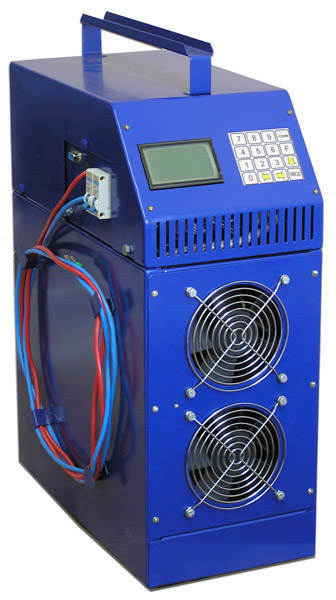
So, guided by the principle “The simpler, the more reliable”, it was decided to assemble our own automated device for measuring the residual capacity of the battery, and at the same time, carrying out the KTC. Since I already had a charger , there was no need to reinvent the wheel. It was necessary only to turn on this charge on time. But it is necessary to discharge something that has a constant load, regardless of the ambient temperature and battery voltage. The easiest way is to discharge it with car incandescent bulbs. The power rating is written directly to them, so the current consumption can be calculated by simple arithmetic: W / 12 = load current. That is, a 60 watt lamp will consume 5 amps. The battery is discharged with a current of 10% capacity or 0.1 ° C and charged with the same current.
As a result of a five-minute meditation, a ToR for the future device was compiled:
1. Fixing the start time of the discharge process
2. Monitoring Battery Voltage
3. Upon reaching the critical voltage, the device must disconnect the load and turn on the charger
4. Fixing the end of the discharge process
From all this followed that we need:
1. Arduino Nano - 175 rubles
2. RTC1307 - 56 rubles
3. Relay - 131 rubles
4. LCD 2x16 i2c - 222 rubles
5. 3 resistors of 10 kΩ each, a certain amount of wires - 50 rubles
Total: 634 rubles
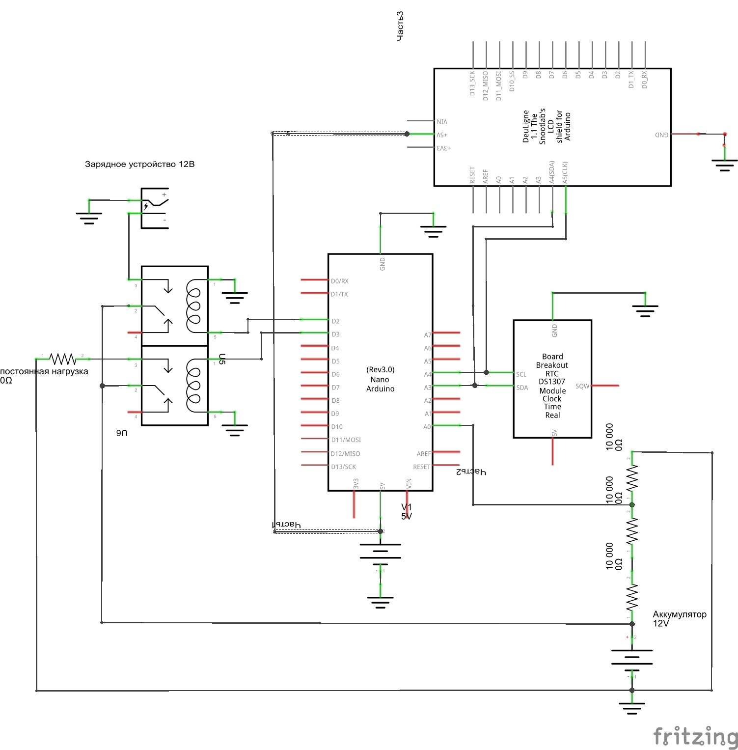
In order for Arduin to understand the voltage at each time point on the battery, it was necessary to connect the battery to the Arduino. This can not be done directly, since the analog inputs of the controller can take no more than 5V, so it was decided to assemble a voltage divider of 3 resistors of 10 kΩ each. Negative battery and minus controller are directly linked. The controller was powered from a separate power source. Connection diagram and code are presented below:
How does the device work? Elementary!
The load is connected to the first relay, to the second memory. And it is better to break the high-voltage power supply circuit of the charger, so as not to leave the device turned on without a battery. When the controller is turned on, the first line displays the current time and the time the load started working. The second line displays the current voltage on the battery and the end time of the discharge when the battery reaches the critical voltage. As soon as the values are reached, the load relay is switched off and the charge relay is switched on. If you add a couple of buttons, you can easily adjust the voltage threshold adjustment or the real-time clock setting. At this stage, there was no such task, so the code is as simple and functional as possible. Subtracting from the end of the time of the start of discharge, you can get the capacity, if you multiply the time by the current consumed by the load.
Conclusion
So, it is very easy to organize a control and training cycle for any battery with a charger, 600-700 rubles for spare parts and a couple of hours. Do not forget that a charged battery lasts longer, and periodic KTC gives confidence at least that you know for sure that the car will start in the morning, despite any frosts.
I wondered how to determine the residual battery capacity so that it was as simple and fast as possible.
')
First, a little theory to understand how to measure the residual capacity of a battery and what it takes.
The charge-discharge control and training cycle is conducted to prevent sulfation and to determine the battery capacity. Control and training cycles are carried out at least once a year and are performed as follows: charge the battery with a normal current to a full charge; maintain AB for 3 hours after the cessation of charge; correct the density of the electrolyte; include charging for 20-30 minutes for mixing the electrolyte; conduct a test discharge with a constant normal current of 10-hour mode and control the time of full discharge to a voltage of 1.7 V per bank (10.2 V per AB); battery capacity is defined as the product of the discharge current value and discharge time. After the test discharge, the battery is immediately charged and fully charged. If it turns out that the capacity of the battery is less than 50% of the nominal, it is considered faulty.
Manual test discharge requires the constant presence of staff to fix and adjust the discharge current. (c) taken from here
That is, to determine the residual capacity, we need to discharge the battery with a load with a known and constant power up to a value of 10.2 (in other sources, it is recommended to discharge a 12V battery not lower than up to 10.8V) Volt. You can just buy such a device and not wrestle with the invention of a bicycle, but the daily struggle with laziness requires new accomplishments and inventions.
So, guided by the principle “The simpler, the more reliable”, it was decided to assemble our own automated device for measuring the residual capacity of the battery, and at the same time, carrying out the KTC. Since I already had a charger , there was no need to reinvent the wheel. It was necessary only to turn on this charge on time. But it is necessary to discharge something that has a constant load, regardless of the ambient temperature and battery voltage. The easiest way is to discharge it with car incandescent bulbs. The power rating is written directly to them, so the current consumption can be calculated by simple arithmetic: W / 12 = load current. That is, a 60 watt lamp will consume 5 amps. The battery is discharged with a current of 10% capacity or 0.1 ° C and charged with the same current.
As a result of a five-minute meditation, a ToR for the future device was compiled:
1. Fixing the start time of the discharge process
2. Monitoring Battery Voltage
3. Upon reaching the critical voltage, the device must disconnect the load and turn on the charger
4. Fixing the end of the discharge process
From all this followed that we need:
1. Arduino Nano - 175 rubles
2. RTC1307 - 56 rubles
3. Relay - 131 rubles
4. LCD 2x16 i2c - 222 rubles
5. 3 resistors of 10 kΩ each, a certain amount of wires - 50 rubles
Total: 634 rubles
In order for Arduin to understand the voltage at each time point on the battery, it was necessary to connect the battery to the Arduino. This can not be done directly, since the analog inputs of the controller can take no more than 5V, so it was decided to assemble a voltage divider of 3 resistors of 10 kΩ each. Negative battery and minus controller are directly linked. The controller was powered from a separate power source. Connection diagram and code are presented below:
Sketch KTC
// Date and time functions using a DS1307 RTC connected via I2C and Wire lib #include <EEPROM.h> #include <Wire.h> #include <DS1307.h> #include "RTClib.h" #include <LiquidCrystal_I2C.h> int rtc[7]; byte rr[7]; LiquidCrystal_I2C lcd(0x27,16,2); // set the LCD address to 0x27 for a 16 chars and 2 line display #define RELE_NAGRUZKA 2 // 2 #define RELE_ZARYADKA 3 // 3 int analogPin = 0; int flag=0; float val=0; float valkoef=0; void setup () { DDRC|=_BV(2) |_BV(3); // POWER:Vcc Gnd PORTC |=_BV(3); // VCC PINC3 RTC.get(rtc,true); lcd.init(); // initialize the lcd lcd.backlight(); lcd.home(); pinMode(RELE_NAGRUZKA, OUTPUT); // pinMode(RELE_ZARYADKA, OUTPUT); // lcd.clear(); digitalWrite(RELE_NAGRUZKA, HIGH); digitalWrite(RELE_ZARYADKA, HIGH); RTC.SetOutput(DS1307_SQW32KHZ); EEPROM.write (0, rtc[2]); // , EEPROM.write (1, rtc[1]); // , } void loop () { val = analogRead(analogPin); // valkoef=val/74,49; // RTC.get(rtc,true); lcd.setCursor (0,0); lcd.print (rtc[2]); lcd.print (":"); lcd.print (rtc[1]); lcd.print (":"); lcd.print (rtc[0]); lcd.print (" str"); lcd.print (EEPROM.read(0)); lcd.print (":"); lcd.print (EEPROM.read(1)); lcd.setCursor (0,1); lcd.print (valkoef); lcd.print (" "); lcd.print (flag); if (valkoef < 10.72) { flag=1; EEPROM.write(2, rtc[2]); // , EEPROM.write (3, rtc[1]); // , } if (flag==1) { digitalWrite(RELE_ZARYADKA, LOW); // digitalWrite(RELE_NAGRUZKA, HIGH); // lcd.print (" stp"); lcd.print (EEPROM.read(2)); // lcd.print (":"); lcd.print (EEPROM.read(3)); } if ((valkoef > 10.72) && (flag==0)) { digitalWrite(RELE_NAGRUZKA, LOW); } else { digitalWrite(RELE_NAGRUZKA, LOW); } delay(500); } How does the device work? Elementary!
The load is connected to the first relay, to the second memory. And it is better to break the high-voltage power supply circuit of the charger, so as not to leave the device turned on without a battery. When the controller is turned on, the first line displays the current time and the time the load started working. The second line displays the current voltage on the battery and the end time of the discharge when the battery reaches the critical voltage. As soon as the values are reached, the load relay is switched off and the charge relay is switched on. If you add a couple of buttons, you can easily adjust the voltage threshold adjustment or the real-time clock setting. At this stage, there was no such task, so the code is as simple and functional as possible. Subtracting from the end of the time of the start of discharge, you can get the capacity, if you multiply the time by the current consumed by the load.
Conclusion
So, it is very easy to organize a control and training cycle for any battery with a charger, 600-700 rubles for spare parts and a couple of hours. Do not forget that a charged battery lasts longer, and periodic KTC gives confidence at least that you know for sure that the car will start in the morning, despite any frosts.
Source: https://habr.com/ru/post/253143/
All Articles