Phase AC load control with FLProg
A free day was issued and I finally decided to try out the high-speed counter unit in the delay line mode. This mode was created mainly for the implementation of phase load control, but so far I have not had time to roll it in real use. I think it's time.
I made the block binding according to this scheme:
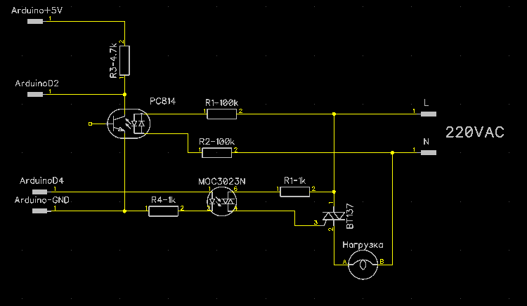
On the PC814 optocoupler assembled zero detector. Since the block operates on interrupts, only the controller inputs to which hardware interrupts bind can serve as the input of the zero detector. In the case of UNO, these are inputs D2 and D3.
On optosimistor MOC3023 assembled triac control unit. To control this unit, you can select any free digital output of the controller.
Project outline

Res - Analog input. At the input is a variable resistor.
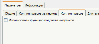
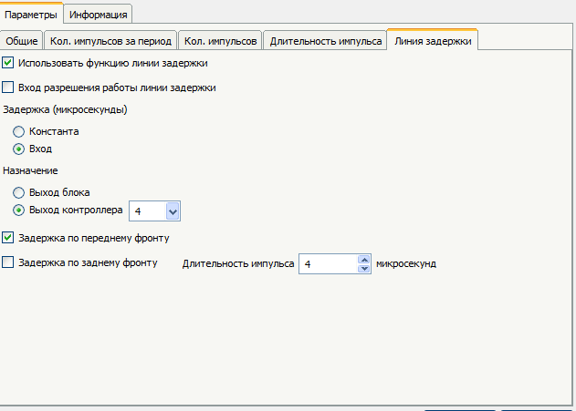
SCT2 block - Speed counter block. (Element library -> Counters -> SpeedCounter)
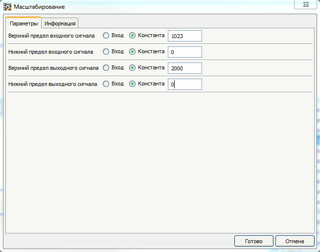
Since all optocouplers are different - it is necessary to configure the Scale unit. To do this, we are currently modernizing the project.
')

Now the value of the delay once a second will be displayed in Com-port. What is it for? Since the leading edge of the pulse from the zero detector comes a little before the true moment of the sine wave transition through 0 (at the moment when the optocoupler LED goes out), we need to determine this time to set it as 100% of the power at the load. Here are the settings for the Scale block.
Fill the program into the controller and launch the monitor of the comport. When the variable resistor is rotated, the lamp will either light or flicker. That's how it looks.
We achieve uniform maximum burning. The value obtained through the comport write. This value will be entered in the field "Lower limit of output value" Scale. Now we will rebuild the second border. Change the values in the Scale block again.

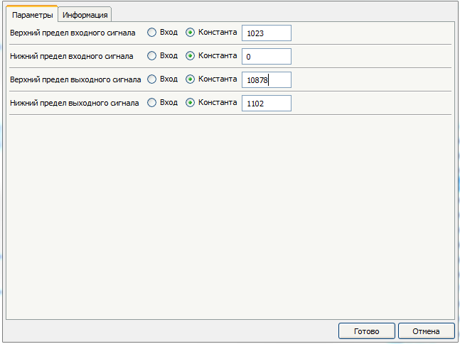
The duration of the half-cycle mains voltage is 10,000 microseconds. But we have a pulse shifted 1102 microseconds earlier. Accordingly, in order to establish a full power zero, the maximum delay should be increased by as much. You can of course just put 11102, but it's better to check. Fill the program into the controller and launch the monitor of the comport. We achieve the moment of transition from flickering burning to full extinction. We write the value from the comport. Here's what it looks like.
Well, now you can use the obtained values. Fill the block Scale
Well, that's what happened
Now it is possible to remove the generator and data transmission blocks of the comport, and to supply the Scale input the required regulating value. Pay attention to the field “Upper limit of input value” of the Scale block, you must enter the value of the regulating value corresponding to 0 power at the load, and in the field “Lower limit of the input value” value corresponding to 100% of the power.
I made the block binding according to this scheme:
On the PC814 optocoupler assembled zero detector. Since the block operates on interrupts, only the controller inputs to which hardware interrupts bind can serve as the input of the zero detector. In the case of UNO, these are inputs D2 and D3.
On optosimistor MOC3023 assembled triac control unit. To control this unit, you can select any free digital output of the controller.
Project outline
Res - Analog input. At the input is a variable resistor.
SCT2 block - Speed counter block. (Element library -> Counters -> SpeedCounter)
Block settings: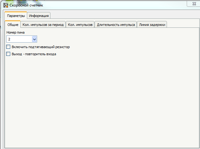


Since all optocouplers are different - it is necessary to configure the Scale unit. To do this, we are currently modernizing the project.
')
Now the value of the delay once a second will be displayed in Com-port. What is it for? Since the leading edge of the pulse from the zero detector comes a little before the true moment of the sine wave transition through 0 (at the moment when the optocoupler LED goes out), we need to determine this time to set it as 100% of the power at the load. Here are the settings for the Scale block.
Fill the program into the controller and launch the monitor of the comport. When the variable resistor is rotated, the lamp will either light or flicker. That's how it looks.
We achieve uniform maximum burning. The value obtained through the comport write. This value will be entered in the field "Lower limit of output value" Scale. Now we will rebuild the second border. Change the values in the Scale block again.
The duration of the half-cycle mains voltage is 10,000 microseconds. But we have a pulse shifted 1102 microseconds earlier. Accordingly, in order to establish a full power zero, the maximum delay should be increased by as much. You can of course just put 11102, but it's better to check. Fill the program into the controller and launch the monitor of the comport. We achieve the moment of transition from flickering burning to full extinction. We write the value from the comport. Here's what it looks like.
Well, now you can use the obtained values. Fill the block Scale
Well, that's what happened
Now it is possible to remove the generator and data transmission blocks of the comport, and to supply the Scale input the required regulating value. Pay attention to the field “Upper limit of input value” of the Scale block, you must enter the value of the regulating value corresponding to 0 power at the load, and in the field “Lower limit of the input value” value corresponding to 100% of the power.
Source: https://habr.com/ru/post/253067/
All Articles