Virtual Link Trunking (VLT) Technology for Dell Network Factories
Today we want to tell you about Dell Virtual Link Trunking (VLT) technology, which allows you to combine two switches into a fault-tolerant configuration for connecting to other switches or servers using Link Aggregation Group (LAG) and 802.3ad LACP protocol.
Usually, LAGs from servers and access level switches can be connected to only one aggregation level switch. To ensure fault tolerance, you can use the stack aggregation of several aggregation switches, which represent a single logical device. But this solution has its drawbacks, since the stack has a single control plane - it becomes the weak link of the system. When upgrading the operating system, all switches in the stack need to be rebooted, due to which service interruptions occur. Now let's compare this scheme with the one that uses VLT technology: this configuration already has two control planes, so the network continues to work even when updating the operating system on one of the switches. In this case, all the physical links between the switches assembled in the VLT and the devices connected to them are also duplicated.
All major manufacturers of network equipment have this kind of technology, each of which has its own proprietary implementation. For example, Cisco supports the Virtual Port Channel (vPC), Brocade uses Multi-Chassis Trunking (MCT), and Juniper supports the Virtual Chassis technology. Technologies are also used with open standards that provide similar functionality: Transparent Interconnection of Lots of Links (TRILL) and Shortest Path Bridging (SPB).
Main advantages of VLT
VLT Technology Description
VLT is a configuration of two switches, which on Layer 2 are perceived by other network devices as a whole. Physically, these are two devices that are interconnected according to a special scheme, but for servers, switches and other network devices, they look like a single switch. However, each of them has its own control plane, is configured independently of the other, and is controlled by its own operating system. Although a single network device connects to two switches using a LAG, VLT does not allow loops to form — the one that the Spanning Tree Protocol (STP) is struggling with. Such a connection provides fault tolerance and even load distribution between the switches. They can connect switches or stacks of switches, servers, or other devices that support the integration of multiple ports in a LAG using the LACP protocol.
')
Let's take the example of a small scheme in the terminology of the VLT, which we will need in the future.

Periodic hello service messages are transmitted through the VLT backup connection, and VLT control messages through the VLTi interfaces. This is necessary to synchronize the L2 / L3 control plane between two VLT switches. MAC, ARP and IGMP tables are synchronized between them to provide joint switching and protection against failures if one of the switches or physical connection channels fails. VLT technology also provides forwarding traffic along the shortest path, bypassing the VLTi channel, but which can be used in the event of a failure.
The backup heartbeat packet exchange channel is usually provided through the control ports of the switches connected to a dedicated control network. Also, the backup channel can connect any ports of the VLT switches, but for heartbeat packets it is recommended to use the control port: it can work when the VLTi channel has failed.
In the VLT, one of the switches is chosen as the main switch, and it takes control of the LACP and STP protocols and sends service packets to the second VLT peer.
All VLANs configured for VLT connections are automatically added tagged for the VLTi channel.
Each device connected to a domain VLT receives broadcast packets through VLT switches only once. Broadcast packets are blocked when they are sent to the port of the connected device, if they are received by the VLT in peer via the VLTi link. But this only happens when the ports for the connected device are active at both peers. If a port on one of the peers does not work, then information about its status is immediately transmitted to the second peer. That, in turn, immediately removes the lock, and the device continues to receive packets.
Dell Switch Table with VLT Support
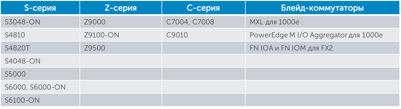
The table was updated in January 2016 due to the release of new products that support VLT.
Default Gateway with VLT
To protect the default gateway, you can configure the VRRP protocol within the VLT domain. In this case, both switches will route traffic sent to the default gateway, including the switch, which is not the current VRRP master.
An alternative to the VRRP protocol is Peer-routing functionality in the VLT domain. Consider how it works.
Packets from the server destined to the default IP gateway 10.10.10.2 (as shown in the diagram on the left), due to the hash algorithm for the LAG, can be forwarded to the Peer 1 switch. Without Peer-routing functionality, the switch will have to forward these packets to the Peer 2 switch .
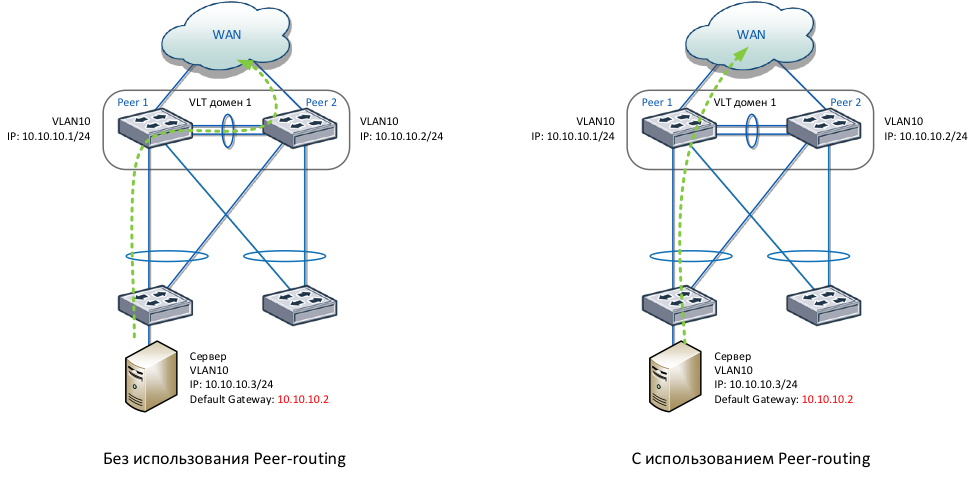
Peer-routing functionality allows the switch to forward packets to the default gateway located on the next VLT peer (as shown in the diagram on the right). Thanks to this, optimal routing is achieved, packets are delivered faster, the VLTi link does not load, and VRRP is not required to be configured. Peer-routing functionality protects the default gateway for more VLAN interfaces compared to VRRP, which has a limitation of 255 VLANs.
VLT Routing
In data center networks, it is important to provide a “stretched” Layer 2 domain for clustered applications and free migration of virtual machines. VLT technology provides such a “stretched” VLAN routing capabilities. This is achieved using the Peer-routing functionality, which in addition to the default gateway supports routing protocols OSPF, IS-IS and BGP. One of these protocols can be configured within a “stretched” VLAN on VLT switches. And then the neighbors using the routing protocol will be able to share their routes. In this case, only broadcast mode is supported for OSPF or IS-IS routing protocols, not point-to-point.
In data centers with high density of virtual machines for a given VLAN that is “stretched” across several racks, you can configure several default gateways and distribute them across switches in VLT domains. This will allow in turn to distribute ARP tables across VLT domains for greater scaling.
The VLT supports the IPv4 and IPv6 routing protocols, but Peer-routing functionality to protect the default gateway only works for IPv4. For IPv6 default-gateway protection, it is recommended to configure the VRRP protocol.
The diagram shows an example of using OSPF on a network with multiple VLT domains:

OSPF is configured on VLAN 10 interfaces in broadcast mode. For optimal propagation of routes, the VLT kernel-level switch, acting as the main (IP 10.10.10.1), is recommended to be designated as the DR for the OSPF, and its next VLT peer (IP 10.10.10.2) should be designated the BDR. On the main VLT peer for VLAN 10, you need to set the highest OSPF priority in order for this switch to be DR selected. On the adjacent VLT peer, a lower priority is set to select it as the BDR. After exchanging routes, all VLT switches have information through which next-hop addresses routes are available. At the same time, it is possible to “stretch” VLANs across all network switches, as shown in the example of VLAN 20 used for virtual machines.
Proxy Gateway for the neighboring VLT domain
Between the two VLT domains, you can configure the functionality of the Proxy Gateway. It allows you to locally route traffic destined for the default gateway from a neighboring VLT domain. This functionality is well suited for the case when two VLT domains are located in different geographically remote data centers. Proxy Gateway allows you to optimize packet flow between data centers, reduce channel loading between data centers and provide protection in case of failure of one of the VLT peers that act as the default gateway.
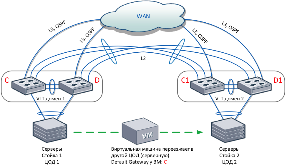
An example of the use of this feature is shown in the diagram. Remote VLT domains are interconnected by four physical links using dark fiber or DWDM. A virtual machine, with a configured default gateway C, migrates to a geographically remote data center without stopping its work. After moving to data center 2, the virtual machine will continue to work without reconfiguration. Packets sent by the virtual machine to gateway C will be locally routed by switches C1 and D1. If static routes are used on switches C and D, then you need to configure them on switches C1 and D1 for symmetric routing.
VLT setup example
Before you begin configuring, make sure that both switches in the VLT domain use the same version of the Dell Networking OS and that RSTP is configured. It will provide protection from loops if configuration errors are made.
In the following example, VLT peer 1 uses the hostname S4810-1, VLT peer 2 - the hostname S4810-2, and the Top-of-Rack switch - the hostname S60-1.

Configure VLTi between VLT peers. It is recommended to use for this static LAG:
Set the same VLT domain number on VLT peers:
Add a VLTi link inside the VLT domain configuration:
Configure backup connection between VLT peers. On VLT peer 1, use the IP address specified on the VLT peer 2 management interface for backup communication:
Assign the VLT to the peer 1 as the main role with the help of a lower priority than that of the neighbor:
Set the default MAC address for communication in the VLT domain:
Assign a unique unit ID (0 and 1) to each peer:
When you create a VLT domain on the switches, Dell Networking OS can assign the MAC address for the interaction itself and give the switches a unique unit ID. Using the system-mac mac-address and unit-id commands minimizes the synchronization time of peers after rebooting one of the switches.
Configure the VLT domain on peer 2:
We configure VLT connection of peers 1 and 2 with the Top-of-Rack switch. To do this, we configure LACP LAG on the ports of peers 1 and 2 connected to the Top-of-Rack switch. Set up the same VLT ID for this LACP LAG on VLT peers 1 and 2:
On the Top-of-Rack switch, we configure the LACP LAG for the physical ports connected to peers 1 and 2:
Check whether the VLT, the VLTi connection, the backup channel and the status of the neighboring VLT peer are working:
Check if VLT LAG is active on both VLT peers:
Design example
Consider an example of a data center network infrastructure design using VLT technology. Two VLT domains are connected by one LAG consisting of four 40GE ports. VLT allows you to distribute traffic across all channels between the level of blade switches and core network switches.
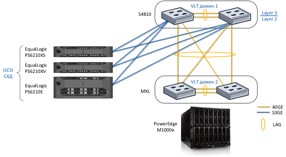
This network infrastructure also provides convergence of LAN and SAN networks by supporting iSCSI DCB technology on all components of the solution: Dell EqualLogic storage systems, Dell switches and converged adapters for Dell blade servers.
You can read more about this design example and its configuration described in the Datacenter Reference Architecture - Deploying Active fabric for Datacenter .
Usually, LAGs from servers and access level switches can be connected to only one aggregation level switch. To ensure fault tolerance, you can use the stack aggregation of several aggregation switches, which represent a single logical device. But this solution has its drawbacks, since the stack has a single control plane - it becomes the weak link of the system. When upgrading the operating system, all switches in the stack need to be rebooted, due to which service interruptions occur. Now let's compare this scheme with the one that uses VLT technology: this configuration already has two control planes, so the network continues to work even when updating the operating system on one of the switches. In this case, all the physical links between the switches assembled in the VLT and the devices connected to them are also duplicated.
All major manufacturers of network equipment have this kind of technology, each of which has its own proprietary implementation. For example, Cisco supports the Virtual Port Channel (vPC), Brocade uses Multi-Chassis Trunking (MCT), and Juniper supports the Virtual Chassis technology. Technologies are also used with open standards that provide similar functionality: Transparent Interconnection of Lots of Links (TRILL) and Shortest Path Bridging (SPB).
Main advantages of VLT
- no loops form in the Layer 2 domain;
- availability and fault tolerance;
- fast convergence in network failures;
- all physical channels in the network are active and used more efficiently;
- active load distribution on the default gateway using VRRP or Peer-routing functionality;
- fast convergence when rebooting one of the switches;
- Migration of virtual machines within a Layer 2 domain.
VLT Technology Description
VLT is a configuration of two switches, which on Layer 2 are perceived by other network devices as a whole. Physically, these are two devices that are interconnected according to a special scheme, but for servers, switches and other network devices, they look like a single switch. However, each of them has its own control plane, is configured independently of the other, and is controlled by its own operating system. Although a single network device connects to two switches using a LAG, VLT does not allow loops to form — the one that the Spanning Tree Protocol (STP) is struggling with. Such a connection provides fault tolerance and even load distribution between the switches. They can connect switches or stacks of switches, servers, or other devices that support the integration of multiple ports in a LAG using the LACP protocol.
')
Let's take the example of a small scheme in the terminology of the VLT, which we will need in the future.
- Virtual link trunk (VLT) is a virtual network link between connected devices and two VLT switches.
- VLT backup link is a backup connection that checks the performance of VLT switches. Through it, periodic keep alive packets are transmitted between VLT switches.
- VLT interconnect (VLTi) - a connection for transferring service information between VLT switches. These ports must be 10 Gbps or 40 Gbps.
- VLT domain - a domain of two VLT switches, VLTi ports and all VLT connections of devices connected to them. This domain is used for a single configuration of global VLT parameters.
- VLT peer is one of two VLT switches interconnected via VLT interconnect (VLTi).
- Non-VLT port — Any port on a VLT switch that has a device connected to it that is not connected to another VLT switch.
Periodic hello service messages are transmitted through the VLT backup connection, and VLT control messages through the VLTi interfaces. This is necessary to synchronize the L2 / L3 control plane between two VLT switches. MAC, ARP and IGMP tables are synchronized between them to provide joint switching and protection against failures if one of the switches or physical connection channels fails. VLT technology also provides forwarding traffic along the shortest path, bypassing the VLTi channel, but which can be used in the event of a failure.
The backup heartbeat packet exchange channel is usually provided through the control ports of the switches connected to a dedicated control network. Also, the backup channel can connect any ports of the VLT switches, but for heartbeat packets it is recommended to use the control port: it can work when the VLTi channel has failed.
In the VLT, one of the switches is chosen as the main switch, and it takes control of the LACP and STP protocols and sends service packets to the second VLT peer.
All VLANs configured for VLT connections are automatically added tagged for the VLTi channel.
Each device connected to a domain VLT receives broadcast packets through VLT switches only once. Broadcast packets are blocked when they are sent to the port of the connected device, if they are received by the VLT in peer via the VLTi link. But this only happens when the ports for the connected device are active at both peers. If a port on one of the peers does not work, then information about its status is immediately transmitted to the second peer. That, in turn, immediately removes the lock, and the device continues to receive packets.
Dell Switch Table with VLT Support
The table was updated in January 2016 due to the release of new products that support VLT.
Default Gateway with VLT
To protect the default gateway, you can configure the VRRP protocol within the VLT domain. In this case, both switches will route traffic sent to the default gateway, including the switch, which is not the current VRRP master.
An alternative to the VRRP protocol is Peer-routing functionality in the VLT domain. Consider how it works.
Packets from the server destined to the default IP gateway 10.10.10.2 (as shown in the diagram on the left), due to the hash algorithm for the LAG, can be forwarded to the Peer 1 switch. Without Peer-routing functionality, the switch will have to forward these packets to the Peer 2 switch .
Peer-routing functionality allows the switch to forward packets to the default gateway located on the next VLT peer (as shown in the diagram on the right). Thanks to this, optimal routing is achieved, packets are delivered faster, the VLTi link does not load, and VRRP is not required to be configured. Peer-routing functionality protects the default gateway for more VLAN interfaces compared to VRRP, which has a limitation of 255 VLANs.
VLT Routing
In data center networks, it is important to provide a “stretched” Layer 2 domain for clustered applications and free migration of virtual machines. VLT technology provides such a “stretched” VLAN routing capabilities. This is achieved using the Peer-routing functionality, which in addition to the default gateway supports routing protocols OSPF, IS-IS and BGP. One of these protocols can be configured within a “stretched” VLAN on VLT switches. And then the neighbors using the routing protocol will be able to share their routes. In this case, only broadcast mode is supported for OSPF or IS-IS routing protocols, not point-to-point.
In data centers with high density of virtual machines for a given VLAN that is “stretched” across several racks, you can configure several default gateways and distribute them across switches in VLT domains. This will allow in turn to distribute ARP tables across VLT domains for greater scaling.
The VLT supports the IPv4 and IPv6 routing protocols, but Peer-routing functionality to protect the default gateway only works for IPv4. For IPv6 default-gateway protection, it is recommended to configure the VRRP protocol.
The diagram shows an example of using OSPF on a network with multiple VLT domains:
OSPF is configured on VLAN 10 interfaces in broadcast mode. For optimal propagation of routes, the VLT kernel-level switch, acting as the main (IP 10.10.10.1), is recommended to be designated as the DR for the OSPF, and its next VLT peer (IP 10.10.10.2) should be designated the BDR. On the main VLT peer for VLAN 10, you need to set the highest OSPF priority in order for this switch to be DR selected. On the adjacent VLT peer, a lower priority is set to select it as the BDR. After exchanging routes, all VLT switches have information through which next-hop addresses routes are available. At the same time, it is possible to “stretch” VLANs across all network switches, as shown in the example of VLAN 20 used for virtual machines.
Proxy Gateway for the neighboring VLT domain
Between the two VLT domains, you can configure the functionality of the Proxy Gateway. It allows you to locally route traffic destined for the default gateway from a neighboring VLT domain. This functionality is well suited for the case when two VLT domains are located in different geographically remote data centers. Proxy Gateway allows you to optimize packet flow between data centers, reduce channel loading between data centers and provide protection in case of failure of one of the VLT peers that act as the default gateway.
An example of the use of this feature is shown in the diagram. Remote VLT domains are interconnected by four physical links using dark fiber or DWDM. A virtual machine, with a configured default gateway C, migrates to a geographically remote data center without stopping its work. After moving to data center 2, the virtual machine will continue to work without reconfiguration. Packets sent by the virtual machine to gateway C will be locally routed by switches C1 and D1. If static routes are used on switches C and D, then you need to configure them on switches C1 and D1 for symmetric routing.
VLT setup example
Before you begin configuring, make sure that both switches in the VLT domain use the same version of the Dell Networking OS and that RSTP is configured. It will provide protection from loops if configuration errors are made.
In the following example, VLT peer 1 uses the hostname S4810-1, VLT peer 2 - the hostname S4810-2, and the Top-of-Rack switch - the hostname S60-1.
Configure VLTi between VLT peers. It is recommended to use for this static LAG:
  s4810-1 (conf) #interface port-channel 100
 s4810-1 (conf-if-po-1) # channel-member TenGigabitEthernet 0 / 4-5
 s4810-2 (conf) #interface port-channel 100
 s4810-2 (conf-if-po-1) # channel-member TenGigabitEthernet 0 / 4-5
Set the same VLT domain number on VLT peers:
s4810-1 (conf) #vlt domain 1
Add a VLTi link inside the VLT domain configuration:
s4810-1 (conf-vlt-domain) # peer-link port-channel 100
Configure backup connection between VLT peers. On VLT peer 1, use the IP address specified on the VLT peer 2 management interface for backup communication:
  s4810-2 # show interfaces managementethernet 0/0
 Internet address is 10.11.206.58/24
 s4810-1 (conf-vlt-domain) # back-up destination 10.11.206.58
Assign the VLT to the peer 1 as the main role with the help of a lower priority than that of the neighbor:
s4810-1 (conf-vlt-domain) # primary-priority 100
Set the default MAC address for communication in the VLT domain:
s4810-1 (conf-vlt-domain) # system-mac mac-address 00: 11: 22: 33: 44: 55
Assign a unique unit ID (0 and 1) to each peer:
s4810-1 (conf-vlt-domain) # unit-id 0
When you create a VLT domain on the switches, Dell Networking OS can assign the MAC address for the interaction itself and give the switches a unique unit ID. Using the system-mac mac-address and unit-id commands minimizes the synchronization time of peers after rebooting one of the switches.
Configure the VLT domain on peer 2:
  s4810-2 (conf) #vlt domain 1
 s4810-2 (conf-vlt-domain) # peer-link port-channel 100
 s4810-2 (conf-vlt-domain) # back-up destination 10.11.206.43
 s4810-2 (conf-vlt-domain) # system-mac mac-address 00: 11: 22: 33: 44: 55
 s4810-2 (conf-vlt-domain) # unit-id 1
We configure VLT connection of peers 1 and 2 with the Top-of-Rack switch. To do this, we configure LACP LAG on the ports of peers 1 and 2 connected to the Top-of-Rack switch. Set up the same VLT ID for this LACP LAG on VLT peers 1 and 2:
  s4810-1 (conf) #interface TenGigabitEthernet 0/40
 s4810-1 (conf-if-te-0/40) # port-channel-protocol lacp
 s4810-1 (conf-if-te-0/40-lacp) # port-channel 1 mode active
 s4810-1 (conf) #interface port-channel 1
 s4810-1 (conf-if-po-1) #switchport
 s4810-1 (conf-if-po-1) # vlt-peer-lag port-channel 1
  s4810-2 (conf) #interface TenGigabitEthernet 0/40
 s4810-2 (conf-if-te-0/40) # port-channel-protocol lacp
 s4810-2 (conf-if-te-0/40-lacp) # port-channel 1 mode active
 s4810-2 (conf) #interface port-channel 1
 s4810-2 (conf-if-po-1) #switchport
 s4810-2 (conf-if-po-1) # vlt-peer-lag port-channel 1
On the Top-of-Rack switch, we configure the LACP LAG for the physical ports connected to peers 1 and 2:
  S60-1 (conf) #interface range TenGigabitEthernet 0/48, TenGigabitEthernet 0/50
 S60-1 (conf-if-range-te-0/48, te-0/50) # port-channel-protocol lacp
 S60-1 (conf-if-range-te-0/48, te-0/50-lacp) # port-channel 1 mode active
Check whether the VLT, the VLTi connection, the backup channel and the status of the neighboring VLT peer are working:
  s4810-1 # show vlt brief
  VLT Domain Brief
 ------------------
  Domain ID: 1
  Role: Primary
  Role Priority: 100
  ICL Link Status: Up
  HeartBeat Status: Up
  VLT Peer Status: Up
  Local Unit Id: 0
  Version: 6 (1)
  Local System MAC address: 00: 01: e8: 8b: 2d: 41
  Remote System MAC address: 00: 01: e8: 8b: 28: a9
  Configured System MAC address: 00: 11: 22: 33: 44: 55
  Remote system version: 6 (1)
  Delay-Restore timer: 90 seconds
Check if VLT LAG is active on both VLT peers:
  s4810-1 # show vlt detail
 Local LAG Id Peer LAG Id Local Status Peer Status Active VLANs
 ------------ ----------- ------------ ----------- ---- ---------
 1 1 UP UP 1
  s4810-1 # sho interfaces port-channel 1 brief
 Codes: L - LACP Port-channel
     LAG Mode Status Uptime Ports
 L 1 L2L3 up 00:34:00 Te 0/40 (Up)
Design example
Consider an example of a data center network infrastructure design using VLT technology. Two VLT domains are connected by one LAG consisting of four 40GE ports. VLT allows you to distribute traffic across all channels between the level of blade switches and core network switches.
This network infrastructure also provides convergence of LAN and SAN networks by supporting iSCSI DCB technology on all components of the solution: Dell EqualLogic storage systems, Dell switches and converged adapters for Dell blade servers.
You can read more about this design example and its configuration described in the Datacenter Reference Architecture - Deploying Active fabric for Datacenter .
Source: https://habr.com/ru/post/252763/
All Articles