Putting Wi-Fi robot
It has long dreamed of making a Wi-Fi robot that could be controlled remotely. And finally, the day came when I was able to control the robot via the Internet, to see and hear everything that happens around it.
Interested invite under the cat
The following components were used to create the robot:
')
Kit to build the robot platform
Robot controller board
Arduino Nano v.7
Engine driver
Nexx WT3020H Router
Mini USB 2.0 Hub
This is how the robot I assembled, without the top cover, looks like.

Now everything is in order:
Assembly of the robot platform:

The location of the components on the motherboard. I installed only Arduino Nano, the driver of the engines and the sound radiator HC:

Router wr703N attached to the bottom of the platform of the robot on double-sided tape:

The webcam is attached to the furniture corner, to the standard openings of the platform, provided for servomotors:

I patched the router with CyberWrt firmware .
CyberWrt is a firmware compiled on the basis of OpenWrt and intended primarily for robots, smart homes and other devices built on the basis of popular models of Tp-Link mr3020 b Wr703N routers. In CyberWrt, the maximum possible amount of free space for installing packages is 1.25 MB. By default, the web server is installed and all operations can be performed via the built-in web interface. Immediately after flashing, the router is available on the network via cable and WiFi, as an access point. Through the web interface, you can work in the "command line" mode - via a web terminal and in the file manager, where you can edit, download, delete, create, copy files and much more.
After the firmware of the router, it is available as a WiFi access point with the name “CyberBot”, we connect to it and go to the main page of the router. This is what the web interface looks like right after the firmware.
Installing modules FTDI Driver, Video driver and CyberBot-2.
We are flashing the arduino controller.
The program code of the robot turned out to be quite simple, but it is enough to remotely control the robot via a local network or the Internet.
The code is adapted for Arduino controllers with ATmega168 / 328 on board and uses the CyberLib library .
This library helps the controller to maximize its capabilities and reduce the amount of the final code.
The code uses WDT, so that the robot could not hang.
The same code supports camera control along the X and Y axes, but I did not have free servos and I could not use this function:
Code for Arduino
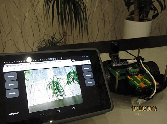
#include <CyberLib.h> #include <Servo.h> Servo myservo1; Servo myservo2; long previousMillis; http://cyber-place.ru/attachment.php?attachmentid=600&d=1389429469 uint8_t LedStep = 0; // int i; boolean light_stat; uint8_t inByte; uint8_t speed=255; // #define init {D4_Out; D5_Out; D6_Out; D7_Out; D8_Out; D11_Out; D12_Out;} void setup() { myservo1.attach(9); // myservo2.attach(10); // init; // D11_Low; // OFF randomSeed(A6_Read); // horn(); // UART_Init(57600);// wdt_enable (WDTO_500MS); } void loop() { unsigned long currentMillis = millis(); if (LedStep == 0 && currentMillis - previousMillis > 500){ // 0,5 . previousMillis = currentMillis; LedStep = 1; } if (LedStep == 1 && currentMillis - previousMillis > 500){ // 0,5 . previousMillis = currentMillis; LedStep = 2; } if (LedStep == 2 && currentMillis - previousMillis > 500){ // 0,5 . LedStep = 0; } if (UART_ReadByte(inByte)) // { switch (inByte) // { case 'x': // robot_stop(); break; case 'W': // robot_go(); break; case 'D': // j robot_rotation_left(); break; case 'A': // robot_rotation_right(); break; case 'S': // robot_back(); break; case 'U': // myservo1.write(i -= 20); break; case 'J': // myservo1.write(i += 20); break; case 'H': // myservo2.write(i += 20); break; case 'K': // myservo2.write(i -= 20); break; case 'B': // D12_High; break; case 'C': // horn(); break; case 'V': // / if(light_stat) { D8_Low; light_stat=false; } else { D8_High; light_stat=true; } break; } if(inByte>47 && inByte<58) speed=(inByte-47)*25+5; // } wdt_reset(); } void horn() { for(uint8_t i=0; i<12; i++) beep(70, random(100, 2000)); // } void robot_go() { D4_Low; analogWrite(5, speed); analogWrite(6, speed); D7_Low; } void robot_back() { D4_High; analogWrite(5, 255-speed); analogWrite(6, 255-speed); D7_High; } void robot_stop() { D4_Low; analogWrite(5, 0); analogWrite(6, 0); D7_Low; } void robot_rotation_left() { D4_Low; analogWrite(5, speed); analogWrite(6, 255-speed); D7_High; } void robot_rotation_right() { D4_High; analogWrite(5, 255-speed); analogWrite(6, speed); D7_Low; } Everything is assembled and stitched, now we turn on the robot and control it remotely.
On the PC, in addition to the on-screen buttons, you can control it from the keyboard, using the W, A, D, S, X keys
I post the video:
In the future, I plan to teach the robot to navigate in space and draw a map of the room.
Source: https://habr.com/ru/post/252411/
All Articles