Automatic identification of electronic components
Very interesting and simple device that will measure the resistance, capacitance and inductance of any element in a few seconds.
This will require very few details that each arduinschik beginner usually has: an ATMEGA microcontroller, a two-line display and several resistors.
This device was developed by Marcus Frejek (the final version of the project in German ), and then, to this day, Karl-Heinz Kubbeler has been finalizing (the current project page is in German ).
')
Despite the fact that this project is positioned as a transistor tester, I am much more interested in its ability to quickly measure two-pin components, hence the name of the article.
Full list of device features:
Fully automatic detection of the following components:
- resistors with resistance
- capacitors indicating capacity
- inductance with indication of resistance and inductance
- Diodes with anode, cathode and voltage drop
- bipolar and field effect transistors with indication of the BKE and PPE
- thyristors and triacs with indication of the conclusions of the spacecraft UE
You can buy it as an assembled device or as a constructor for assembly, but the most interesting thing is that you can assemble it yourself on a breadboard for half an hour from parts that are often already at hand.
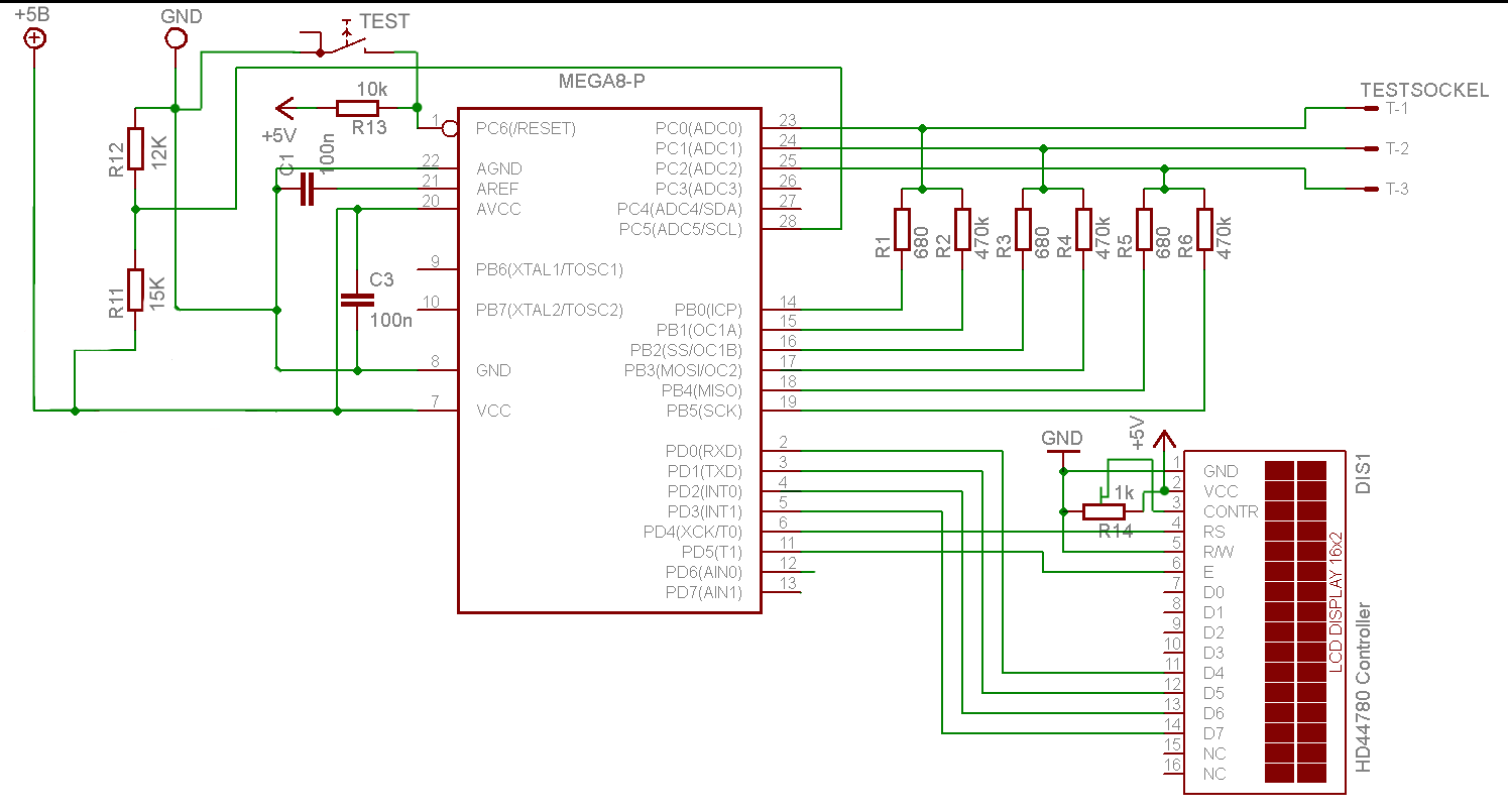
The most simplified scheme for quick assembly:
The latest firmware is currently here . You only need to select a subdirectory for a particular microcontroller model.
Unfortunately, if you use ATMEGA8A, you will either overestimate the resistance measurement by 1.5 times, or decrease the capacity measurement by 1.5 times, and you will need firmware specifically for 8A, you can find it here , ATmega8A_Engl.zip. And it is better to immediately find and use ATMEGA328P.
Detailed technical documentation in Russian is available here . In the directory you need to select the file ttester.pdf. (At the bottom of the page click “Download GNU tarball”, unpack the archive and find the PDF you need.)
It looks, of course, untidy, but it is already working.
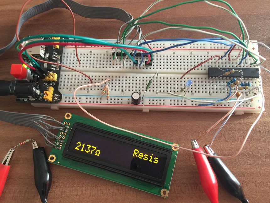
The accuracy of the measurement is still low, but even in this form it is just a wonderful device, which I will definitely do in the case and settle on my desk.
To improve the accuracy of measurements, I plan to approach the reference scheme in the following steps:
- Change the measuring resistors to more accurate with a deviation of 1%.
- Add quartz to 8 MHz.
- Put the ion
- Transfer to the solder board with a minimum length of conductors.
- Go to ATMEGA328.
These components are on the way, on arrival I will update the article with the results.
UPDATE 1
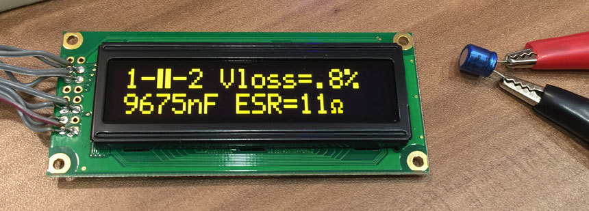
Components arrived, replaced ATMEGA8A with ATMEGA328P, inductance and ESR of capacitors were determined. Updated KDPV.
After replacing the MK, measurements began to take much longer, after the measurement the message TimeOut began to appear! and the screen was turned off after a couple of seconds. According to the instructions, I connected a 10K resistor from the power supply to pin 13, everything began to work normally.
I replaced the resistors by 1% (unfortunately I did not manage to buy 0.1%, as recommended in the instructions). The definition of resistors has improved, but it's still rude.
Found 1% resistors of different ratings and measured them.
Here are the ratings, the measurement results of the DT-838 multimeter (claimed measurement accuracy of 1%) and the collected circuit (after the recommended calibration):
82.5 ohm - 92.3 ohm - 96.8 ohm
392 ohm - 390 ohm - 426 ohm
649 ohm - 640 ohm - 693 ohm
499 ohm - 497 ohm - 510 ohm
1k - 1001 ohm - 987 ohm
4.27k - 4.27k - 4.274 ohm
4.75k - 4.75k - 4707 ohm
13.3k - 13.28k - 13.04k
22.6k - 22.5k - 22.1k
1.65k - 1698 ohm - 1620 ohm
1m - 1014k - 996 k
10m - out of range - 8783k
20m - out of range - 17.83m
I am glad of the possibility of determining such enormous resistances.
Source: https://habr.com/ru/post/252321/
All Articles