Big pitfalls of a small controller
This publication is the answer to frequently asked questions about the ATtiny4 / 5/9/10 microcontroller family. Most of them are solved by careful reading of the documentation. Nevertheless, I decided to describe the main differences in working with these MCs. Under the cat you will find a story about the youngest AVRs, as well as a description of the problems that appear when meeting them.
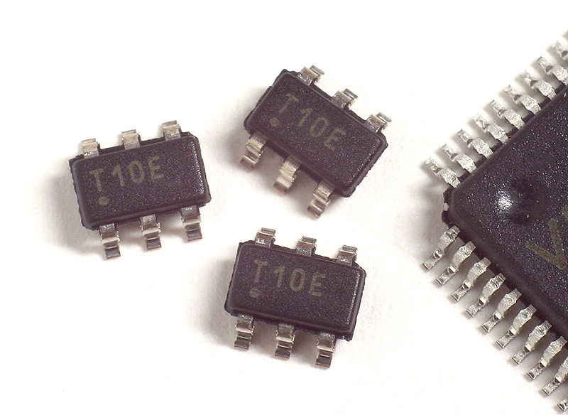
These controllers belong to the tinyAVR family, like the popular ATtiny85, however, they are significantly different from the rest. First, only ATtiny4, 5, 9 and 10 are packaged in a small, but easily soldered SOT23-6. Secondly, the TPI interface is used for programming, which is incompatible with the traditional ISP. Thirdly, these are the only tinyAVRs, the clocking source of which can be switched on the fly, which makes them more modern.
The senior member of the family, ATtiny10, appeared in 2009 and can be easily purchased from most suppliers.
')
Microcontrollers in the SOT23-6 package are interesting in small size, they occupy about 9 sq. Mm. Only "lead-free" enclosures that are incomparably more difficult to install and often require multilayer boards can indulge with this indicator.
In addition to Atmel, Microchip has controllers in this package. However, the PIC10F2xx are inferior in performance, and the hybrid PIC10F3xx have less program memory, although they have programmable logic on board and they are much more economical.
I made a comparative table of some MK of these families, consumption is indicated on MHz in active and sleep modes.
The table does not specify the size of the EEPROM, because it is not.
The cost of Atmel products is in the range of 58-72 cents in a batch of 1000 pieces. PIC is slightly cheaper from 46 to 75 cents, but getting them in the SOT23-6 package is not so easy. In local stores, all of these MKs can be bought for as low as 70–80 rubles per piece.
Given the more powerful AVR assembler, my choice is definitely leaning toward them. Although the PIC10F3xx looks pretty good, I haven’t worked with them yet.
At acquaintance c ATtiny10 microcontrollers there are several problems. Here are the 5 most common.
This is especially evident in C programs, so examples will be on it.
The clocking system of this family has a number of differences from other AVRs. Since there are no corresponding fuses, their functions are performed by 3 registers: CLKMSR, CLKPSR and, pay special attention - CCP.
After reset, the controller always runs from an internal 8 MHz source and has a limiter 8. To switch to another source, you must change the contents of CLKMSR, and change the limiter - CLKPSR. What you can do with them is written in tables 6-3 and 6-4 datasheet.
The fact is that the construction of the following type does not have the expected effect:
This is discouraging for some, but the registers responsible for clocking are write-protected.
To change their contents, it is necessary to record the value 0xD8 in CCP , this will give 4 clocks to work with these registers, and during these 4 clocks any interrupts are ignored.
Correctly do so:
Such assignment expressions are usually executed in two cycles. However, less efficient code may be generated. In the event of such a problem, it makes sense to write CCP before each change in the protected register, surrounding the construction group with a ban on interrupts.
The “doggie” mode is selected via the WDTCSR register, which is also protected by the CCP register. I think there are no comments here.
Like other AVR microcontrollers, the reset input can be switched to I / O port mode. The ability to flash the controller with a sequential programmer is lost. The family is interesting because to solve this problem, it is enough to apply 12 volts to the RESET during the entire programming time, having previously disconnected this line from the programmer.
Those who use this family for the first time have a very frequent problem. Usually, the point is the supply voltage, the TPI interface through which these controllers are stitched, works only with a power of 5 volts, and the corresponding logic levels of the programmer.
The family in question has very few fusions left.
Half fit in the low byte at 0x00. These are RSTDISBL — a power-off reset, WDTON — a enable watchdog, and CKOUT — an output signal with a clock frequency to port PB2.
Lock Byte, necessary for protection against programming and reading the memory of the controller, remained in its place.
Despite seeming weakness, ATtiny10 can not only flash LEDs or transform interfaces. Later, I will talk about USB software for these tiny controllers.
These controllers belong to the tinyAVR family, like the popular ATtiny85, however, they are significantly different from the rest. First, only ATtiny4, 5, 9 and 10 are packaged in a small, but easily soldered SOT23-6. Secondly, the TPI interface is used for programming, which is incompatible with the traditional ISP. Thirdly, these are the only tinyAVRs, the clocking source of which can be switched on the fly, which makes them more modern.
The senior member of the family, ATtiny10, appeared in 2009 and can be easily purchased from most suppliers.
')
Microcontrollers in the SOT23-6 package are interesting in small size, they occupy about 9 sq. Mm. Only "lead-free" enclosures that are incomparably more difficult to install and often require multilayer boards can indulge with this indicator.
In addition to Atmel, Microchip has controllers in this package. However, the PIC10F2xx are inferior in performance, and the hybrid PIC10F3xx have less program memory, although they have programmable logic on board and they are much more economical.
I made a comparative table of some MK of these families, consumption is indicated on MHz in active and sleep modes.
| Title | Flash byte | Ram, byte | Clocking | ADC | Analog comparator | AND HE | Timer | Nutrition, AT | Consumption |
|---|---|---|---|---|---|---|---|---|---|
| ATtiny4 | 512 | 32 | 8 MHz 128 kHz | - | + | - | 1, 16 bits 2 PWM channels | 1.8 - 5.5 | 200 mA <0.1 µA |
| ATtiny5 | 512 | 32 | 8 MHz 128 kHz | 1, 8 bits 4 channels | + | - | 1, 16 bits 2 PWM channels | 1.8 - 5.5 | 200 mA <0.1 µA |
| ATtiny9 | 1024 | 32 | 8 MHz 128 kHz | - | + | - | 1, 16 bits 2 PWM channels | 1.8 - 5.5 | 200 mA <0.1 µA |
| ATtiny10 | 1024 | 32 | 8 MHz 128 kHz | 1, 8 bits 4 channels | + | - | 1, 16 bits 2 PWM channels | 1.8 - 5.5 | 200 mA <0.1 µA |
| PIC10F206 | 768 | 24 | 4 MHz | - | + | + | 1, 8 bits No pwm | 2 - 5.5 | <175 μA 0.1 μA |
| PIC10F222 | 768 | 23 | 8 MHz 4 MHz | 1, 8 bits 2 channels | - | + | 1, 8 bits No pwm | 2 - 5.5 | <175 μA 0.1 μA |
| PIC10F320 | ~ 460 | 64 | 16 MHz 32 kHz | 1, 8 bits 3 channels | - | + | 2, 8 bits Have pwm | 1.8 - 3.6 2.3 - 5.5 | 25 μA 0.02 µA |
| PIC10F322 | ~ 920 | 64 | 16 MHz 32 kHz | 1, 8 bits 3 channels | - | + | 2, 8 bits Have pwm | 1.8 - 3.6 2.3 - 5.5 | 25 μA 0.02 µA |
The table does not specify the size of the EEPROM, because it is not.
The cost of Atmel products is in the range of 58-72 cents in a batch of 1000 pieces. PIC is slightly cheaper from 46 to 75 cents, but getting them in the SOT23-6 package is not so easy. In local stores, all of these MKs can be bought for as low as 70–80 rubles per piece.
Given the more powerful AVR assembler, my choice is definitely leaning toward them. Although the PIC10F3xx looks pretty good, I haven’t worked with them yet.
At acquaintance c ATtiny10 microcontrollers there are several problems. Here are the 5 most common.
1. Clock does not switch
This is especially evident in C programs, so examples will be on it.
The clocking system of this family has a number of differences from other AVRs. Since there are no corresponding fuses, their functions are performed by 3 registers: CLKMSR, CLKPSR and, pay special attention - CCP.
After reset, the controller always runs from an internal 8 MHz source and has a limiter 8. To switch to another source, you must change the contents of CLKMSR, and change the limiter - CLKPSR. What you can do with them is written in tables 6-3 and 6-4 datasheet.
The fact is that the construction of the following type does not have the expected effect:
CLKPSR = (1<<CLKPS2); This is discouraging for some, but the registers responsible for clocking are write-protected.
To change their contents, it is necessary to record the value 0xD8 in CCP , this will give 4 clocks to work with these registers, and during these 4 clocks any interrupts are ignored.
Correctly do so:
CCP = 0xD8; CLKMSR = (1<<CLKMS0); CLKPSR = (1<<CLKPS0); Such assignment expressions are usually executed in two cycles. However, less efficient code may be generated. In the event of such a problem, it makes sense to write CCP before each change in the protected register, surrounding the construction group with a ban on interrupts.
2. Watchdog issues
The “doggie” mode is selected via the WDTCSR register, which is also protected by the CCP register. I think there are no comments here.
3. Putting RESET into GPIO mode
Like other AVR microcontrollers, the reset input can be switched to I / O port mode. The ability to flash the controller with a sequential programmer is lost. The family is interesting because to solve this problem, it is enough to apply 12 volts to the RESET during the entire programming time, having previously disconnected this line from the programmer.
4. The controller is not programmed, does not seem to programmer.
Those who use this family for the first time have a very frequent problem. Usually, the point is the supply voltage, the TPI interface through which these controllers are stitched, works only with a power of 5 volts, and the corresponding logic levels of the programmer.
5. Where are the fusions?
The family in question has very few fusions left.
Half fit in the low byte at 0x00. These are RSTDISBL — a power-off reset, WDTON — a enable watchdog, and CKOUT — an output signal with a clock frequency to port PB2.
Lock Byte, necessary for protection against programming and reading the memory of the controller, remained in its place.
Despite seeming weakness, ATtiny10 can not only flash LEDs or transform interfaces. Later, I will talk about USB software for these tiny controllers.
Source: https://habr.com/ru/post/251919/
All Articles