The quality of data networks. Transport
In the previous article the basic metrics of the quality of networks and data transmission systems were touched upon. It was also promised to write about how everything works from the inside. And intentionally it was not mentioned about the quality of the data transmission medium and its characteristics. I hope that the new article will provide answers to these questions.
Transmission medium
I will begin, perhaps, with the last point - the quality of the transmission medium. As already written above, nothing was said about it in the previous narrative, since the number of mediums and their characteristics themselves are very different and depend on just a huge number of factors. Understanding all this diversity is the task of the relevant specialists. It is obvious to all that radio airtime is used as a transmission medium. I remember in the late 90s and early 00s, such exotic transmission methods as laser atmospheric transmitters began to be particularly popular with telecom operators.
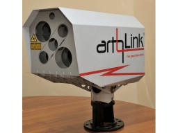 They looked, depending on the manufacturer and configuration, something like the picture on the left (yes, almost such a light phone from amateur radio). Their advantage was that it was not necessary to obtain the permission of the HMLR , and even the speeds were slightly higher compared to the radio bridge, besides, there were modifications for the organization of time-division channels (E1, etc.), and similar equipment access was cost prohibitively expensive. Why not an optical cable? Because in those happy times of wild providing, optics were still quite expensive, and for an interface converter or active equipment that could receive an optical link directly gave a small (and some large) bar of gold. There were also satellite channels, but this is generally from the realm of fantasy and could afford them only if the companies of the oil sector and other national wealth. But the work of the channel via satellite is reduced to the use of radio-air, with all the consequences and the introduction of a huge delay.
Accordingly, plunging into the question as a result, we will have a lot of media and not a single generalized characteristic. Nevertheless, for us the environment is just a transport, transmitting information from point A to point B. And for transport (even public), the characteristic reflecting its quality will be the delivery of all bits (well, or passengers) without distortion and loss (I would not want to lose some body during transportation, agree). Those. we come to such a generalized metric of transport quality as the number of bit errors, or BER (Bit error rate). In purely packet networks, it is practically not used, since transmission errors are detected at the packet level, for example, the calculation of checksums: FCS (Frame check sequence) for L2 or hecksum IP for L3. If the checksum does not match, then the entire packet is discarded as invalid. If we consider heterogeneous networks, those in which a non-packet network can serve as transport, and, for example, one of the options described above, or transit through ATM , PDH , SDH and the like is used without the direct (but with recovery) packet transmission, then bit errors transport can greatly influence, of course, depending on the technology. Consider the encapsulation and transmission of an Ethernet frame in HDLC. Other technologies use almost the same technique.
')

The scheme is read from left to right (taken here ).
- Some node of network A sends a packet towards some node of network B
- Transport between networks is built on a PDH network.
- The node at the exit edge of network A cuts out the payload area from the Ethernet frame (fields from DestinationAddress to FCS inclusive), wraps the headers in HDLC, and sends it to the border node of network B input
- Network B input node allocates payload area and recovers Ethernet frame
- The frame from the border node is sent to the recipient
As you can see, in this case, the control is transmitted correctly and in the event of a bitstream damage during transmission, the recovered packet with the wrong FCS will be discarded by the receiver. In this case, the error detection mechanism is obvious.
But the add-in encapsulation is not always used, or the full frame is not transmitted at all, but only the payload field. Those. an area is cut, wrapped in an internal protocol, and missing data is restored on the other side, including missing L2 headers. Accordingly, FCS also disappears - it is simply calculated anew. Thus, it turns out that if the data was damaged and the FCS was calculated on the basis of the “corrupted” data, the recipient does not receive the package that was sent to him. This is quite common in satellite communications in order to increase the useful utilization of the channel, while avoiding the transfer of conditionally “extra” information. Summarizing, it turns out that the BER metric may be interesting in cases where:
- it is necessary to check the stability of the physical channel, for example for optics it is 10E-12 (mentioned in IEEE802.3)
- Ethernet frames are packaged in SDH (GFP), PDH, ATM, and other transport networks.
- xHSL, PPP protocols are used in which IP packets are packed
Ber test
The metric known is the ratio of the number of bit errors to the total number of bits transmitted. The measurement technique for TDM networks is known as the ITU-T G.821 specification. Classically, BERT (BER Test) of the first level is used to test channels, but taking into account the specifics of the packet network encapsulation protocols and the very principle of packet networks, it is necessary to be able to perform tests on L1-L4. A little further will be discussed in more detail. Well, now you should decide what to check and how to check. To the question: “What to check?” ITU-T 0.150 answers. In its paragraph 5, the types of PSPs (pseudo-random sequences) are considered, from which the data for the formation of a packet are simply taken. Those. you just need to take and fill the appropriate packet level with the data of the selected SRP. We use the following devices in our devices:
- PSP 2e9 (ITU-T 0.150 clause 5.1)
- PSP 2e11 (ITU-T 0.150 clause 5.2)
- PSP 2e15 (ITU-T 0.150 clause 5.3)
- PSP 2e23 (ITU-T 0.150 clause 5.6)
- PSP 2e31 (ITU-T 0.150 clause 5.8)
- custom sequence (32 bits)
- all zeros
- all units
- alternative sequence (01010101)
Custom sequence is introduced for compatibility with devices that exist on the market, that is, you can specify any sequence and conduct a joint test.
The question how to check is still open, let's try to figure it out. Suppose we can generate certain packages. If you send such a packet to the other end of the transport, how can you understand that it has not changed (we should abstract from the packet principle, since we may not have FCS and other types of controls, as described earlier)? The easiest option is to wrap the packet back (in TDM is called “loop”, on Ethernet it is to install a loop). Inversion, in many cases, can be done at the channel output without changing the transmission medium, i.e. really put a loop on the output of E1 and everything will work. But since Since the data makes a double path, the probability of an error also increases by 2 times. And the channels can be asymmetric or unidirectional. Accordingly, it would be ideal to be able to have information about the correct following and to compare incoming packets with already known information. The first, and simplest option, applicable when both channel outputs are located side by side (for example, this is possible with TDM switching, or testing an optical “ring”) is that one port of the device generates test traffic, and the other port of the same device receives it and compares, and since Since the comparison occurs in the same node as the generation, then there are no problems with comparing the sequence data. The second option involves the restoration of the original sequence and comparing it with incoming data. In the case of a completely random sequence, it is not possible to realize this, but if the sequence is pseudo-random, then completely. Some time is spent on synchronization at the very beginning of the test, but then the comparison is not difficult. Since the PSP of the first device and the PSP of the second are known and identical, synchronization is reduced to finding the place where the comparison starts in the PSP of the second device. Therefore, the following topologies exist:
- "On myself" 1 - one device on one port, on the other end of the transport there is a loop
- "On itself" 2 - one device from one port of its port to another port
- from one device to another device, with synchronization
- Ethernet frame is formed containing PSP data
- for such a frame is calculated FCS and it fits into the output buffer
- frame is sent over the network to another device
- for some reason, only a single bit within the packet is changed
- the receiver accepts the package
- FCS received packet does not match the content
- the packet is discarded (if there is, for example, a switch between the sender and the receiver, then the packet will not reach the receiver at all, since it will be destroyed to it)
- the sender forms the next packet (it all starts with step 1)
In the example shown in step 8, synchronization will be disrupted on the recipient side. It will happen because the sender will take the next block of the SRP, and the recipient will compare with the block that was lost in the previous cycle (he does not know anything about the loss). A synchronization failure will lead to an unreasonably large increase in bit errors, since all the new blocks do not coincide at all, which will lead to the fact that in one packet the number of bit errors will increase by the frame size. After some time, an attempt will be made to restore synchronization, but the number of accumulated bit errors will be much inconsistent with reality.
And how in the gland?
Like others, I don’t know, but with our Berkut instruments ( ET , ETX , ETL , B100 , as well as the B5-GBE module for MMT ), the situation is as follows. Remembering the principle of generating and analyzing traffic as close as possible to the physical segment from the first article, all such tasks were assigned to FPGA. A simplified structural diagram looks like this:

The MAC core is represented by two blocks: one for reception, the other for transmission. This allows you to independently receive and send packets, i.e. There is no interaction between the send queue and the receive queue, and vice versa. It is also possible to keep general statistics on the received and sent traffic from two independent blocks regardless of the type of test. The data from the transmission unit is received by the transmitter and sent to the network, and the incoming data from the transceiver is received by the reception unit.
Since some test topologies require loop functionality (loopback, loop), it is implemented in a separate unit. It is possible to install a loop of level L1-L4:
- L1 - just wraps traffic back (it happens in the transceiver)
- L2 - changes DstMAC <-> SrcMAC in places, recounts FCS
- L3 - changes DstMAC <-> SrcMAC and DstIP <-> SrcIP in places, recalculates FCS
- L4 - changes DstMAC <-> SrcMAC, DstIP <-> SrcIP and DstPort <-> SrcPort, recounts FCS
The statistics on the packets is maintained for the loop mode too, which makes it possible to roughly estimate the ratio of sent and received packets.
The generator module for each type of test is different; for BERT, it contains a generator of the memory bandwidth of all declared types.
It works as follows. From the PSP generator, data is sent to a multiplexer (in other words, a switch), which, if no other channel is currently on, sends the stream to the MAC tx module. The MAC tx module, in accordance with the test settings (BERT level, packet size, field data), forms a valid Ethernet frame from the SRP and sends it to the transceiver, which in turn sends it to the network. Depending on the topology of the test, the frame is either wrapped by the remote side or analyzed. In any case, the initial processing of the package is no different. The frame falls on the MAC rx core, which sends it to the multiplexer. Depending on the device operation mode, the multiplexer sends the packet either to the Loopback module, from where it is sent after processing to the MAC tx for sending, or to the processing and test statistics module, where, if necessary, it will attempt to synchronize the memory bandwidth and compare the original sequence with received. Processing results are sent to the statistics output module.
Using FPGA or ASIC allows all operations to be performed in parallel, which does not introduce any processing delays and eliminates the interference of the processing modules.
Conclusion
Despite all the seeming simplicity of algorithms and techniques, there are many years of serious research behind them. A huge number of factors still affect both the accuracy of measurements and the cost of devices (precision elements, high-speed FPGAs). For example, the above BER test is not very complex in general algorithmic terms, but requires knowledge of mathematics, computer science and information theory for the development of a viable model. Modifying the BER test for packet networks (supporting L2-L4 levels) requires a deep understanding of switching and routing principles. I hope that this kind of articles are interesting and useful. In the following publications I plan to write about certified tests, traffic generators, filters and analytical systems. After all, as John Fitzgerald Kennedy said at a speech before US citizens before the start of the lunar program:
“And we will do it. Not because it is easy, but because it is difficult. ”
Ps. Ask questions and suggest topics, within our competence are ready for anything :)
Source: https://habr.com/ru/post/251693/
All Articles