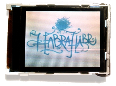
Understanding the LCD screen LPH9157-2 from Siemens C75 / ME75
I did not find any clear documentation for this screen, so I had to deal with the fact that I had to experiment. I used the Raspberry PI as a control device. Also, a program was written that allows you to turn this screen into a mini-monitor.
Description
This display has a resolution of 132 x 176 pixels and allows you to work with three color palettes of 16 (5-6-5), 12 (4-4-4) and 8 (3-3-2) bits.
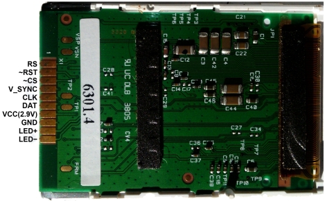
Pinout and connection
Everything is simple, the screen is powered by a voltage of 2.9 volts, the backlight (LED ±) is powered separately by about 12 volts (I used a battery connected to the backlight through a 510 ohm resistor).
| Pin description | ||
|---|---|---|
| # | Name | Function |
| one | RS | Low = CMD, High = DATA |
| 2 | ~ RST | Reset input active low |
| 3 | ~ CS | Chip select, active low |
| four | SYNC | External frame synchorization input, unused by default |
| five | CLK | SPI Clock-in signal (High-to-Low) |
| 6 | DATA | SPI Data-in signal (MSB first) |
| 7 | VCC | Power supply, normally 2.9V (I tested with 3.3V) |
| eight | GND | Ground |
| 9 | LED + | Backlight voltage, approx. 12V (depends on required current) |
| ten | LED- | Backlight common pin |
And before you go directly to the management of the screen, you would need to connect this screen to something. In my case it will be Raspberry Pi. The screen SPI contacts are connected to their corresponding SPI raspberry, RS, and RST pins to GPIO_17 and GPIO_27, respectively. This connection is relevant for RPI Revision-2, if you have a different model, the names and numbers of GPIO contacts may differ.
 | 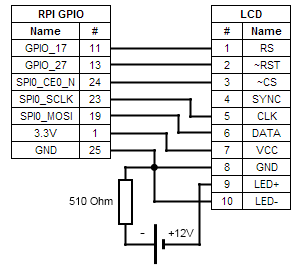 |
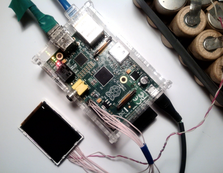
I did not bother with the screen connection connector and just soldered to the terminals with MGTF wire. The screen in this connection is powered by 3.3V, and not from 2.9 as in the description.
This is what the whole assembly looks like.
')
Screen control commands
The screen is controlled quite simply - by sending SPI commands and data. The status of the RS pin helps to distinguish one from the others, where a high level (log. 1) means data transfer, and a low level (log. 0) sends commands. The transfer uses a blunt (big-ending) byte order.
List of commands:
- CMD_RESET 0x01 - soft reset
- CMD_MEMORY_ACCESS_CONTROL 0x36 - setting the fill direction of the display area, has a one-byte argument 0bVHRXXXXX, where
V - filling vertically (0 - top-down, 1 - bottom-up),
H - filling horizontally (0 - from left to right, 1 - from right to left),
R - swap rows and columns (with the filling remains top-down, left-to-right)) - CMD_WAKEUP 0x11 - wake from sleep mode
- CMD_PALETTE 0x3A - setting the color palette 8 (0x02), 12 (0x03) and 16 (0x05) bits
- CMD_ENABLE 0x29 - display on
- CMD_SET_X 0x2A - set the drawing area on X
- CMD_SET_Y 0x2B - set the drawing area by Y
- CMD_START_WRITE 0x2C - start recording to video memory
Code
The screen was tested in all 3 color modes, but in order not to clutter up the source, then I will consider only 16-bit. In all other modes, the screen does not differ, except, perhaps, 12-bit - there are 3 bytes per 2 pixels, and if you only need to output one point, 2 bytes are sent (the last 4 low bits of the screen are ignored).
To access the raspberry GPIO, the bcm2835 library was used.
GPIO Initial Initialization
int init_gpio() { if (!bcm2835_init()) return 0; bcm2835_spi_begin(); bcm2835_spi_setBitOrder(BCM2835_SPI_BIT_ORDER_MSBFIRST); // CPOL = 0, CPHA = 0, Clock idle low, data is clocked in on rising edge, output data (change) on falling edge bcm2835_spi_setDataMode(BCM2835_SPI_MODE0); // SPI 13 // // (30 ) bcm2835_spi_setClockDivider(BCM2835_SPI_CLOCK_DIVIDER_16); ///< 16 = 64ns = 15.625MHz bcm2835_spi_chipSelect(BCM2835_SPI_CS0); /// Select Our Device bcm2835_spi_setChipSelectPolarity(BCM2835_SPI_CS0, LOW); // bcm2835_gpio_fsel(LCD_RS, BCM2835_GPIO_FSEL_OUTP); bcm2835_gpio_fsel(LCD_RESET, BCM2835_GPIO_FSEL_OUTP); return 1; } Several auxiliary functions
void send_cmd(char cmd) { bcm2835_gpio_write(LCD_RS, RS_CMD); // - bcm2835_spi_transfer(cmd); } void send_data(char data) { bcm2835_gpio_write(LCD_RS, RS_DATA); // - bcm2835_spi_transfer(data); } Set the drawing area
void set_draw_area(char x1, char y1, char x2, char y2) { send_cmd(CMD_SET_X); send_data(x1); send_data(x2); send_cmd(CMD_SET_Y); send_data(y1); send_data(y2); } As a result of experiments with the screen, it turned out that it is not necessary to specify the area before outputting each frame, it is enough to set it only once and sending the command to start recording just drive a sequence of frames on the SPI in a continuous stream.
Preparing for the withdrawal and data transfer
void draw_start() { send_cmd(CMD_START_WRITE); bcm2835_gpio_write(LCD_RS, RS_DATA); } void send_draw_data(char* data, int size) { bcm2835_spi_transfern(data, size); } In the process of screen initialization, an annoying thing was discovered - to launch it is necessary to turn the RESET screen back on, but subsequent manipulations with this output lead the screen to a stupor and it stops responding to external influences. You have to dump it on nutrition. This should be taken into account when developing a program so that the hardware reset procedure was performed only once.
Screen initialization
void reset_LCD() { // bcm2835_gpio_write(LCD_RESET, LOW); bcm2835_delay(50); bcm2835_gpio_write(LCD_RESET, HIGH); bcm2835_delay(50); // send_cmd(CMD_RESET); } void init_LCD() { reset_LCD(); send_cmd(CMD_MEMORY_ACCESS_CONTROL); send_data(0b00000000); send_cmd(CMD_WAKEUP); bcm2835_delay(20); send_cmd(CMD_PALETTE); send_data(_16_BIT_COLOR); bcm2835_delay(20); send_cmd(CMD_ENABLE); } It was a preparation, and now the most delicious - let's try to display a 16-bit image on the screen. The first pancake is known to be a lump, after launching the program I received a rather strange image, it turned out - the wrong order of bytes, after the fix it all worked.
Code
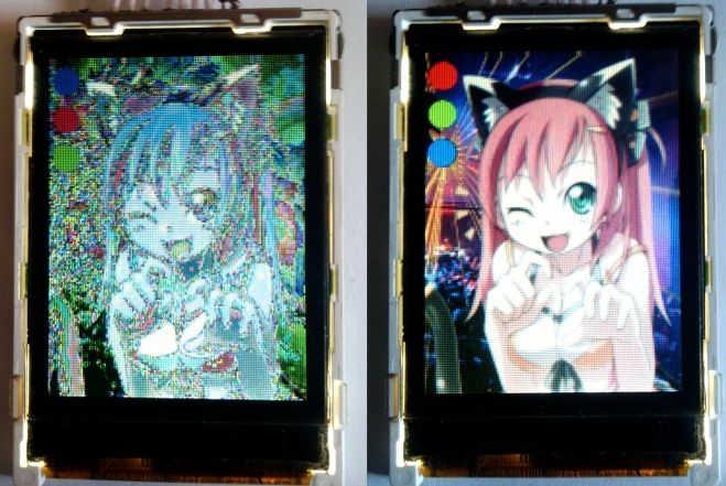
int main(int argc, char **argv) { if (!init_gpio()) return 1; init_LCD(); set_draw_area(0, 0, SCREEN_WIDTH - 1, SCREEN_HEIGHT - 1); draw_start(); uint16_t screen[SCREEN_HEIGHT][SCREEN_WIDTH]; FILE* f_scr = fopen("test.bmp", "r"); fseek(f_scr, 0x42, SEEK_SET); // skip bmp header fread(&screen, 1, SCREEN_HEIGHT * SCREEN_WIDTH * 2/*16bit*/, f_scr); fclose(f_scr); // change byte order for(int x = 0; x < SCREEN_WIDTH; x++) for(int y = 0; y < SCREEN_HEIGHT; y++) screen[y][x] = (screen[y][x] >> 8) | (screen[y][x] << 8); send_draw_data((char*)&screen[0][0], SCREEN_WIDTH*SCREEN_HEIGHT*2/*16 bit*/); close_gpio(); return 0; } image before and after edits
LCD as a monitor
From the very beginning of the experiments, I did not abandon the idea of using the screen as a monitor for the "raspberry", which I was quick to implement.
The idea is simple - the image is taken from / dev / fb0 , it’s just 16-bit there, resized and displayed on the screen.
Since the result of compressing the image 1024x768 => 176x132 is not very informative, the resolution for the framebuffer was 320x240, you can do this by editing the config.txt on the FAT section of the “raspberry” flash drive.
framebuffer_width=320 framebuffer_height=240 After that, the image is still pressed using primitive interpolation, but the result can already be called acceptable. Also, skipping of identical frames was added to save CPU.
Source LPH9157-2_RPI.c
#include <bcm2835.h> #include <stdio.h> #include <sys/mman.h> #include <fcntl.h> #include <time.h> #include <string.h> #include <unistd.h> // GPIO LCD #define LCD_RS RPI_V2_GPIO_P1_11 #define LCD_RESET RPI_V2_GPIO_P1_13 #define RS_CMD 0 #define RS_DATA 1 #define CMD_RESET 0x01 #define CMD_MEMORY_ACCESS_CONTROL 0x36 // Memory Access Control #define CMD_WAKEUP 0x11 // #define CMD_PALETTE 0x3A // #define CMD_ENABLE 0x29 // #define CMD_SET_X 0x2A // X #define CMD_SET_Y 0x2B // Y #define CMD_START_WRITE 0x2C // #define _8_BIT_COLOR 0x02 #define _12_BIT_COLOR 0x03 #define _16_BIT_COLOR 0x05 #define SCREEN_WIDTH 132 #define SCREEN_HEIGHT 176 int init_gpio() { if (!bcm2835_init()) return 0; bcm2835_spi_begin(); bcm2835_spi_setBitOrder(BCM2835_SPI_BIT_ORDER_MSBFIRST); bcm2835_spi_setDataMode(BCM2835_SPI_MODE0); /// CPOL = 0, CPHA = 0, Clock idle low, /// data is clocked in on rising edge, /// output data (change) on falling edge bcm2835_spi_setClockDivider(BCM2835_SPI_CLOCK_DIVIDER_16); ///< 16 = 64ns = 15.625MHz bcm2835_spi_chipSelect(BCM2835_SPI_CS0); /// Select Our Device bcm2835_spi_setChipSelectPolarity(BCM2835_SPI_CS0, LOW); // bcm2835_gpio_fsel(LCD_RS, BCM2835_GPIO_FSEL_OUTP); bcm2835_gpio_fsel(LCD_RESET, BCM2835_GPIO_FSEL_OUTP); return 1; } int close_gpio() { bcm2835_spi_end(); bcm2835_close(); } void send_cmd(char cmd) { bcm2835_gpio_write(LCD_RS, RS_CMD); bcm2835_spi_transfer(cmd); } void send_data(char data) { bcm2835_gpio_write(LCD_RS, RS_DATA); bcm2835_spi_transfer(data); } void send_data_array(char* data, int size) { bcm2835_gpio_write(LCD_RS, RS_DATA); bcm2835_spi_transfern(data, size); } void set_draw_area(char x1, char y1, char x2, char y2) { send_cmd(CMD_SET_X); send_data(x1); send_data(x2); send_cmd(CMD_SET_Y); send_data(y1); send_data(y2); } void draw_start() { send_cmd(CMD_START_WRITE); bcm2835_gpio_write(LCD_RS, RS_DATA); } void send_draw_data(char* data, int size) { bcm2835_spi_transfern(data, size); } void reset_LCD() { bcm2835_gpio_write(LCD_RESET, LOW); bcm2835_delay(50); bcm2835_gpio_write(LCD_RESET, HIGH); bcm2835_delay(50); send_cmd(CMD_RESET); } void init_LCD() { reset_LCD(); send_cmd(CMD_MEMORY_ACCESS_CONTROL); send_data(0b00000000); send_cmd(CMD_WAKEUP); bcm2835_delay(20); send_cmd(CMD_PALETTE); send_data(_16_BIT_COLOR); bcm2835_delay(20); send_cmd(CMD_ENABLE); } #define FB_WIDTH 320// 176 #define FB_HEIGHT 240// 144 int main(int argc, char **argv) { if (!init_gpio()) return 1; int smooth = 0; int dynamic_fps = 0; int argn = 1; while(argn < argc) { if(argv[argn][0] == '-') switch(argv[argn][1]) { case 'i': init_LCD(); close_gpio(); printf("lcd initialized\n"); return 0; break; case 's': smooth = 1; break; case 'd': dynamic_fps = 1; break; default: printf("Usage: lcd [options]\n"); printf("Options:\n"); printf(" -i initialize lcd (hardware reset)\n"); printf(" -d dynamic FPS (skip same frames)\n"); printf(" -s smooth image (enable basic intrpolation)\n"); return 0; break; } argn++; } ///------------------------------------------------ /// draw screen set_draw_area(0, 0, SCREEN_WIDTH - 1, SCREEN_HEIGHT - 1); draw_start(); uint16_t screen[SCREEN_HEIGHT][SCREEN_WIDTH]; uint16_t old_fb[FB_HEIGHT * FB_WIDTH]; int fd_scr = open("/dev/fb0", O_RDONLY); int scr_sz = FB_HEIGHT * FB_WIDTH * 2/*16bit*/; uint16_t* fb_screenshot = mmap(0, scr_sz, PROT_READ, MAP_PRIVATE, fd_scr, 0); // scaling float scale_X = FB_HEIGHT / (float)SCREEN_WIDTH; float scale_Y = FB_WIDTH / (float)SCREEN_HEIGHT; int frame_cnt = 0; struct timespec ts1, ts2; clock_gettime(CLOCK_MONOTONIC, &ts1); for(;;) // forever { if(dynamic_fps) if(memcmp(&old_fb, fb_screenshot, sizeof(old_fb)) == 0) { usleep(10000); continue; } else { memcpy(&old_fb, fb_screenshot, sizeof(old_fb)); } for(int x = 0; x < SCREEN_WIDTH; x++) for(int y = 0; y < SCREEN_HEIGHT; y++) { int fb_x = y * scale_X; int fb_y = x * scale_Y; uint16_t px = fb_screenshot[fb_x + fb_y * FB_WIDTH]; if(smooth) { // look around if((fb_x - 1 >= 0) && (fb_x + 1 < FB_WIDTH) && (fb_y - 1 >= 0) && (fb_y + 1 < FB_HEIGHT)) { for(int dx = -1; dx <= 1; dx++) for(int dy = -1; dy <= 1; dy++) if((dx == 0) ^ (dy == 0)) { uint16_t add_px = fb_screenshot[(fb_x + dx) + (fb_y + dy) * FB_WIDTH]; px = ((px & 0xf7de) >> 1) + ((add_px & 0xf7de) >> 1); /// ^thank you habr => http://habr.ru/p/128773/ } } } screen[y][SCREEN_WIDTH - 1 - x] = (px << 8) | (px >> 8); } send_draw_data((char*)&screen[0][0], sizeof(screen)); /// calc fps frame_cnt++; if(frame_cnt >= 100) { clock_gettime(CLOCK_MONOTONIC, &ts2); float allsec = (ts2.tv_sec - ts1.tv_sec) + (ts2.tv_nsec - ts1.tv_nsec) / 1000000000.0; float fps = frame_cnt / allsec; printf("%f FPS\n", fps); frame_cnt = 0; clock_gettime(CLOCK_MONOTONIC, &ts1); } usleep(1000); } munmap(fb_screenshot, scr_sz); close(fd_scr); close_gpio(); printf("fin\n"); return 0; } Assembly:
pi@raspberrypi ~ $ gcc -o lcd LPH9157-2_RPI.c -lbcm2835 -lrt -std=gnu99 Run:
pi@raspberrypi ~ $ sudo ./lcd -i pi@raspberrypi ~ $ sudo ./lcd -d -s options:
-i - primary initialization (pull hard reset)
-s - enable anti-aliasing
-d - dynamic fps (same frames are skipped - saves CPU)
Result

Source: https://habr.com/ru/post/251629/
All Articles