Remote control for Arduino, pen test
It will take two years, and at the mention of "another smart switch" author throw eggs. But this is not about this, the conversation will be about the development tool. I am not the first and not the last who decided to automate the development of user applications for remote work with electronic devices.
I was always wondering what solutions other developers are proposing in this area. Most often, that came across, these were quite serious tools with detailed documentation. However, it is difficult to expect something else from a full-fledged working tool.
In this regard, my service stands apart. And although it does not provide a comprehensive solution, it could be quite suitable for some tasks, because of its lightness. Ease of designing visual interfaces and a work program could speed prototyping devices. With the help of the mnemonic editor, you can quickly place controls, and then download the work program, modify it to fit your needs. Having been involved, all work can be done literally in five minutes.
The rapid creation of user interfaces, in our time, is not an exceptional feature; rather, it is a necessary minimum by modern standards. Another thing is the environment, that is, how much weight everything else will be, besides the interfaces themselves. A typical example is SCADA, but here the graphics will always be at its best, but does the developer want to test his piece of iron in battle to fasten it to the OPC server? Without a driver in advance, the developer will probably abandon the use of SCADA.
')
Where else to find a tool for creating interfaces? You can embed a Web server into the device, there are many ready-made visual elements for this, I don’t want to take it. I do not want? Is there no memory in the device for placing HTML pages? That is, some intermediate server (OPC server) is again asking for.
Therefore, a new direction of cloud servers has appeared, you send your data there, and they visualize your data through HTML pages. This trend is quite fresh, and at the same time, these solutions are already finding their customers.
For serious automation, this will usually not be acceptable, but in the household trifles, as cheap solutions, it is very well.
What I met among cloud solutions was aimed at storing user data. This is probably the most urgent task for which I do not yet have my own implementation. But, in my service, I did a good job of managing the issue in real time, developed compact protocols for data exchange, implemented authorization and stream encryption. All the same, management requires increased security, as opposed to monitoring.
Now about the implementation itself and some of the techniques that I used to create the service.
The service consists of a site directly, where the user can create his own account. Logging in to your account, the user will see a list of their own control panels. Each control panel can control one or several devices simultaneously.
The user also has a list of panels that friends have entrusted to him. And there is a third list of panels that are shared for everyone. You can entrust your panel to a friend or share it with all users of the service.
To design your panels, you need to go to the editor (for the editor you need the installed Silverlight plugin).
Sorry, sometime in the future, I will translate this editor to HTML5 technology and javascript (due to javascript I already believed and even managed to fall in love).
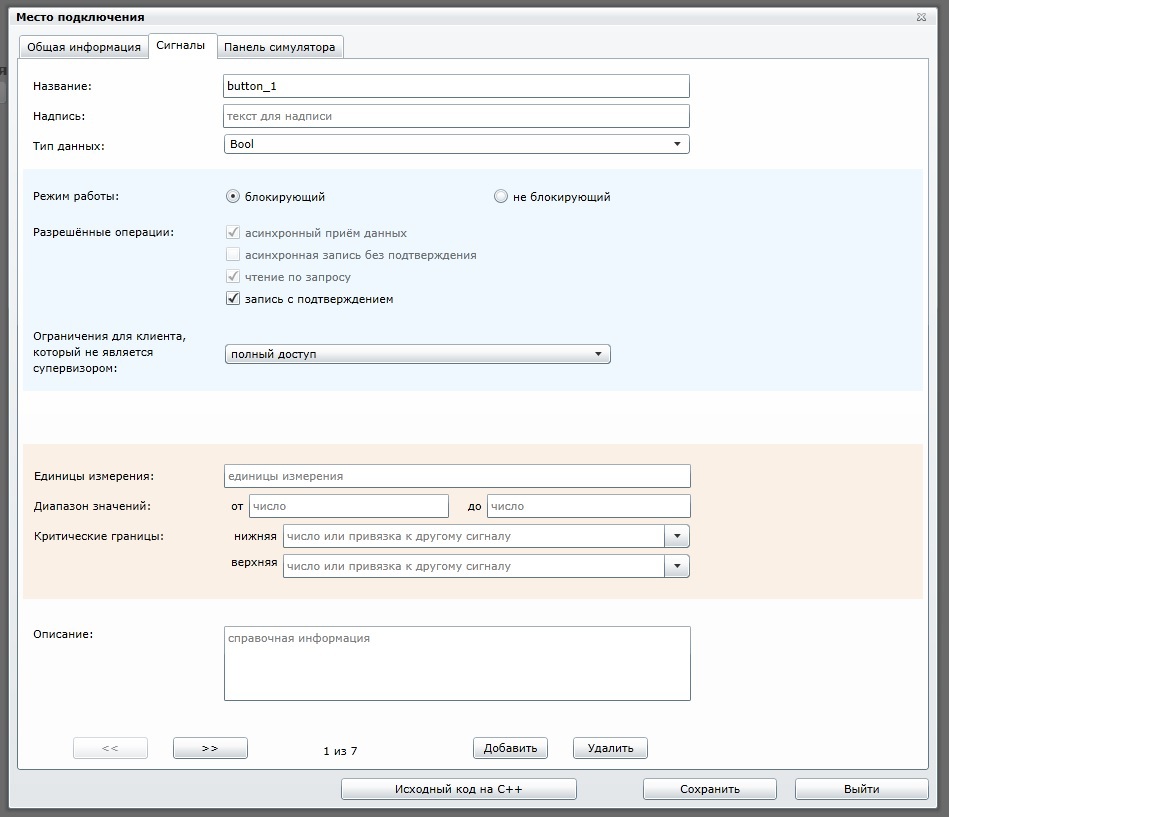
Before creating a control panel for your piece of iron, you need to create a "Connection Location". Each “connection point” is unique and is used as a link between the control panels and the electronic device.
At first glance, this entity is unnecessary, because it was enough to assign each parameter a global unique identifier.
But I acted differently, the binding of parameters is done by name, which makes this process more visual (the name may consist of several words). Naturally, the uniqueness of the names must be respected within the same "connection point".
The parameters mentioned above are another entity that has the name “signal” (the word “signal” is less overloaded in meaning). Each signal has its own type, allowed operations and access level. The access level is used only in the case when the control panel is laid out in general access, and protection is needed for a particular action, for example, so that no one except the host can record a certain parameter.
One “connection point” can connect up to 255 signals (for a single physical device, this number should suffice). For me it was important that the transport protocol was compact. For example, the transfer of one 4-byte parameter and 8-byte timestamp, as well as its name, will be packaged into 8 bytes (4 + 8 + name = 8). Such a GSM modem arithmetic will only thank you.
In general, with these terms, straight trouble, and all strive to invent ideas without need.
Perhaps the creation of signals is the most unpleasant place, but do not rush to throw stones, there is a reason for this. Based on this information, the source code of the working program will be automatically created for the developer (for the Arduino, Windows and FreeBSD platforms). This code will initially be operational and can be loaded into Arduino. For the developer, all that remains is to fill the signal handlers with a useful code (for example, turn on the LED or send a new button state).
Having received ready source codes and laconic API in the form of functions, the developer does not need to understand the exchange protocols. And in general, with this approach, the probability of errors is many times reduced.
Everything, the physical device is ready and connected to the Internet. Now it remains to create a control panel.
We place the controls on the panel, bind them to the desired signals.
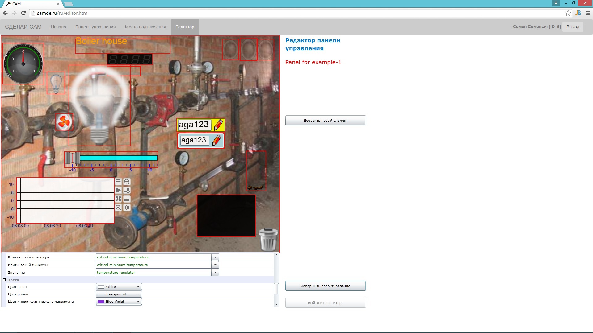
Now we’ll quit the editor and open the created control panel in the “My Panels” tab, then we will automatically connect to the equipment.
As a demonstration, I shared my Arduino, you can blink LEDs and take pictures from two JPEG cameras (as long as the household members didn’t wipe off the table).
What else would you like to implement:
1) Ability to embed custom SVG controls.
2) The mechanism of transition from cloud service to offline (when there is no Internet).
3) Data logging (not an easy task).
In any implementation there will be its pitfalls. I had a project where I developed a distributed system based on CANOpen, so there I laid a separate logic for working out emergency situations at each execution unit. There were about twenty nodes in the system. That was reliability, 100% testing of all abnormal situations, while the reaction of the entire system was within 5ms.
I was always wondering what solutions other developers are proposing in this area. Most often, that came across, these were quite serious tools with detailed documentation. However, it is difficult to expect something else from a full-fledged working tool.
In this regard, my service stands apart. And although it does not provide a comprehensive solution, it could be quite suitable for some tasks, because of its lightness. Ease of designing visual interfaces and a work program could speed prototyping devices. With the help of the mnemonic editor, you can quickly place controls, and then download the work program, modify it to fit your needs. Having been involved, all work can be done literally in five minutes.
The rapid creation of user interfaces, in our time, is not an exceptional feature; rather, it is a necessary minimum by modern standards. Another thing is the environment, that is, how much weight everything else will be, besides the interfaces themselves. A typical example is SCADA, but here the graphics will always be at its best, but does the developer want to test his piece of iron in battle to fasten it to the OPC server? Without a driver in advance, the developer will probably abandon the use of SCADA.
')
Where else to find a tool for creating interfaces? You can embed a Web server into the device, there are many ready-made visual elements for this, I don’t want to take it. I do not want? Is there no memory in the device for placing HTML pages? That is, some intermediate server (OPC server) is again asking for.
Therefore, a new direction of cloud servers has appeared, you send your data there, and they visualize your data through HTML pages. This trend is quite fresh, and at the same time, these solutions are already finding their customers.
For serious automation, this will usually not be acceptable, but in the household trifles, as cheap solutions, it is very well.
What I met among cloud solutions was aimed at storing user data. This is probably the most urgent task for which I do not yet have my own implementation. But, in my service, I did a good job of managing the issue in real time, developed compact protocols for data exchange, implemented authorization and stream encryption. All the same, management requires increased security, as opposed to monitoring.
Now about the implementation itself and some of the techniques that I used to create the service.
The service consists of a site directly, where the user can create his own account. Logging in to your account, the user will see a list of their own control panels. Each control panel can control one or several devices simultaneously.
The user also has a list of panels that friends have entrusted to him. And there is a third list of panels that are shared for everyone. You can entrust your panel to a friend or share it with all users of the service.
To design your panels, you need to go to the editor (for the editor you need the installed Silverlight plugin).
Sorry, sometime in the future, I will translate this editor to HTML5 technology and javascript (due to javascript I already believed and even managed to fall in love).
Before creating a control panel for your piece of iron, you need to create a "Connection Location". Each “connection point” is unique and is used as a link between the control panels and the electronic device.
At first glance, this entity is unnecessary, because it was enough to assign each parameter a global unique identifier.
But I acted differently, the binding of parameters is done by name, which makes this process more visual (the name may consist of several words). Naturally, the uniqueness of the names must be respected within the same "connection point".
The parameters mentioned above are another entity that has the name “signal” (the word “signal” is less overloaded in meaning). Each signal has its own type, allowed operations and access level. The access level is used only in the case when the control panel is laid out in general access, and protection is needed for a particular action, for example, so that no one except the host can record a certain parameter.
One “connection point” can connect up to 255 signals (for a single physical device, this number should suffice). For me it was important that the transport protocol was compact. For example, the transfer of one 4-byte parameter and 8-byte timestamp, as well as its name, will be packaged into 8 bytes (4 + 8 + name = 8). Such a GSM modem arithmetic will only thank you.
In general, with these terms, straight trouble, and all strive to invent ideas without need.
- Control Panel - a graphical interface for remote interaction with equipment;
- Connection point is a logical unit, connecting equipment and control panel;
- Signal - a certain parameter of the equipment;
- The editor is a tool for designing places and panels (Microsoft Silverlight plugin installation is required);
- Simulator - a graphical interface simulating the corresponding equipment.
Perhaps the creation of signals is the most unpleasant place, but do not rush to throw stones, there is a reason for this. Based on this information, the source code of the working program will be automatically created for the developer (for the Arduino, Windows and FreeBSD platforms). This code will initially be operational and can be loaded into Arduino. For the developer, all that remains is to fill the signal handlers with a useful code (for example, turn on the LED or send a new button state).
Having received ready source codes and laconic API in the form of functions, the developer does not need to understand the exchange protocols. And in general, with this approach, the probability of errors is many times reduced.
Everything, the physical device is ready and connected to the Internet. Now it remains to create a control panel.
We place the controls on the panel, bind them to the desired signals.
Now we’ll quit the editor and open the created control panel in the “My Panels” tab, then we will automatically connect to the equipment.
As a demonstration, I shared my Arduino, you can blink LEDs and take pictures from two JPEG cameras (as long as the household members didn’t wipe off the table).
What else would you like to implement:
1) Ability to embed custom SVG controls.
2) The mechanism of transition from cloud service to offline (when there is no Internet).
3) Data logging (not an easy task).
In any implementation there will be its pitfalls. I had a project where I developed a distributed system based on CANOpen, so there I laid a separate logic for working out emergency situations at each execution unit. There were about twenty nodes in the system. That was reliability, 100% testing of all abnormal situations, while the reaction of the entire system was within 5ms.
Source: https://habr.com/ru/post/251589/
All Articles