Another thermostat on Arduino, but with OpenTherm

Reading the first part of the heading, many of you probably thought - another thermostat on the long-suffering Arduino. And ... It's true - yes, this is another thermostat for the next boiler, the next house, but the truth is only partly - in the article I don’t want to concentrate on the device itself - there are really plenty of them (articles). Undoubtedly, I will describe the thermostat, but I would like to tell you more about how I connected the microcontroller with the boiler itself. So, who cares - please ...
How it all began
First of all, I want to say that I am not a programmer at all and have not dealt with this microcontroller before. My first acquaintance with AVR MK (and indeed with MK) was still in high school when I wanted to find out how this mysterious thing still works. I read several articles and since then I have only fragments left in my memory that could be described in just two words - DDR and PORT - and this was where my knowledge ended. Then there was the university, the 5th year - “Programming microcontrollers” where we all met MSC51 in a virtual environment. There were already interrupts, timers, and everything else. Well, with such a baggage of knowledge I came to the problem. Let's finish on this autobiographical note and move on to the more interesting part.
So, actually, how did the creation of the thermostat begin - after installing the autonomous heating with a gas boiler, I, like many, faced the usual problems - the temperature in the house was very dependent on the weather outside - frost - it was cold in the apartment, you need to increase the coolant temperature in battery powered, warmer - on the contrary. Such dances with a tambourine did not suit me much, because the adjustment of the boiler was complicated by the fact that it was installed behind the door, and the door was backed by a microwave, on which lay a pile of junk. Well, you understand - a needle in an egg, an egg in a duck, etc.
')
This problem was solved very simply - with an OTC sensor (Outside Temperature Compensation), which connects to the boiler and allows it to automatically adjust the temperature of the heat carrier depending on the outdoor temperature. The problem seemed to be solved, but reading the service manual on the boiler (Ferolli Domiproject C24D) quickly crushed my hope - the connection of the external temperature sensor in this model is not provided. Everything? Everything. So, probably, it would be possible to finish it, but in the summer, in a thunderstorm, the control board is still burning in an unintelligible way to me, and talking to the service man (the board was subsequently repaired), I asked if it was possible to connect the OTC to my boiler? He replied that they were connecting using external thermostats. This was deposited in my memory, but I didn’t really concentrate on it until the onset of cold weather, and then the exact same problem.
Leafing through the same service manual, but with the aim of seeing how the thermostat is connected, I noticed that the “OpenTherm controller” is connected to the same terminals. Here I understood - this is IT! Google search "OpenTherm Arduino" also disappointed me again - nothing particularly sensible. There was a message monitor, but this is not the case - I’m listening to, there’s nothing - the thermostat is needed.
Then I stumbled upon an article habrahabr.ru/post/214257 , the end of which upset me - the author without an oscilloscope could not connect the boiler with a microcontroller. And here, if a person’s acquaintance with MK didn’t work out, what should I try? A full description of the Opentherm v2.2 protocol was found on the Internet, which further cooled my heat - the physical level of the protocol was somewhat complicated - a current loop in which data from the boiler is transmitted by the current level (5-7mA - low, 17-23mA - high) , and from the thermostat to the boiler the voltage level (<7V - low level, 15-18V - high), which in turn will require a pairing circuit, and I am very close to electronics. Plus, the data was transmitted by the Manchester code, that ... well, you understand.
Only one conclusion - do not bother - just move the microwave and norms. But I have one peculiarity in character - if you put a certain idea in your head, then sooner or later it will come true - yes, I will forget about it (this idea), but still it’s not going anywhere (it turned out to be the case with home). media center on XBMC, satellite to it, on a DVB card, and many, many other things). You sleep, and the plan is already turning in your head, how to accept the Manchester code.
So, I will briefly describe how the OT / + protocol works (in the article above, OT types are described). Communication between devices takes place in a request-response format. The initiator can only be a thermostat. It sends a request at least 1 time per second and waits for a response from 20 to 800 ms. The messages themselves are 32-bit with one start and one stop bit:
Where MSG-TYPE is the message type for the thermostat:
0x0 - READ-DATA — read data;
0x1 - WRITE-DATA - write;
for the boiler:
0x4 - READ-ACK - confirm reading (it comes the answer);
0x5 - WRITE-ACK - confirm the record;
0x6 - DATA-INVALID - the data is incorrect;
0x7 - UNKNOWN-DATAID - there is no such DATA-ID.
DATA-ID - parameter identifier. The first 128 are reserved and most are already spelled out in the specification, the other 128 are each vendor using at their discretion.
DATA-VALUE - actually, the value of the parameter itself. It may be in a different format, depending on the parameter itself. Two 8-bit flag values, an unsigned 16-bit integer, a fixed-point fractional, etc. For each parameter, a value type is defined.
For each FROM device, a set of parameters is defined, which it must support without fail:
| Data id | Description | Thermostat | Boiler |
| 0 | Device Status Flags | Must send a read request, with the required functions set in the high byte of the DATA-VALUE field | Must respond to a request with status bits set in the low byte of the DATA-VALUE field |
| one | Setting the required temperature of the coolant | Must send a write request with the required temperature value | Must respond with confirmation that the required temperature is set. |
| 3 | Boiler configuration | Must read parameter | Must respond to the request and support all functions transferred in response |
| 14 | Maximum modulation level of the flame | Optional parameter | Must be implemented |
| 17 | Current flame modulation level | Optional parameter | Must be implemented |
| 25 | Coolant temperature | Optional parameter | Must be implemented |
The answer to all other parameters is at the request of the boiler manufacturer.
I will explain a little what flame modulation is for those who do not know. All modern gas boilers are able to regulate the level of flame in the firebox - this is called modulation. The greater the power of the burner, the faster the coolant heats up, too much power leads to constant on / off of the boiler (clocking), too low - to the inability to achieve the desired temperature. The best is the mode of operation in which the boiler does not turn off and burns with an intensity that is sufficient to maintain a given level of coolant.
As you can see - everything is extremely simple - write the implementation and get control of the boiler. But the devil, as they say, lies in the details. Remember the physical level - the data from the boiler is transmitted by the current level, to the boiler by the voltage level - a person new to electronics is confused. Food from the boiler? So how to control the voltage? You can not just connect the wires from the boiler to the Arduino. For those who know, the answer is obvious - this is the current loop and the interface circuit is quite simple. I’m somewhere in the middle, so I’m looking in the Internet and quickly found the otgw.tclcode.com site where enthusiasts made OpenTherm Gateway, however, on PIC. There was a pairing scheme. It would seem - take PIC, yes, please - a good attempt, laziness, but no - I want my own, not that.
That's all - take it, collect it. Then I began to ask the price for details and the set as a whole, but still there was an obstacle in the form of the Manchester code - I simply did not know which way to approach it in order to accept it. Here begins the next part of my story.
Manchester code
In the Opentherm protocol, the Manchester code is used for the physical presentation of data, or, as it is called in the Bi-Phase L specification.
Actually, here it is:
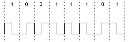
The whole point is that the bits are not encoded by the signal level, but by a transition between the levels in the middle of the period:

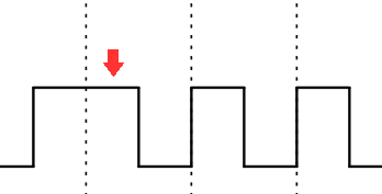
In addition, this very transition does not occur exactly in the middle of the period, but somewhere around:

As you can see, the period itself is 1ms -10% + 15% and the transition is somewhere in the middle.
This is where I stopped for a long time. There was no desire to copy something from the Internet, since each project has its own stumbling block, deciding which one feels not just a mindless copy-pasteur of libraries, but a developer who does this very project. This, in fact, is the heart of the thermostat - working with OT, copying it means simply collecting another toy from the designer, and not creating something of your own.
It was here that I wanted to apply all my poor knowledge of the MC - and interrupts and timers, etc. Yes, delay () is much simpler, but firstly the transmission is too slow to receive with delay (), but I wanted to perform other actions in parallel during the reception / transmission, secondly I wanted everything looked decent, and not as an odd student.
I thought I thought how beautifully to catch that transition, and even if it was a front or a decline, and when I looked at it from a different angle, everything became crystal clear why there was a transition at all! After all, the level of the first half of the period is the desired value of the bit:

There is a first step - to take the level of the first half of the period (somewhere after 250 μs after the start) - that’s all the decoding. But here I was waited by the following disappointment - it is not always possible to catch the beginning of the period: if a combination of 01 or 10 is on, then nothing remarkable happens between the periods, because It is obvious that the level does not change - you need to look further. And here the second revelation - in the middle of the period there is ALWAYS a transition - they are coded with 0 and 1. So you can attach to it, and the value of the next bit will be in half the period! It was here that everything finally became clear.
Imagine that we have already taken part of the bits and are just in the middle of the first period:
All that needs to be done is to enable the interrupt by changing the signal at the input. As soon as this happens, it means that we are exactly in the middle of the period. Turn off the interrupt by changing the signal, reset the timer, and make the timer interrupt somewhere in the period (which is 750 µs for the OT), when the timer interrupt is triggered, record the input level, turn off the timer interrupt, which is the required bit and repeat all over again for all the remaining bits.
A special case is the first bit, because wait for his level is not ¾ and ¼ period.
Quickly interrupt handlers were thrown and the firmware was assembled, but how could we debug it without an oscilloscope and a signal generator? The knowledge from the university came to the aid - Proteus, in which you could step by step to see what was happening.
Found, installed, and then all the charms of the practice went - it turns out that the interrupt flags must be forcibly removed before interrupts are turned on, and if you load OCR2A / B before changing the timer mode from FastPWM to CTC, then "this cool slurry turned out" in the program, but as it turned out in the gland is still more fun). Well, and other little things that quickly decided. I remind you that at this stage I didn’t have iron yet, and I didn’t have specific requirements for the thermostat.
I quote a code fragment responsible for receiving the Manchester code:
inline void OpenTherm::receive(){ cli(); first=1;//receiving first bit buf=0;//clear buffer rx=1; data_ready=0; length=0; parity=0; PCICR|=bit(rx_pcie); //enabling Pin Change Interrupt for RX port *rx_pcmsk|=rx_bitmask; //enabling Pin Change Interrupt for RX pin of rx Port TCCR2A=bit(WGM21);//mode CTC TCCR2B=0; OCR2A=TICKS_PER_MS*0.75;//interrupt at 0.75ms TCNT2=TICKS_PER_MS*0.5;//preload 0.5ms TIMSK2=bit(OCIE2A);//interrupt on OC0A TIFR2=bit(OCF2A); sei(); bool OpenTherm::extIntHandler(){ *rx_pcmsk&=~rx_bitmask; //Disable PCINT for RX pin if (first) { first=0; } else{ TCNT2=0; } if (length > MSG_LENGTH){ data_ready=1; TCCR2B=0;//disable Timer2 TIMSK2=0; return 1; } else TCCR2B=bit(CS22); //start timer clk/64 return 0; }; void OpenTherm::timer2CompAHandler(){ uint32_t tmp_buf; tmp_buf=buf; tmp_buf=tmp_buf<<1; if (rx) { if (*rx_port & rx_bitmask) { //Reading RX value tmp_buf=tmp_buf | 1; if (length > 1 ) parity^=1; //Don't calculate parity for start bit } *rx_pcmsk|=rx_bitmask; //Re-enabling PCINT for RX pin TCCR2B=0; //stop Timer2 } length++; buf=tmp_buf; }; } The transfer, later, perfectly logically and practically fit into the same handlers.
Timer 2 works all in the same CTC mode with zeroing every millisecond. In the zeroing interrupt handler (OC2A in CTC mode), switch the output according to the next bit. Additionally, the OC2B interrupt is enabled, which triggers at exactly half the period (0.5 ms) and the inverting state of the output. That's the whole wisdom of the transfer.
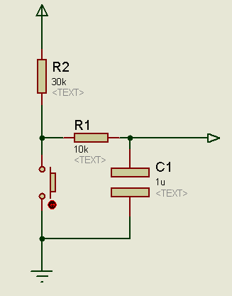
Here I collected the pairing scheme and in 3 hours I figured out the principle of its operation, which turned out to be quite simple, changed the scheme a little to transfer data in a direct, not inverted form, as in the original:

In addition, I had to write (well, how to write, take from the Internet and change for myself) the signal generator to HDL, because Manually type 34 bits in the Manchester code, this is not 4 or 5.
In the end, reception / transmission were established, and it was time to decide on the necessary equipment.
Equipment
So, I had a boiler (Ferolli Domiproject C24D) and the firmware for receiving / transmitting OT messages in the Manchester code in the emulator. It's time to move on.
What, above all, is necessary for almost every device on the Arduino? Arduino itself? Wrong! Enkoder, and certainly with a button, how is it different? It's just that I was always attracted to this type of input device - you have to try it.
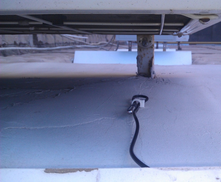
Next, the thermostat needs to get the temperature in the room and outside - for this purpose, 2 DS18B20 sensors will work, one will be filled with hot melt and put on the street, the second will be on the board. Naturally, a display is needed - without it, you can simply put radio components in a jar, wrap it in Silpo bag and prevent it - the effect is identical. I decided to take a standard sign-generating LCD 20 * 4 - it would have been enough, I2C port extender for LCD. The controller itself - quite enough Arduino Nano (now I would take the Pro Mini with a programmer, then I will tell you why). Well, a handful of details for the pairing scheme.
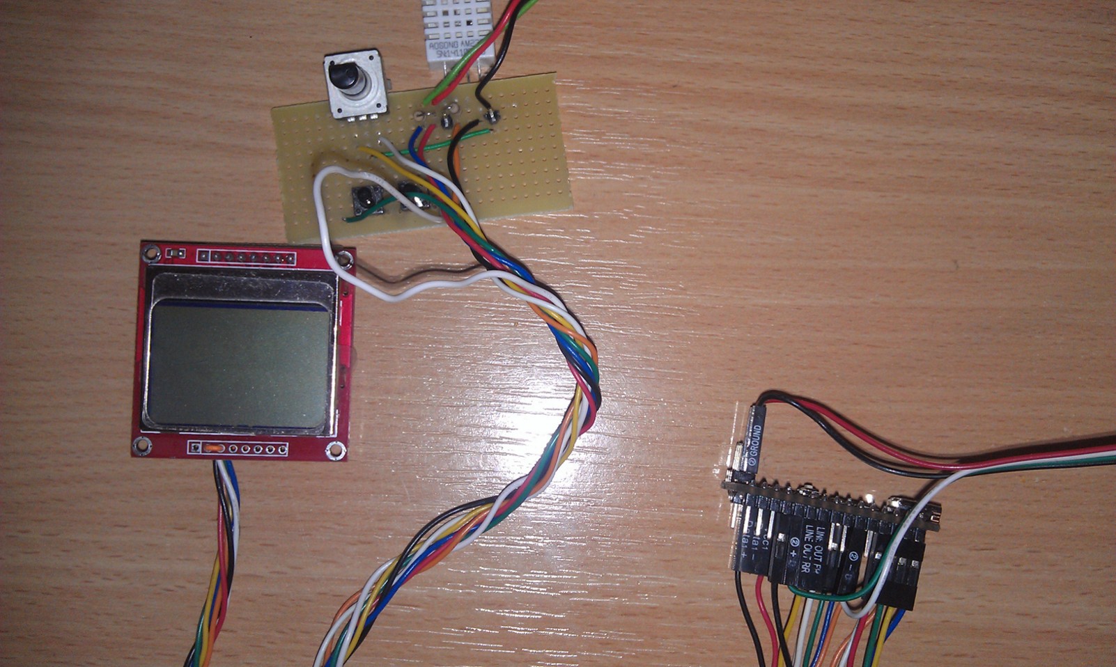
As you can see from the photo in the title, something went wrong. The seller had very attractive prices for everything, so I decided to change the list a little. Instead of two DS18B20, I took one in a waterproof case + DHT22, so now you can get more humidity in the room. LCD 20 * 4 was not available, and I took the display from Nokia 5110, there were no encoders with a button, so the usual + 2 buttons were taken.
After receiving everything was soldered and tested on test examples. The first thing we blink is the LED (as I understood when the Arduino board was first turned on, this is sacred). Everything worked as expected, so you can start to improve.
Despite the presence of hardware SPI on the Atmega 328, I decided to give it up, because the restrictions imposed by him did not make me very happy - MISO automatically adjusts to the input, and SS must be the output - minus two outputs, and therefore we leave the software SPI. I remove the CE display output control from the library and immediately connect it to the GND on the LCD. I get - something like:
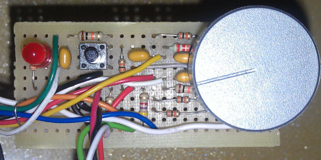
I expand the pairing scheme into Proteus and try to repeat something similar on the breadboard:

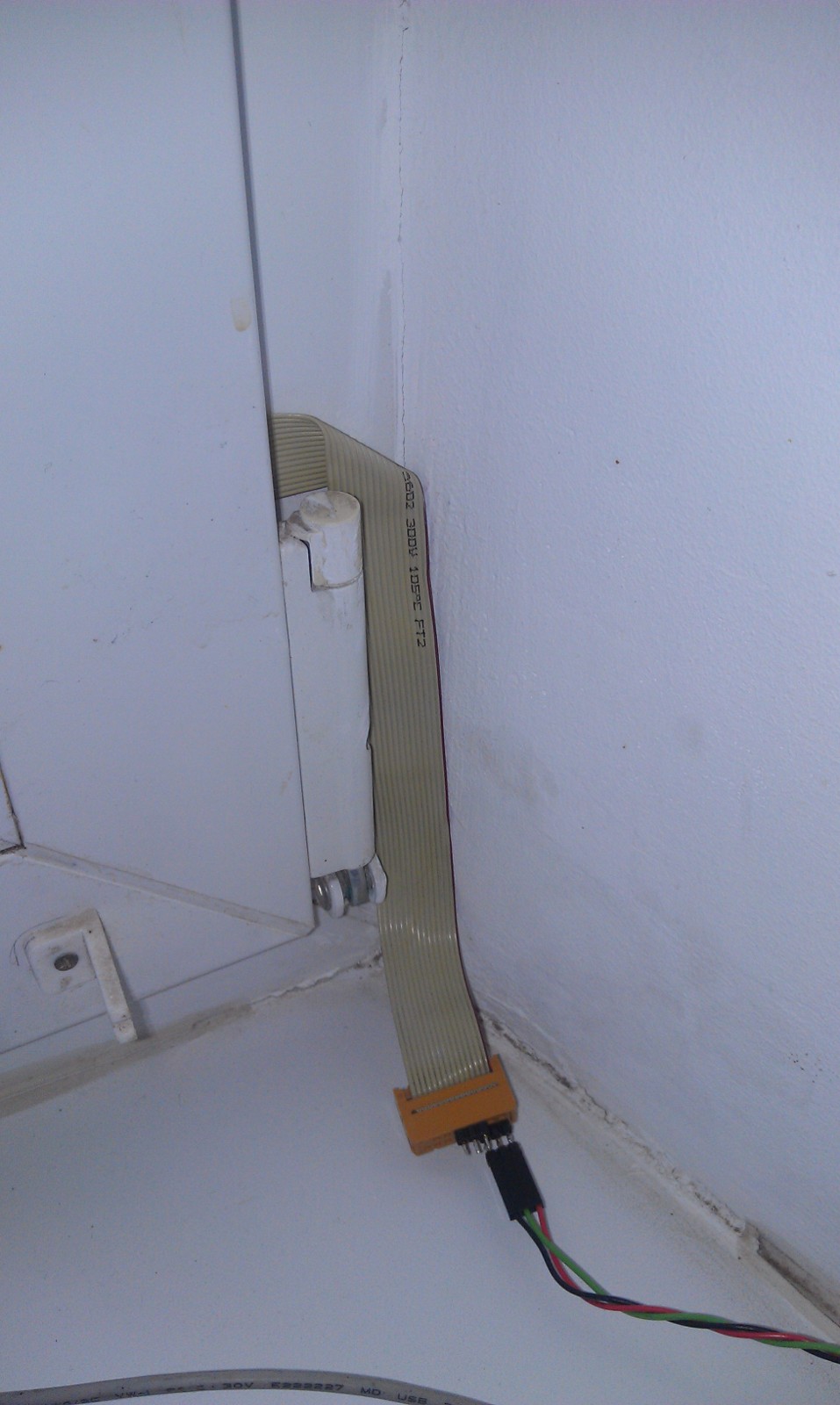
At the end of the wire you can see the standard terminal strip of the boiler, which turned out to be quite convenient - it is connected and disconnected without the use of tools and removing the cover.
Well, now you can write a primitive firmware and try to communicate with the boiler. I am writing, stitching, connecting, and ...
The boiler works as needed, the article can be closed.
Trollface.jpg
Naturally nothing works.
I poke the tester into the pairing board - it does not work - the input is always 20V. I make out, look, smile. I paid the payment from a friend. Immediately I remembered the dialogue.
-Well, a lot more?
No, almost done. Now this long path to solder and that's it. The main thing is not to forget to connect these two nearby contacts.
Guess from the first time that I forgot?
So the "Product" is fixed, I connect, I check. The levels are normal, you can connect the controller. Connect - silence. All - arrived. Further without an oscillograph there is nothing to do. I will finish as the author of the first article. But there is still a little hope.
We recall the part about receiving, and specifically resetting the timer on the level change in the middle of the period. I thought, you never know, suddenly zeroing is not enough and with the timings of the incoming signal is in general trouble, it means I will turn it off before that at the time of reading the level for a quarter of a period, and turn it on from zero to change - strangely, it helped. It was the same victory - without communicating with MK never before, write a library from scratch, which I did not find on the Internet, and even make it work the second time without an oscilloscope. My joy knew no bounds.
A little away from the feeling of euphoria, I realized that I needed to continue, because flashing the controller every time I needed to read a new parameter (the test firmware read the same parameter once a second), probably not much user-friendly.
I learned to get the values of the parameters, only in this form it is not a thermostat, but a remote display. In order for this to become what is required, you need to learn how to operate the boiler, and here surprises also awaited me.
Debugging and working with OpenTherm
So, the first value - the status of the boiler - received. The only thing that immediately embarrassed me - the DHW temperature when connecting the microcontroller immediately became the maximum allowable, regardless of the setting on the boiler panel, as I later read in the manual to the standard OT thermostat from the manufacturer (Ferolli Romeo W): when it is connected, the knobs serve only enable / disable the relevant functions, and no longer affect anything. It was logical to assume that the value of the DHW temperature parameter will remain as it was before connecting to OT, but Honeywell programmers (board manufacturer and the rest of the automation for the boiler) have their own opinion on this matter.
The control of the boiler was complicated by the fact that I didn’t have a sample thermostat on my hands to see the correct sequence of messages, so it was akin to being blindfolded. In the specification, the DHW Setpoint parameter was found (hereinafter, in parentheses, I will give the DATA-ID of the called parameters, in this case 56), which, apparently, was responsible for the DHW temperature. I rented, stitched - now when the button was pressed, the desired temperature was sent. Checking it is. The water temperature immediately became normal, it is time to start adjusting the CH Setpoint (1) - the temperature of the heating circuit - for which reason everything was started. Here I was stuck for a long time, for three days. No matter how hard I tried, whatever the desired temperature I set, the boiler still kept it around 30 degrees. I already had the idea that the manufacturer was protected from connecting other people's thermostats - the only obvious solution was to consider Member-ID (3) from the boiler and answer it the same (2). And this also did not help, briefly outlined the situation to a friend, and he had an assumption:
- Listen, what if one vendor for the master (thermostat) and slave (boiler) devices uses different Member-IDs. Count how the boiler automation is surprised when it realizes that another boiler controls it?
But everything turned out to be much simpler. It was in the parameter Max CH Setpoint (57) - the maximum temperature of the heating circuit. After the events with the DHW circuit, it was logical to assume that the maximum value is there, but no, the value was set at 30 degrees. After that, things went noticeably more fun.
Here begins the story of the thermostat.
Thermostat
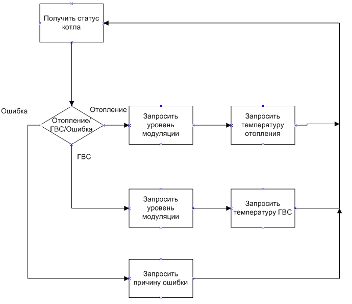
It is obvious that he should give out a bunch of boiler parameters, and be able to change them, without this there would be no point in creating another thermostat at all. As I said, each request must be sent approximately once a second, the most logical was to write a finite state machine that will go from one state to another once per cycle, and its states will respond to the current requested parameters. In the end, the branches of the machine turned out 3:
1. A working branch in which the current state of the boiler is polled, temperature, modulation level. In short, it can be represented as follows:
2. The branch of receiving information and the boiler: additional temperature sensors, flow sensors, etc. When you exit the "Info" menu, we return to the first branch.
3. The statistics receiving branch: burner operation time, number of fan / pump starts, etc. When exiting is identical to p.2.
For all this work, the function call update (), without parameters. It is enough to call it approximately 1 time per second. It receives the result of the previous query and sends a new one based on it. To switch between branches, you need to call a function with a parameter that is equal to the first parameter of the desired branch. For example, update (0) goes to the main branch (0 - request status of the boiler), update (18) - the second branch, which begins with a request for parameter 18 (pressure request in the heating circuit), branch 3 - parameter 116 (number of burner starts).
There are also other argument values:
1 - record the new temperature of the heating circuit;
56 - record the new temperature of the DHW circuit, etc.
All possible arguments can be seen at the end of the update function.
So, all the required parameters are obtained, but it was not done without a fly in the ointment - remember, I wrote after the table - all other parameters as desired by the boiler manufacturer? So - half of them in my boiler are zero, half are not known at all. Only wrote in vain, although it may even be useful to someone.
The most routine and boring task, quite obviously, was writing the menu. As promised, I will not go into details about the thermostat itself, everything can be seen in the final firmware
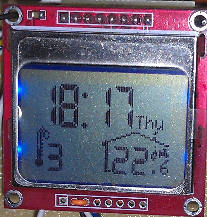
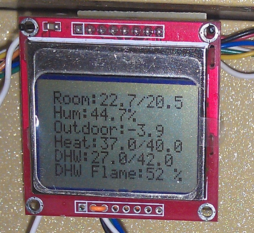
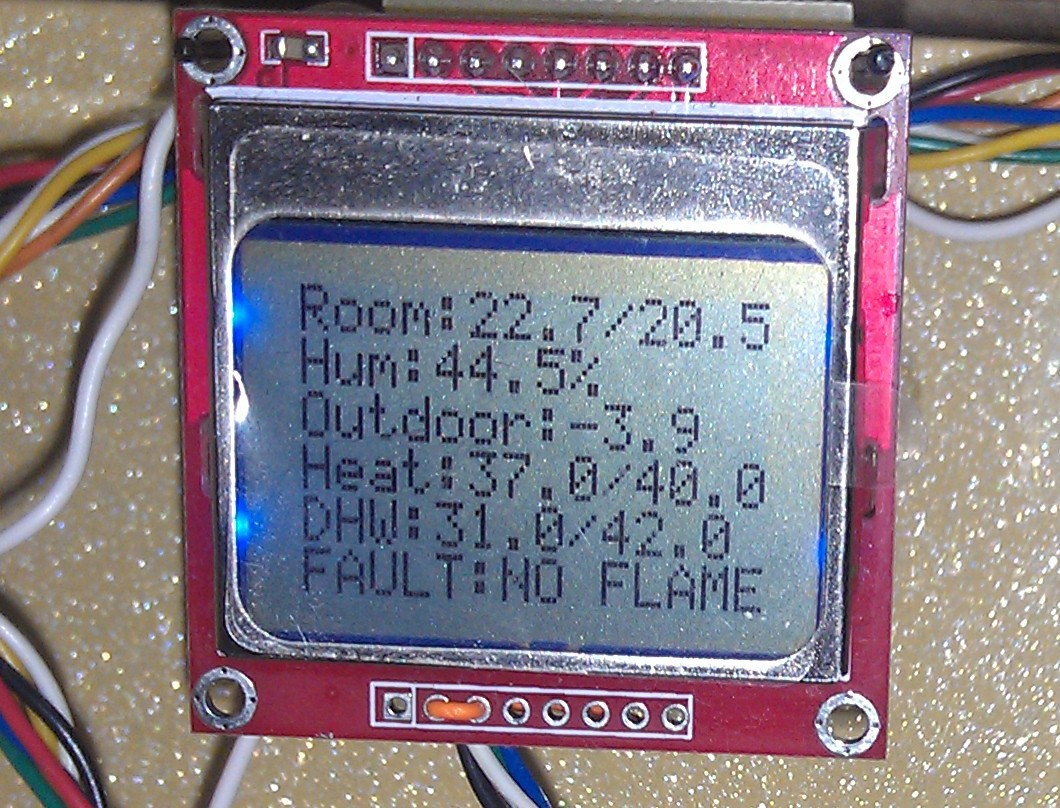
The last thing I decided to add at the time of writing this article is that instead of a boring screen with “many letters”, I made a semblance of a graphic display (something similar to a sample - factory Romeo W). Well, the clock - there are not many of them in the apartment, only the RTC DS323x is missing - when you turn off the power, you have to set the time again. To do this, I had to manually draw a few characters and add them to the font. The result can be seen in the photo in the title and below.
Sketch
#include <OpenTherm.h> #include <LCD5110_Basic.h> #include <OneWire.h> #include <dht.h> #include <dallastemp.h> #include <avr/eeprom.h> //#include <Power.h> #define DHT22_PIN 14 #define LCD_IDLE 0 #define LCD_MAIN 1 #define LCD_MENU 2 #define LCD_CONFIG_1 11 #define LCD_CONFIG_2 12 #define LCD_CONFIG_3 13 #define LCD_INFO_1 21 #define LCD_INFO_2 22 #define LCD_STATISTICS_1 31 #define LCD_STATISTICS_2 32 #define LCD_ITEM_MODE 1 #define LCD_ITEM_CH_EN 2 #define LCD_ITEM_DHW_EN 3 #define LCD_ITEM_CH_MAX 4 #define LCD_ITEM_CH 5 #define LCD_ITEM_DHW 6 #define LCD_ITEM_ROOM 7 #define LCD_ITEM_BRIGH 8 #define LCD_ITEM_ACTIVE 9 #define LCD_ITEM_MAX_MODULATION 10 #define LCD_ITEM_DAYS 11 #define LCD_ITEM_HOURS 12 #define LCD_ITEM_MINUTES 13 #define LCD_ITEM_KP 14 #define LCD_ITEM_KI 15 dht internal_s; OneWire ow(A1); Dallastemp external_s(&ow); OpenTherm ot(8,7); LCD5110 lcd(13,11,10,12,0); //Power sleep; extern uint8_t SmallFont[]; extern uint8_t MediumNumbers[]; extern uint8_t BigNumbers[]; //Encoder handling volatile uint32_t ts_enc=0; volatile int8_t encoder=0; //Clock handling uint32_t clock_ts=0,clock_delta=0; uint8_t hour=0,minute=0,second=0,day=0; //Menu Handling uint8_t menu,item; int8_t pos=0; const char* day_names[7]={"Mon","Tue","Wed","Thu","Fri","Sat","Sun"}; const char* mode_names[2]={"Manual","Auto"}; //Misc uint8_t display_enabled,cfg_enabled,button1=0,button2=0,item_tmp=0,update_period=0; float iSum; struct thermostat_config{ uint8_t address[8]; ot_init_settings ot_settings; float indoor_target_temp; uint8_t active_time; uint8_t brightness; uint8_t mode; uint8_t Kp; uint8_t Ki; uint8_t reserved[8]; }; //thermostat_config settings={{0x28,0xFF,0x53,0x76,0x60,0x14,0x02,0xFC},{1,1,70,30.0,40},22.0,30,130,1}; thermostat_config settings; /* ISR(INT0_vect){ ot.extIntHandler(); } */ ISR(PCINT0_vect){ ot.extIntHandler(); } ISR(PCINT1_vect){ ot.extIntHandler(); } ISR(PCINT2_vect){ ot.extIntHandler(); } ISR(TIMER2_COMPA_vect){ ot.timer2CompAHandler(); } ISR(TIMER2_COMPB_vect){ ot.timer2CompBHandler(); } ISR(WDT_vect) { // sleep.watchdogEvent(); } ISR(INT1_vect){ display_enabled=settings.active_time; OCR1A=settings.brightness; if((millis()-ts_enc >20) && cfg_enabled) { ts_enc=millis(); if ((PIND&bit(4))) { encoder++; } else { encoder--; } } } void fade_display(){ for(uint8_t i=settings.brightness;i>10;i-=10){ OCR1A=i; delay(20); } OCR1A=0; } void enc_setup(){ cli(); DDRD&=~(bit(3)|bit(4)); //set A and B to input EIMSK|=bit(INT1); EICRA|=bit(ISC11); EICRA&=~bit(ISC10); EIFR|=bit(INTF1); sei(); } void button_setup(){ DDRC&=~(bit(2)|bit(3)); } void read_config(){ eeprom_read_block(&settings, 0, sizeof(thermostat_config)); } void write_config(){ eeprom_write_block(&settings, 0, sizeof(thermostat_config)); } void lcd_idle(){ char mod_lev[2]={'\0','\0'}; lcd.setFont(BigNumbers); lcd.print(":",24,0); lcd.print(";",0,24);//";" - thermometer icon lcd.print("0",0,0); lcd.print("0",34,0); lcd.print("<=>",42,24);//"<=>" - House icon lcd.printNumI(hour,(hour>9)?0:14,0); lcd.printNumI(minute,(minute>9)?34:48,0); lcd.setFont(SmallFont); lcd.print(day_names[day],62,16); lcd.printNumF(internal_s.temperature,1,60,40); switch(ot.status&0x7){ case OT_STATUS_CH: lcd.print(">",78,32); break; case OT_STATUS_DHW: lcd.print("=",78,32); break; case OT_STATUS_FAULT: lcd.print("?@",72,32); break; }; if (ot.status&0x8){ if (ot.modulation < 34) *mod_lev='^'; else if (ot.modulation < 67) *mod_lev='_'; else *mod_lev='`'; lcd.print(mod_lev,72,32); } lcd.setFont(MediumNumbers); lcd.printNumF(external_s.getTemp(settings.address),0,6,32); lcd.printNumI(internal_s.temperature,48,32); } void lcd_main(){ lcd.print("Room: /",LEFT,0); lcd.printNumF(internal_s.temperature,1,30,0); if (settings.mode) lcd.printNumF(settings.indoor_target_temp,1,60,0); else lcd.print(" ",54,0); lcd.print("Hum: \%",LEFT,8); lcd.printNumF(internal_s.humidity,1,24,8); lcd.print("Outdoor:",LEFT,16); lcd.printNumF(external_s.getTemp(settings.address),1,48,16); lcd.print("Heat: /",LEFT,24); lcd.printNumF(ot.CH,1,30,24); lcd.printNumF(settings.ot_settings.CH_temp,1,60,24); lcd.print("DHW: /",LEFT,32); lcd.printNumF(ot.DHW,1,24,32); lcd.printNumF(ot.target_DHW,1,54,32); switch(ot.status&0x7){ case OT_STATUS_CH: lcd.print("CH ",LEFT,40); break; case OT_STATUS_DHW: lcd.print("DHW ",LEFT,40); break; case OT_STATUS_FAULT: lcd.print("FAULT:",LEFT,40); switch(ot.fault&0x3D){ case OT_FAULT_SERVICE: lcd.print("FAULT:SERV REQ",LEFT,40); break; case OT_FAULT_LOW_WATER: lcd.print("FAULT:NO WATER",LEFT,40); break; case OT_FAULT_GAS: lcd.print("FAULT:NO FLAME",LEFT,40); break; case OT_FAULT_AIR_PRESSURE: lcd.print("FAULT:AIR PRES",LEFT,40); break; case OT_FAULT_WATER_OV_TEMP: lcd.print("FAULT:WATER OT",LEFT,40); break; } break; default: lcd.print(" ",LEFT,40); break; }; if (ot.status&0x8) { lcd.print("Flame: %",24,40); lcd.printNumI(ot.modulation,60,40); } } void lcd_menu(){ lcd.print(" 1)Config",LEFT,0); lcd.print(" 2)Info",LEFT,8); lcd.print(" 3)Stats",LEFT,16); } void lcd_config_1(){ lcd.print(" Mode:",LEFT,0); lcd.print(mode_names[(item==LCD_ITEM_MODE)?item_tmp:settings.mode],RIGHT,0); lcd.print(" CH enabled:",LEFT,8); lcd.printNumI((item==LCD_ITEM_CH_EN)?item_tmp:ot.CH_enabled,RIGHT,8); lcd.print(" DHW enabled:",LEFT,16); lcd.printNumI((item==LCD_ITEM_DHW_EN)?item_tmp:ot.DHW_enabled,RIGHT,16); lcd.print(" CH max t:",LEFT,24); lcd.printNumI((item==LCD_ITEM_CH_MAX)?item_tmp:ot.CH_max,RIGHT,24); lcd.print(" CH temp:",LEFT,32); lcd.printNumI((item==LCD_ITEM_CH)?item_tmp:ot.target_CH,RIGHT,32); lcd.print(" DHW temp:",LEFT,40); lcd.printNumI((item==LCD_ITEM_DHW)?item_tmp:ot.target_DHW,RIGHT,40); } void lcd_config_2(){ lcd.print(" Room temp:",LEFT,0); lcd.printNumF((item==LCD_ITEM_ROOM)?(float)item_tmp/10+10:settings.indoor_target_temp,1,RIGHT,0); lcd.print(" Brightness:",LEFT,8); lcd.printNumI((item==LCD_ITEM_BRIGH)?item_tmp:settings.brightness,RIGHT,8); lcd.print(" Light time:",LEFT,16); lcd.printNumI((item==LCD_ITEM_ACTIVE)?item_tmp:settings.active_time,RIGHT,16); lcd.print(" Max modul:",LEFT,24); lcd.printNumI((item==LCD_ITEM_MAX_MODULATION)?item_tmp:settings.ot_settings.max_modulation,RIGHT,24); lcd.print(" Days:",LEFT,32); lcd.print(day_names[(item==LCD_ITEM_DAYS)?item_tmp:day],RIGHT,32); lcd.print(" Hours:",LEFT,40); lcd.printNumI((item==LCD_ITEM_HOURS)?item_tmp:hour,RIGHT,40); } void lcd_config_3(){ lcd.print(" Minutes",LEFT,0); lcd.printNumI((item==LCD_ITEM_MINUTES)?item_tmp:minute,RIGHT,0); lcd.print(" Kp",LEFT,8); lcd.printNumI((item==LCD_ITEM_KP)?item_tmp:settings.Kp,RIGHT,8); lcd.print(" Ki",LEFT,16); lcd.printNumI((item==LCD_ITEM_KI)?item_tmp:settings.Ki,RIGHT,16); } void lcd_info_1(){ lcd.print(" CH press:",LEFT,0); lcd.printNumF(ot.CH_water_pressure,1,RIGHT,0); lcd.print(" DHW flow:",LEFT,8); lcd.printNumF(ot.DHW_flow,1,RIGHT,8); lcd.print(" Ret.temp:",LEFT,16); lcd.printNumF(ot.CH_return_temp,1,RIGHT,16); lcd.print(" Max cap.:",LEFT,24); lcd.printNumI(ot.max_capacity,RIGHT,24); lcd.print(" Min mod.:",LEFT,32); lcd.printNumI(ot.min_modulation,RIGHT,32); lcd.print(" DHW min lim:",LEFT,40); lcd.printNumI(ot.DHW_min_lim,RIGHT,40); } void lcd_info_2(){ lcd.print(" DHW lim:",LEFT,0); lcd.printNumI(ot.DHW_max_lim,RIGHT,0); lcd.print(" CH lim:",LEFT,8); lcd.printNumI(ot.CH_min_lim,RIGHT,8); lcd.print(" CH lim:",LEFT,16); lcd.printNumI(ot.CH_max_lim,RIGHT,16); lcd.print(" Int.Sum.:",LEFT,24); lcd.printNumF(iSum,1,RIGHT,24); } void lcd_stats_1(){ lcd.print(" Burn.st:",LEFT,0); lcd.printNumI(ot.burner_starts,RIGHT,0); lcd.print(" CH pump:",LEFT,8); lcd.printNumI(ot.CH_pump_starts,RIGHT,8); lcd.print(" DHW p/v:",LEFT,16); lcd.printNumI(ot.DHW_pump_starts,RIGHT,16); lcd.print(" DHW bur:",LEFT,24); lcd.printNumI(ot.DHW_burner_starts,RIGHT,24); lcd.print(" B.hours:",LEFT,32); lcd.printNumI(ot.burner_op_hours,RIGHT,32); lcd.print(" CHpump H",LEFT,40); lcd.printNumI(ot.CH_pump_op_hours,RIGHT,40); } void lcd_stats_2(){ lcd.print(" DHWp/v H",LEFT,0); lcd.printNumI(ot.DHW_pump_op_hours,RIGHT,0); lcd.print(" DHWburn H",LEFT,8); lcd.printNumI(ot.DHW_burner_op_hours,RIGHT,8); } void update_clock(){ uint32_t tmp=millis()-clock_ts; clock_delta+=(tmp>0)?tmp:0; clock_ts=millis(); while (clock_delta >= 1000){ second++; clock_delta-=1000; if (second > 59){ second=0; minute++; if (minute > 59){ minute=0; hour++; if (hour > 23){ hour=0; day++; if (day>6) day=0; } } } } } void update_display(){ lcd.clrScr(); lcd.setFont(SmallFont); if (menu != LCD_MAIN && menu != LCD_IDLE) { if (pos>5){ pos=0; switch(menu){ case LCD_INFO_1: menu=LCD_INFO_2; break; case LCD_STATISTICS_1: menu=LCD_STATISTICS_2; break; case LCD_CONFIG_1: menu=LCD_CONFIG_2; break; case LCD_CONFIG_2: menu=LCD_CONFIG_3; break; default: pos=5; } } if (pos<0){ pos=5; switch(menu){ case LCD_INFO_2: menu=LCD_INFO_1; break; case LCD_STATISTICS_2: menu=LCD_STATISTICS_1; break; case LCD_CONFIG_2: menu=LCD_CONFIG_1; break; case LCD_CONFIG_3: menu=LCD_CONFIG_2; break; default: pos=0; } } }; switch(menu){ case LCD_IDLE: lcd_idle(); break; case LCD_MAIN: lcd_main(); break; case LCD_MENU: lcd_menu(); break; case LCD_CONFIG_1: lcd_config_1(); break; case LCD_CONFIG_2: lcd_config_2(); break; case LCD_CONFIG_3: lcd_config_3(); break; case LCD_INFO_1: lcd_info_1(); break; case LCD_INFO_2: lcd_info_2(); break; case LCD_STATISTICS_1: lcd_stats_1(); break; case LCD_STATISTICS_2: lcd_stats_2(); break; }; if (menu != LCD_IDLE && menu != LCD_MAIN) if(! item) lcd.print("\\",LEFT,pos*8); else lcd.print("*",LEFT,pos*8); } void setup(){ lcd.InitLCD(); lcd.setFont(SmallFont); lcd.clrScr(); enc_setup(); button_setup(); read_config(); //sleep.measure_wdt(1); // external_s.setRes(settings.address,TEMP_11_BIT); // external_s.startConv(settings.address); analogWrite(9,settings.brightness); display_enabled=settings.active_time; lcd.print("OT init.",CENTER,16); ot.begin(&settings.ot_settings); //sleep.measure_wdt(0); lcd.clrScr(); lcd.print("Slave OT ver.:",CENTER,0); lcd.printNumF(ot.slave_ver,1,CENTER,8); lcd.print("Slave Memb. ID:",CENTER,16); lcd.printNumI(ot.member_id,CENTER,24); lcd.print("Slave CFG:",CENTER,32); lcd.printNumI(ot.sl_cfg,CENTER,40); } void loop(){ //DEBUG //uint8_t type=0,id=0; //uint16_t data=0; float ext_temp,int_temp,t_error; if (!update_period) { internal_s.read22(DHT22_PIN); external_s.startConv(settings.address); } if(display_enabled){ OCR1A=settings.brightness; if(! --display_enabled) { fade_display(); cfg_enabled=0; menu=LCD_IDLE; item=0; delay(1000); ot.update(0); //main thread update_display(); } } if (cfg_enabled) delay (100); else delay(1000); //sleep 1s here // else sleep.sleep(); if (cfg_enabled || !update_period) { update_display(); } if ( (PINC&bit(2)) && button1) button1=0; //if button released reset state if ( (PINC&bit(3)) && button2) button2=0; //Esc if (! (PINC&bit(2)) && ! button1) { button1=1; display_enabled=settings.active_time; OCR1A=settings.brightness; cfg_enabled=1; switch(menu){ case LCD_IDLE: menu=LCD_MAIN; break; case LCD_MAIN: if ((ot.status&0x7) == OT_STATUS_FAULT) { delay(1000); ot.communicate(1,4,256); } break; case LCD_MENU: menu=LCD_MAIN; break; case LCD_CONFIG_1: case LCD_CONFIG_2: case LCD_CONFIG_3: if(! item) menu=LCD_MENU; else item=0; break; default: menu=LCD_MENU; break; }; pos=0; } //Enter if (! (PINC&bit(3)) && ! button2) { button2=1; display_enabled=settings.active_time; OCR1A=settings.brightness; cfg_enabled=1; if (! item){ //standart menu navigation switch(menu){ case LCD_IDLE: case LCD_MAIN: menu=LCD_MENU; break; case LCD_MENU: switch(pos){ case 0: menu=LCD_CONFIG_1; break; case 1: menu=LCD_INFO_1; delay(1000); ot.update(18); //start to get info break; case 2: menu=LCD_STATISTICS_1; delay(1000); ot.update(116); //start to get stats break; } break; case LCD_CONFIG_1: if (!item) item=pos+1; case LCD_CONFIG_2: if (!item) item=pos+7; case LCD_CONFIG_3: if (!item) item=pos+13; switch(item){ case LCD_ITEM_MODE: item_tmp=settings.mode; break; case LCD_ITEM_CH_EN: item_tmp=ot.CH_enabled; break; case LCD_ITEM_DHW_EN: item_tmp=ot.DHW_enabled; break; case LCD_ITEM_CH_MAX: item_tmp=ot.CH_max; break; case LCD_ITEM_CH: item_tmp=settings.ot_settings.CH_temp; break; case LCD_ITEM_DHW: item_tmp=ot.target_DHW; break; case LCD_ITEM_ROOM: item_tmp=(uint8_t)(settings.indoor_target_temp*10 - 100); break; case LCD_ITEM_BRIGH: item_tmp=settings.brightness; break; case LCD_ITEM_ACTIVE: item_tmp=settings.active_time; break; case LCD_ITEM_MAX_MODULATION: item_tmp=settings.ot_settings.max_modulation; break; case LCD_ITEM_DAYS: item_tmp=day; break; case LCD_ITEM_HOURS: item_tmp=hour; break; case LCD_ITEM_MINUTES: item_tmp=minute; break; case LCD_ITEM_KP: item_tmp=settings.Kp; break; case LCD_ITEM_KI: item_tmp=settings.Ki; break; } break; case LCD_INFO_1: break; case LCD_INFO_2: break; }; if (!item) pos=0; } else { //item save switch(item){ case LCD_ITEM_MODE: settings.mode=item_tmp; break; case LCD_ITEM_CH_EN: ot.CH_enabled=item_tmp; settings.ot_settings.CH_enabled=item_tmp; break; case LCD_ITEM_DHW_EN: ot.DHW_enabled=item_tmp; settings.ot_settings.DHW_enabled=item_tmp; break; case LCD_ITEM_CH_MAX: ot.CH_max=item_tmp; settings.ot_settings.CH_max_temp=item_tmp; delay(1000); ot.update(57); break; case LCD_ITEM_CH: settings.ot_settings.CH_temp=item_tmp; ot.target_CH=item_tmp; delay(1000); ot.update(1); break; case LCD_ITEM_DHW: ot.target_DHW=item_tmp; settings.ot_settings.DHW_temp=item_tmp; delay(1000); ot.update(56); break; case LCD_ITEM_ROOM: settings.indoor_target_temp=(float)item_tmp/10+10.0; break; case LCD_ITEM_BRIGH: settings.brightness=item_tmp; break; case LCD_ITEM_ACTIVE: settings.active_time=item_tmp; break; case LCD_ITEM_MAX_MODULATION: ot.max_modulation=item_tmp; settings.ot_settings.max_modulation=item_tmp; delay(1000); ot.update(14); break; case LCD_ITEM_DAYS: day=item_tmp; break; case LCD_ITEM_HOURS: hour=item_tmp; break; case LCD_ITEM_MINUTES: minute=item_tmp; break; case LCD_ITEM_KP: settings.Kp=item_tmp; break; case LCD_ITEM_KI: settings.Ki=item_tmp; break; } write_config(); item_tmp=0; item=0; } } /* ot.complete(&type,&id,&data); lcd.setFont(SmallFont); lcd.print(" / /",LEFT,40); lcd.printNumI(type,0,40); lcd.printNumI(id,12,40); lcd.printNumI(data,36,40); //debug */ if (encoder !=0 ) { if (menu != LCD_MAIN) if(!item) pos=constrain(pos+encoder,-1,6); else switch (item){ case LCD_ITEM_MODE: item_tmp=constrain(item_tmp+encoder,0,1); break; case LCD_ITEM_CH_EN: item_tmp=constrain(item_tmp+encoder,0,1); break; case LCD_ITEM_DHW_EN: item_tmp=constrain(item_tmp+encoder,0,1); break; case LCD_ITEM_CH_MAX: item_tmp=constrain(item_tmp+encoder,ot.CH_min_lim,ot.CH_max_lim); break; case LCD_ITEM_CH: item_tmp=constrain(item_tmp+encoder,ot.CH_min_lim,ot.CH_max_lim); break; case LCD_ITEM_DHW: item_tmp=constrain(item_tmp+encoder,ot.DHW_min_lim,ot.DHW_max_lim); break; case LCD_ITEM_ROOM: item_tmp=constrain(item_tmp+encoder,50,180); break; case LCD_ITEM_BRIGH: item_tmp=constrain(item_tmp+encoder*10,0,255); break; case LCD_ITEM_ACTIVE: item_tmp=constrain(item_tmp+encoder,10,100); break; case LCD_ITEM_MAX_MODULATION: item_tmp=constrain(item_tmp+encoder,10,100); break; case LCD_ITEM_DAYS: item_tmp=constrain(item_tmp+encoder,0,6); break; case LCD_ITEM_HOURS: item_tmp=constrain(item_tmp+encoder,0,23); break; case LCD_ITEM_MINUTES: item_tmp=constrain(item_tmp+encoder,0,59); break; case LCD_ITEM_KP: case LCD_ITEM_KI: item_tmp=constrain(item_tmp+encoder,0,255); break; item_tmp=constrain(item_tmp+encoder,0,255); break; } else if (settings.mode) settings.indoor_target_temp=constrain(settings.indoor_target_temp+encoder*0.1,15.0,28.0); else settings.ot_settings.CH_temp+=encoder*0.1; encoder=0; }; if (menu == LCD_IDLE && ! cfg_enabled && !update_period--) { update_period=60; update_clock(); int_temp=internal_s.temperature; ext_temp=external_s.getTemp(settings.address); t_error=settings.indoor_target_temp-int_temp; iSum=constrain(iSum+t_error,-ot.CH_max_lim,ot.CH_max_lim); if (settings.mode) settings.ot_settings.CH_temp=1*(20.0 + (settings.indoor_target_temp-ext_temp)) + settings.Kp*t_error + settings.Ki*iSum/256; if (settings.ot_settings.CH_temp < ot.CH_min_lim) ot.CH_enabled=0; else ot.CH_enabled = 1; settings.ot_settings.CH_temp=constrain(settings.ot_settings.CH_temp,ot.CH_min_lim,ot.CH_max_lim); if ((!settings.mode && ot.target_CH != settings.ot_settings.CH_temp ) || (settings.mode && abs(ot.target_CH - settings.ot_settings.CH_temp) > 0.5)){ ot.target_CH=settings.ot_settings.CH_temp; // delay(1000); ot.update(1); return; } } ot.update(); } -, , , . . , , , , -. -, .
:
1) CH Setpoint – ( / ).
2) OTC.
, ( (settings.indoor_target_temp-ext_temp)), .
OTC. , , , MIDI . (.. ). , .

, , , Power. . , delay(1000) , 1. , , Timer2 / OpenTherm , , . , Proteus Sleep, . , millis() ( watchdog-), . Pro Mini ( ) – + 3.3, . Power, , :
Power.h
#include <avr/wdt.h> #include <avr/sleep.h> #include <Arduino.h> class Power{ private: uint16_t wdt_delay; volatile uint32_t ts,delta; volatile uint8_t wdt_count; uint8_t calibration; public: void watchdogEvent(); void prepare_wdt(); void measure_wdt(uint8_t); void sleep(); }; Power.cpp
#include "Power.h" void Power::watchdogEvent(){ if (calibration) { delta+=millis()-ts; ts=millis(); }else wdt_disable(); wdt_count++; } void Power::prepare_wdt(){ wdt_reset(); WDTCSR|=1<<WDCE|1<<WDE; WDTCSR=1<<WDIE|1<<WDP2|1<<WDP1; } void Power::measure_wdt(uint8_t start){ cli(); if (start){ prepare_wdt(); ts=millis(); calibration=1; }else{ calibration=0; wdt_delay=delta/wdt_count; } sei(); } void Power::sleep(){ extern volatile unsigned long timer0_millis; prepare_wdt(); set_sleep_mode (SLEEP_MODE_PWR_DOWN); sleep_enable(); wdt_count=0; do sleep_cpu(); while(!wdt_count); timer0_millis+=wdt_delay; sleep_disable(); } , – , , :
– . , :
– , . , 3D-, , , . , :
— , ?
— ?
— , , , – .
:
A photo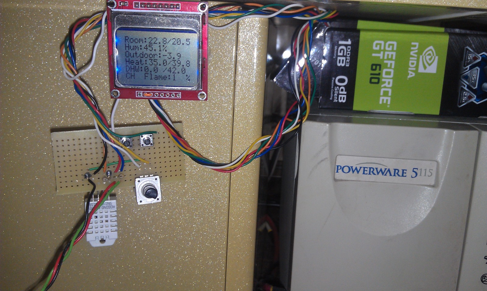
6x8: 0x98, 0x3c, 0x66, 0x99, 0x7e, 0x30, // 0x3c, 0x18, 0x1a, 0x1e, 0xba, 0xb0, // ( ) 0x04, 0xfd, 0x84, 0xfd, 0x84, 0xfd, // ( ) 0x00, 0xe0, 0x90, 0x8c, 0x82, 0xdd, // ( ) 0xdd, 0x82, 0x8c, 0x90, 0xe0, 0x00, // 0x00, 0x60, 0xf0, 0x7a, 0x20, 0x00, // 0x00, 0x70, 0xd8, 0x6d, 0x18, 0x00, // 0x0c, 0x72, 0xdb, 0x6c, 0x1b, 0x06, // 24x14: 0x00, 0xf8, 0x04, 0xfa, 0x85, 0x3a, 0x44, 0x44, 0x28, 0x00, 0x00, 0x00, 0x00, 0x00, 0x00, 0xff, 0xf0, 0xff, 0xAA, 0x00, 0x00, 0x00, 0x00, 0x00, 0x00, 0x00, 0x00, 0x00, 0x1c, 0x3f, 0x3f, 0x3f, 0x1c, 0x00, 0x00, 0x00, 0x00, 0x00, 0x00, 0x00, 0x00, 0x00, // 0x80, 0x80, 0xc0, 0xc0, 0x40, 0x40, 0x20, 0x20, 0x20, 0x10, 0x10, 0x10, 0x08, 0x08, 0x01, 0x01, 0xff, 0xff, 0x00, 0x00, 0x00, 0x00, 0x00, 0x00, 0x00, 0x00, 0x00, 0x00, 0x00, 0x00, 0x7f, 0x7f, 0x40, 0x40, 0x00, 0x00, 0x00, 0x00, 0x00, 0x00, 0x00, 0x00, // 0x08, 0x04, 0x04, 0x04, 0x02, 0x02, 0x02, 0x02, 0x02, 0x02, 0x04, 0x04, 0x04, 0x08, 0x00, 0x00, 0x00, 0x00, 0x00, 0x00, 0x00, 0x00, 0x00, 0x00, 0x00, 0x00, 0x00, 0x00, 0x00, 0x00, 0x00, 0x00, 0x00, 0x00, 0x00, 0x00, 0x00, 0x00, 0x00, 0x00, 0x00, 0x00, // 0x08, 0x08, 0x10, 0x10, 0x1a, 0x3b, 0x21, 0x20, 0x40, 0x40, 0x40, 0x80, 0x80, 0x80, 0x00, 0x00, 0x00, 0x00, 0x00, 0x00, 0x00, 0x00, 0x00, 0x00, 0x00, 0x00, 0x00, 0x00, 0x00, 0x00, 0x00, 0x00, 0x00, 0x00, 0x00, 0x00, 0x00, 0x00, 0x00, 0x00, 0x00, 0x00, // , , , update(), , communicate() — complete() —
Links
github.com/gavrilov-i/OpenTherm
habrahabr.ru/post/214257
otgw.tclcode.com
www.domoticaforum.eu/uploaded/Ard%20M/Opentherm%20Protocol%20v2-2.pdf
PS , , – — , . , .. , OpenTherm, .
PPS , . , — +5, TX ( ), RX ( ) — 1,5, GND.
:
— , . RX ( . ) TX ( R3) +5. 20. R3 — 7 ( 5). , . .
Source: https://habr.com/ru/post/251539/
All Articles