Implementation of the universal aquarium controller
In the following, I would like to demonstrate and share my work on the aquarium controller. In my opinion, the subject matter is very popular among aquarists, but not all aspects and problems have been considered. Maybe someone will be interested in something, or someone wants to repeat the design, so all the necessary files are attached to the topic. For those who want to delve into the software component of the device all the sources are attached.
At once I will make a reservation that everything was created for my own needs and the needs of aquarist friends. Everything described below is IMHO and does not pretend to "truth" or globalization of the solution to all existing problems.
Introductory part
The prerequisites for creating a controller are very commonplace - a 450-liter aquarium was purchased, and in addition there was a lid with installed lamps, electronic ballasts, coolers, a PH-electrode with an amplifier, and control of all this multi-channel controller. At first, everything worked without failures, but then the control triacs began to die, the current time was reset, and the functionality did not quite satisfy the increased requirements. After a long use and analysis of the existing controller, it was decided to make its governing body, and thought out the functionality of the future device:
')
1. Control 8 channels (+1 PWM channel):
- 4 channels of lighting;
- compressor;
- heater;
- electro-valve system CO2;
- pump / electrovalve avtodoliva;
- 12V cooler (PWM).
2. Connection of 3 temperature sensors DS18B20.
3. Connecting PH and Redox potential electrodes.
4. Connect the water level sensor (analog sensor).
5. As a switching element to use electromechanical relays.
6. Connecting a 4-line LCD on the HD44780 controller.
7. Availability of a real-time clock DS1307Z.
8. Communication with a PC can be organized in 2 ways:
- radio module using Bluetooth HC-05 (main channel);
- USB connection (backup channel).
9. Rated power switching load 650 watts.
10. The presence of electrical power supply filters and protective elements of the main circuits of the device.
11. Mark all connectors and connection pins.
PC software features:
- manual load control mode;
- 4 automatic modes (temperature mode, PH / CO2 mode, cover ventilation mode, automatic water pouring mode);
- use of 3 timers for each channel, with the possibility of setting the intervals by the second;
- calibration of electrodes;
- limiting the time intervals of the LCD backlight, the work of coolers and CO2 systems;
- data recording in non-volatile memory of the controller and various indication of the current system parameters.
With some amendments, this functionality can be classified as a universal device. This is certainly not entirely correct, because Aquarium controllers can be divided into 2 subgroups - for freshwater and marine life. In this case, the lighting regimes, the presence of various electrodes that determine the parameters of water, and the software modes that stabilize these parameters, etc., also differ. The hardware component of aquariums is also very different. Illumination can be arranged with fluorescent lamps, and LEDs or LED strips can be used. IMHO - the use of LEDs is a more attractive approach, both from the point of view of obtaining the necessary spectral composition, and in organizing control modes. However, the use of high-quality components, current stabilizers, power supplies and the issue of heat removal makes this approach more costly. Because of this, a large number of aquarists are still using fluorescent lighting, and are not going to change it yet. There can be a lot of differences, because ready-made solutions are rarely purchased, and most of the aquariums are tailored to the individual tastes of their owners. In this case, 3 aquariums were considered, and the requirements for them were combined / averaged. As a result, it turned out a system for a freshwater aquarium (or a herbalist), with fluorescent lighting, up to 500 l., An autonomous mode of operation, the output of the necessary information on the LCD and connecting to a PC for configuration.
Hardware implementation
Based on my personal experience, the experience of other developers, and the harmfulness of my IMHO, a sandwich design built on the basis of Arduino and others like him, I try not to use it. Never at all. The same applies to software (low or high level). Exceptions are external libraries, personally processed and passed more than one hundred hours of testing. Well, of course, standard libs, notepad, compiler, programmer / debugger and oscilloscope.
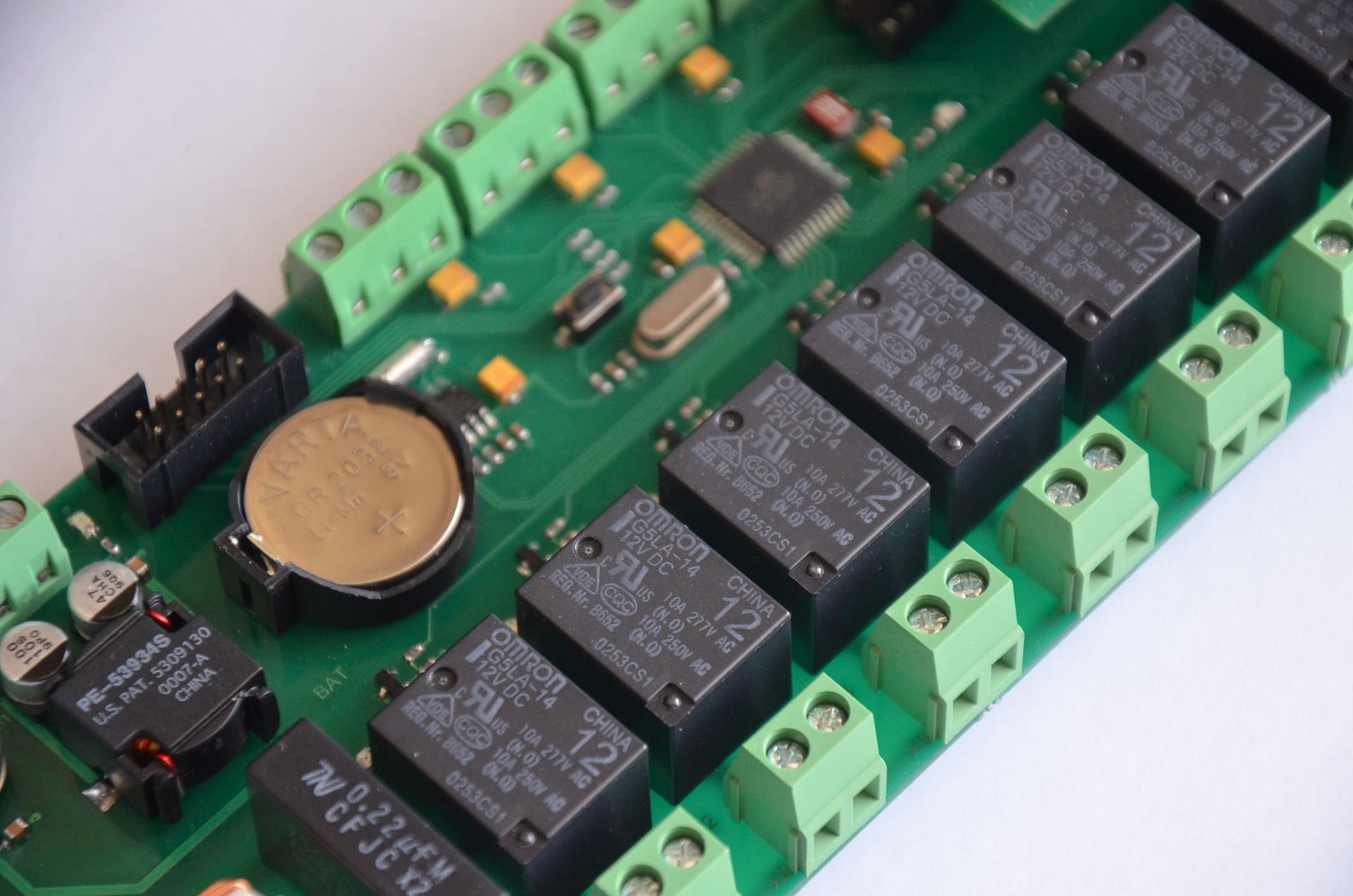
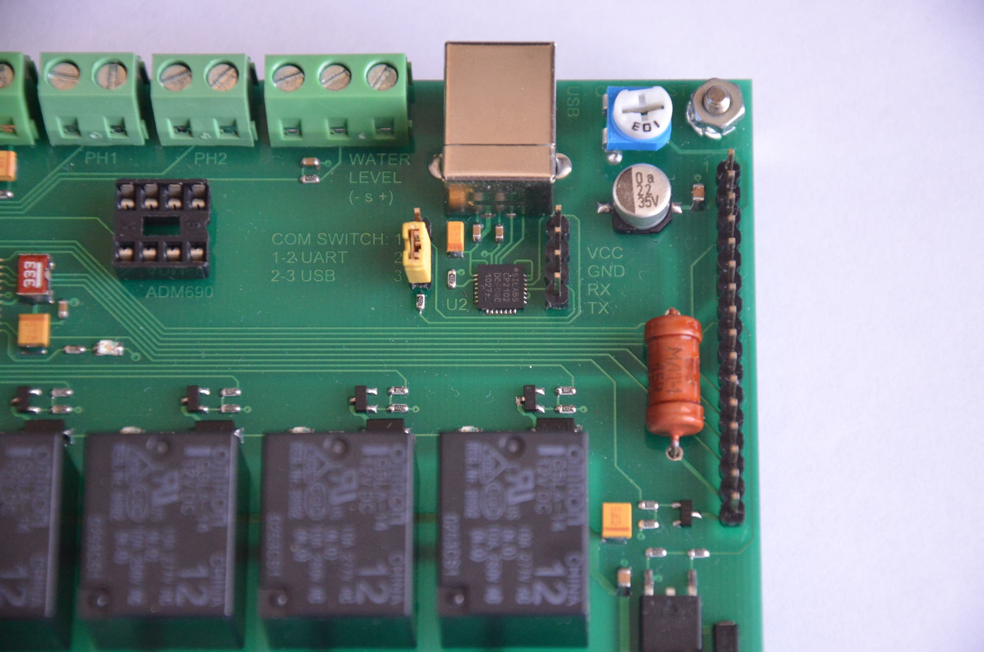
The hardware is based on the Atmel microcontroller - ATmega32A, operating from an external crystal oscillator of 11.0592 MHz. The choice is justified by the presence of a large number of flash and RAM, the necessary number of conclusions, so as not to feel cramped in the media (as a result, ~ 80% of the resources of the MC were used). The load switching is realized by means of an electromechanical relay. The device used sealed relay company OMRON, a series - G5LA. Receiving the current time is organized by the chip DS1307Z + precision thermostable resonator, previously taken from the Swiss industrial equipment. The choice was due to the presence of this chip and high-quality resonator. In another case, it is preferable to use DS3231. To control the coolers, a PWM signal is used. As a key element used field-effect transistor LR3714Z. A 4-bit bus is used to output data to the LCD, and the FMMT717TA transistor is used to switch the backlight. Communication with a PC is organized through a radio channel (RS232-Bluetooth HC05), or a RS232-USB converter CP2102. The data transfer rate is 9600 kbit / s. The mains voltage filtering is rated at ~ 650 watts nominal power. Termination of temperature sensors DS18B20 must be made in the immediate vicinity of the sensor. To improve the reliability of the device, an external supervisor ADM690ANZ was used, which monitors the clocking of the MK and the level of the supply voltage. The radio channel is implemented by a separate module that is connected to the controller board via a 4-pin connector. There is a variety of indications (channel activity, presence of supply voltages, MK clocking, data packet transmission).
I would like, of course, to use a Wi-Fi connection, with an HTTP server. But for this it is necessary to have an Ethernet MAC module available, which also draws on the need for a DMA interface - and this is not a task for the AVR. And the cost of an adequate Wi-Fi module is quite high. We will not consider a chain of several boards (I wrote about this in the beginning of the paragraph), or cheap Chinese modules capable of anything, but falling off every half hour. And from ARM7TDMI to a more recent architecture, I still can’t master myself. And it makes sense to use ARM for such a task, where the AVR is more than enough. Only for Ethernet / Wi-Fi - I see no point. In general, this is a task of another level. For the current standalone controller, it was decided to limit to USB / Bluetooth and an external supervisor.
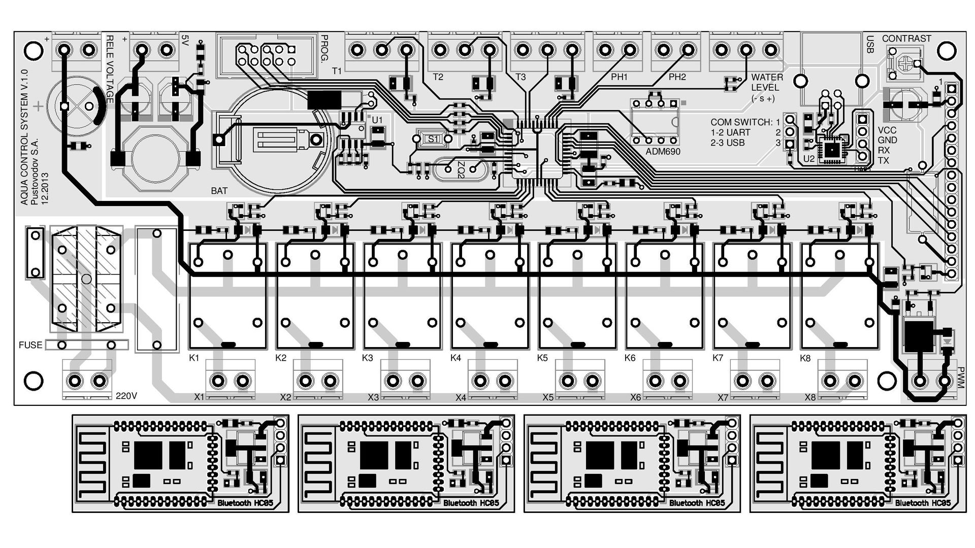
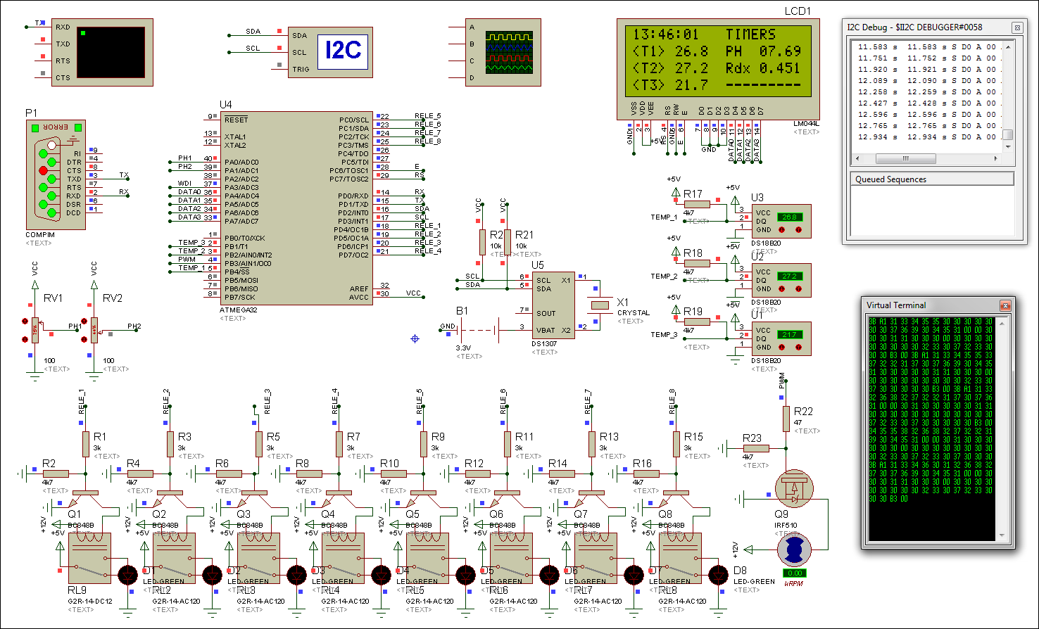
For the development of the device, the software product P-CAD 2006 SP2 was used. Below is a schematic diagram of the device (clickable):

The circuit board of the device was designed for SMD installation. Accuracy class is 4. Cases TQFP44, QFN28, SOT23, TAN-A, TAN-B, SMA, 0805, 0603, etc. are used. The board has a two-way implementation. General view of the printed circuit board of the device is shown below (clickable):
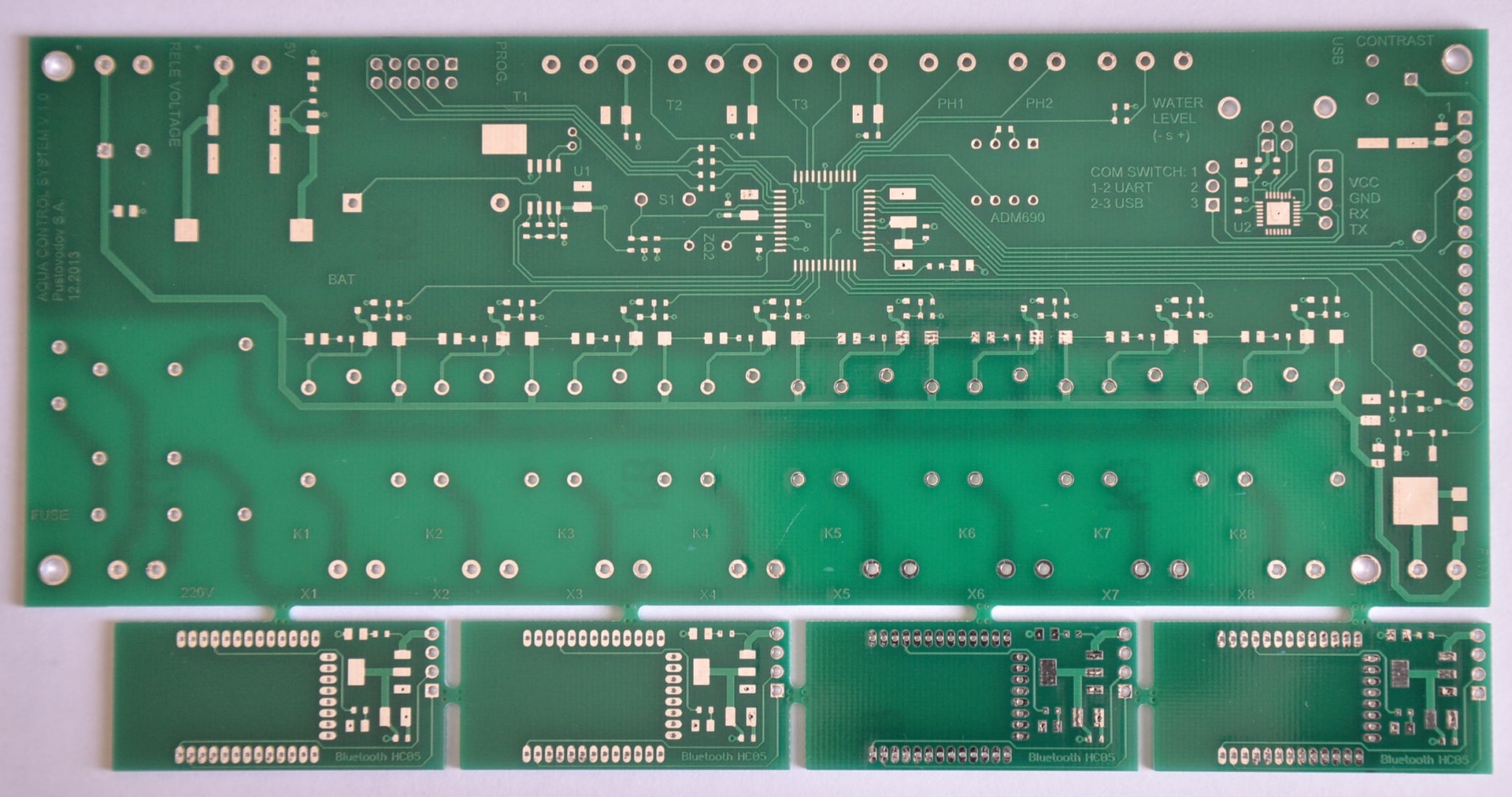
The manufacture of printed circuit boards was entrusted to Chinese specialists, because the quality of local manufacturers leaves much to be desired. Which company was engaged in the production of the board I can’t say, since I ordered it through a comrade, to whom I simply “fell on the tail” at the time of his order, and sent him all the necessary files. I was very impressed with the quality of the “heavenly”. The cost of one fee cost me about $ 20. It is also very pleased with the service provided. The cost of the board depended on its accuracy class, size, and other specified requirements. Within one working day, my order was processed, the exact date of arrival in my city was calculated and indicated. On the same day, the funds were already transferred to their account. And it was on that day that I received a message about the delivery of my package. Order processing, manufacturing and delivery took a little less than 2 weeks. None of the domestic manufacturers could offer me such a thing (at an adequate cost). Below is a photo of one of the boards received:
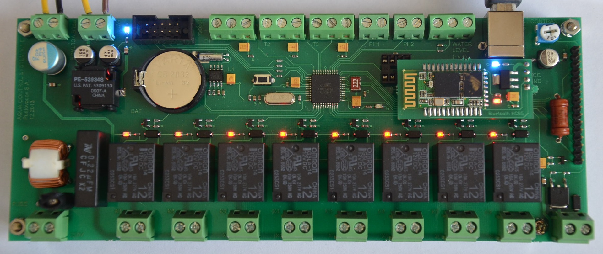
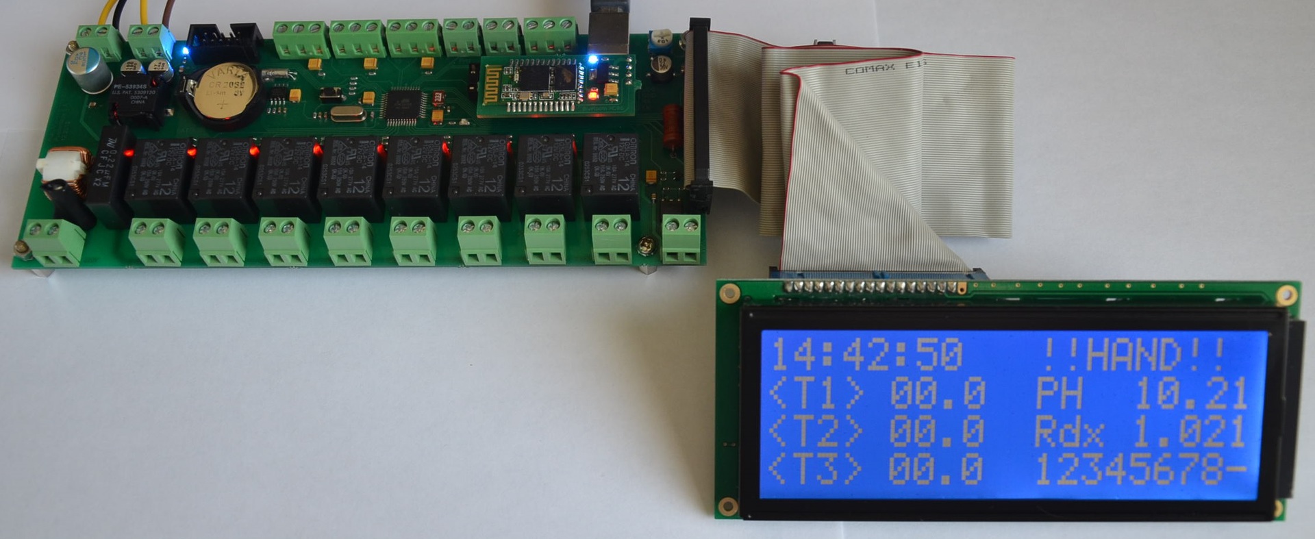
After soldering all the components, ultrasonic cleaning of the flux and controller firmware, the device acquired the following appearance:
To install the supervisor, an 8-pin socket is provided. The ADM690ANZ is very sensitive to fluctuations in the supply voltage, and if you do not have the opportunity to install a high-quality stabilized power supply to 5V, it is better not to use the supervisor. Otherwise, you will get more problems than the benefits of its use. To switch between USB and Bluetooth, use the appropriate jumper.
Initially, the device was planned to be installed in the cover of the aquarium. Therefore, the organization of the body is not provided. However, in the future, perhaps, the need for it will appear. To display the information, a 4-line LCD WH2004L-TMI-CTW, mounted on the front of the aluminum cover, was used. In order to avoid interference on the indicator, during the switching of the power load, the indicator itself must be isolated from the contacting metal parts of the cover, and the cable from the controller to the screen should be shielded.
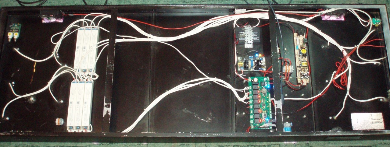
Well, at the end of the description of the hardware component below is a picture of the cover of the aquarium. It has the controller itself with a LCD, an uninterruptible power supply for 5V with a battery, a switching power supply for 12V, 6 electronic ballasts, an amplifier board for a PH electrode (based on CA3140E), 2 80mm coolers and a connector for network power with a simple input filter.
Implementing communication with the device
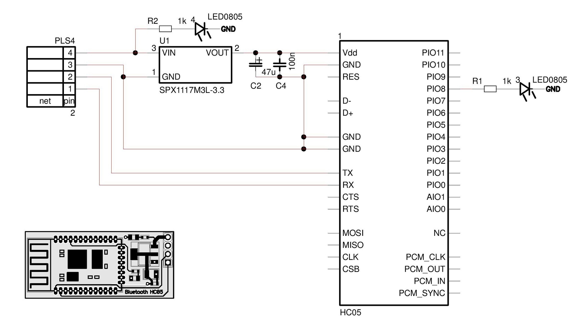
The main channel of communication is provided by the Bluetooth radio channel (HC-05), the USB connection is reserved. The device is not galvanically isolated between the microcontroller and the CP2102 level converter (USART-USB). When connecting via USB, you need to make sure that the power supply used for receiving + 5V and the power supply voltage of the PC are included in one electrical outlet (socket). Otherwise, incorrect operation of the device, the failure of certain structural elements. Below is a diagram and a printed circuit board of the radio module:
Software implementation
The software consists of 2 parts - low level (firmware) and high level (program for PC). For the development of the low-level part, the software product WinAVR was used, compiler version GCC 4.3.3. For the organization of control routines, a task manager based on a flag automaton was implemented. Several time intervals were allocated: 1 - 41ms, 2 - 167ms, 3 - 333ms, 4 - 1.34s, 5 - 2.67s, 6 - 10.6s. In the first time interval, the line-by-line display of information on the LCD is implemented. In the second - a survey of temperature sensors (~ once every 3 seconds), obtaining the current time, polling the ADC and calculating the values of the electrodes, taking into account the calibration coefficients. In the third time interval the main control functions of the controller are implemented:
- data processing of incoming packets;
- conversion of the current time into a numerical value (for convenience, all temporary values in the program are presented in numerical form HHMMSS);
- management of specified channels, in accordance with the selected modes of operation (once per second);
- PWM channel control;
- data processing control modes (temperature, PH / CO2 mode, cover ventilation mode, automatic water filling mode);
- setting time interval limitations (LCD backlight, operation of coolers and CO2 systems);
- write data to EEPROM;
- analysis of the current state of each of the channels, selected modes with a corresponding indication;
The fourth time interval is the formation of a clock signal for the supervisor. In the fifth interval - sending a packet of data on the current status of sensors, channel activity and control modes, and other information for display in a PC program. The last time interval is used to check the status of the water level sensor, when the auto-filling mode is on.
The project consists of several files: main.c, hd44780.h, i2c.h, USART.h, Functions.h, ds18b20.c, delay.h, crc8.c. Libraries for working with the 1-Wire bus were borrowed from an open project on one of the German sites and redesigned to fit their own needs (unused functions were removed and the indication of the port used and the MC output for the corresponding sensor were added). All the rest are written from scratch.
To debug low-level software, computer simulation of the device was used, using the Proteus 7.7 SP2 software package. The following is the assembled device diagram:
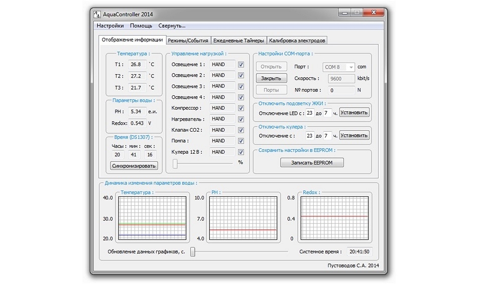
For the development of high-level software, Microsoft Visual Studio 2007 software was used. The main features of the software are represented by 4 tabs: information display, modes / events, daily timers, electrode calibration. Data is updated every 3 seconds. For data transfer the transaction method is used. The software sends the data packet to the device, which in turn, upon receipt, sends the received packet back to the PC. If the sent and received packets match, the transaction is successful. If the data is different, then the current data packet is sent again. If there is a multiple mismatch between the sent and received data packet, a connection error with the device is displayed. For data transmission, a string type was used, which makes it possible to accurately determine the beginning / end of the packet, its type, and the data itself. Below is the PC software interface:
A complete description of the operation of the AquaController 2014 software can be found in the help materials available through the Help / Help menu. A detailed description of the device is in the file "Technical Description".
The approximate cost of the device, including the delivery of components, ~ $ 100
This is the first implementation of the project aquarium controller. For more than six months, not a single failure in his work has been identified. Some design and software flaws are still there, but this is still not enough to develop the next prototype.
Given the operation of the current controller, a list of what can be further embodied in the following device:
- hardware implementation on ARM Cortex;
- Ethernet / Wi-Fi connection with the organization of the HTTP server;
- the presence of an external keyboard for emergency shutdown or activation of controlled channels;
- integration of the amplifier for PH and Redox electrodes on the controller board;
- the presence of controlled channels for LED backlighting;
- control of additional units (automatic feeder, fertilizer supply system, etc.);
- increased rated load power;
- replacement of DS1307 with DS3231;
- possibility of installation in one of the standard cases.
But for now, these are just plans for the future, as this controller fully meets the requirements of my current aquarium.
Below is the required documentation, software and source code of programs loaded on github: Aquacontroller 2014
Thanks for attention.
Source: https://habr.com/ru/post/251311/
All Articles