Adding Wi-Fi to various devices
Foreword
One of my good friend is engaged in building automation. And somehow over a beer, he complained to me about one of the objects that he had in use. The “head” of all the automation there is the PLC 100 of the well-known domestic manufacturer OWEN. It works autonomously, without outside intervention, but once a month it is necessary to remove logs from it and monitor the overall health of all automation in the building. The problem is that, for some reason, the Ethernet from the local grid was not carried out in the cabinet in which the PLC is located. To pull the wire, for some organizational reasons is not possible. And you can not hang a GSM modem, because the closet is in the basement where there is no network. At the same time, a local Wi-Fi network finishes the cabinet with the PLC, however, the PLC 100 does not have Wi-Fi.
And here it is necessary to travel every month to an object with a laptop, plug in a USB-RS232 adapter into the device and remove logs. As a result, I promised to “finish” the PLC by adding Wi-Fi to it.
General idea
Looking at the description of the device, I saw that on board it has Ethernet, two RS-232 and RS-485. At the same time, Ethernet, for the reasons described above, was useless for me. RS-485 was used as a fieldbus to control automation. But RS-232 was used only to remove logs. It was decided to modify it in Wi-Fi.
This required getting a UART-WIFI module, dismantling the PLC, finding the UART-RS232 chip and soldering directly to its UART (in other words, to the UART of the internal PLC processor on which the RS232 sits).
Having opened the PLC package, near the RS232 connectors, driver chips were quickly detected and identified. Interestingly, for two different RS232 ports, 2 different drivers are used: MAX3232 from Maxim and ADM3251E from Analog Devices.
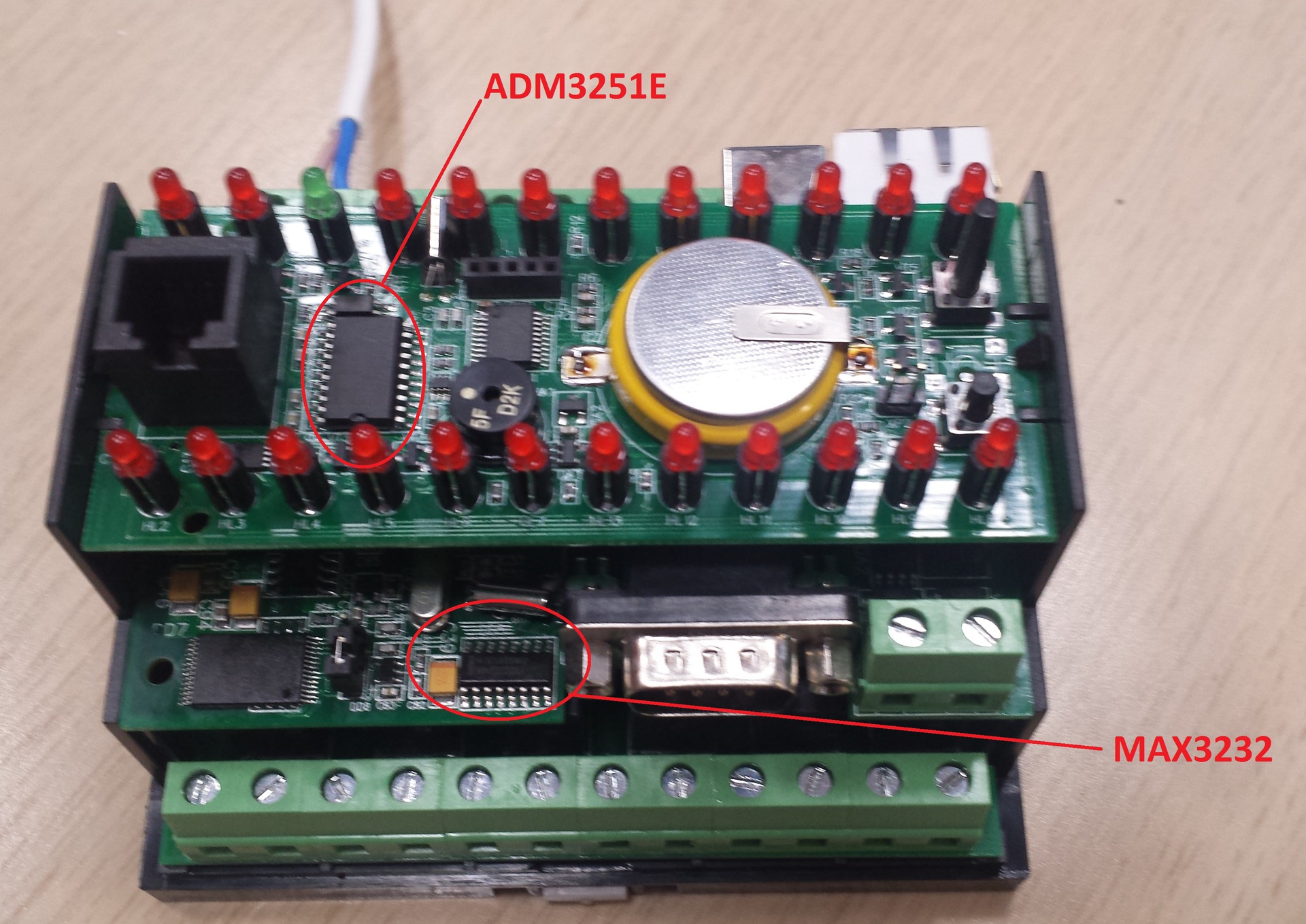
Well, for us it is not so important, because The driver will be removed from the board and replaced with a Wi-Fi module.
The second part is the search for a Wi-Fi module. The following requirements were set for him:
- output module mounting (ie, not SMD) - so that it is easy to solder to the terminals, and not iron the board under it
- availability of Transparent mode (UART-TCP bridge) - i.e. minimum number of AT commands required for operation
- the presence of the antenna directly on the module or the possibility of its easy connection
- Of course, UART control
- preferably, price up to $ 10
First of all, there was an idea to use a module based on the esp8266 chip rattling the entire runet. But after reading about it on the Internet, I didn’t understand whether it contains the Transparent mode and, besides, many hints that the firmware with the AT commands is not stable enough yet. In general, I decided to look for more.
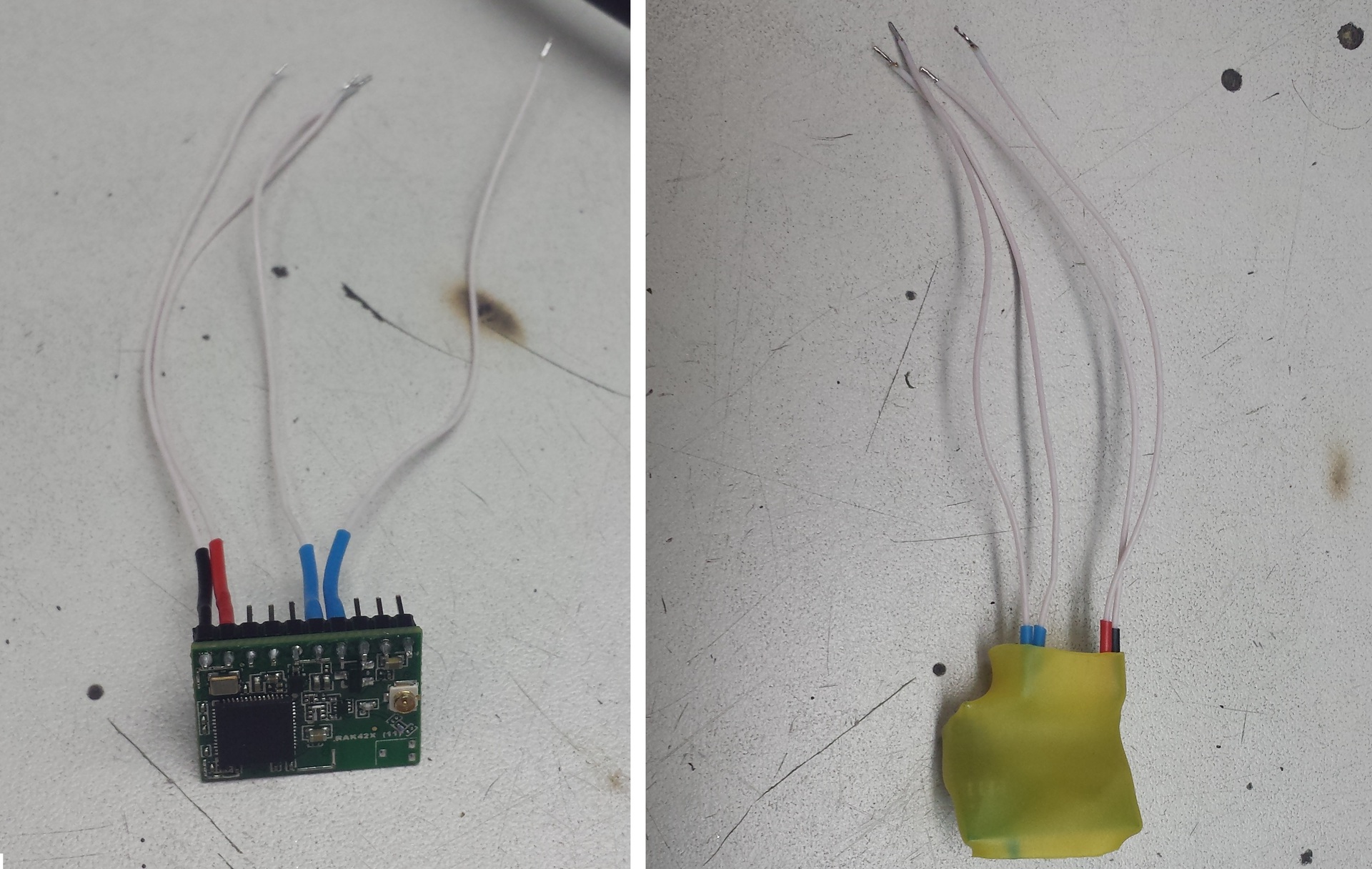
As a result, on aliexpress, a module named RAK425 was found to be very suitable for the description. The manufacturer of this miracle was easily fucked by the module name. The manufacturer’s website had imputed documentation and some other files that I didn’t see. The guys impressed me as "decent" Chinese, so it was decided to take. True, it was not possible to find a piece sale, so I bought a “package” of 5 stuff for $ 50, not counting the delivery - let it lie, I will find the use and the rest over time.
')
We work as a soldering iron
First of all, open the datasheet on the ADM3251E chip and look for contacts to power its TTL level - Vcc, GND (pins 2 and 10 respectively). Our Wi-Fi module is powered by 3.3V, so just in case you need to measure what is powered by ADM3251E in ARIES. Here is a bummer - a multimeter showed 4.9V.
Try happiness with MAX3232. According to the datasheet, the power goes to pins 15 and 16. I was lucky and the power supply there is 3.3V, so we decide to connect the module here.
And what if the power is not 3.3V?
If the power supply is more, then you can use an inexpensive and easily accessible linear voltage regulator a la krenka, in some output package of the type TO-92. Type LP2950CZ-3.3 / NOPB - apparently must pull on current.
We prepare the Wi-Fi module by soldering 4 wires to the necessary contacts (Vcc, GND, RxD and TxD according to the pinout from the documentation). The module itself can be put directly into the enclosure of the PLC100. In order that he there did not hesitate to wrap the module in heat shrinkage.
Now we find in the datasheet on the microcircuit contacts to which you need to solder the lines RxD and TxD. We take out the driver and put our module in its place:
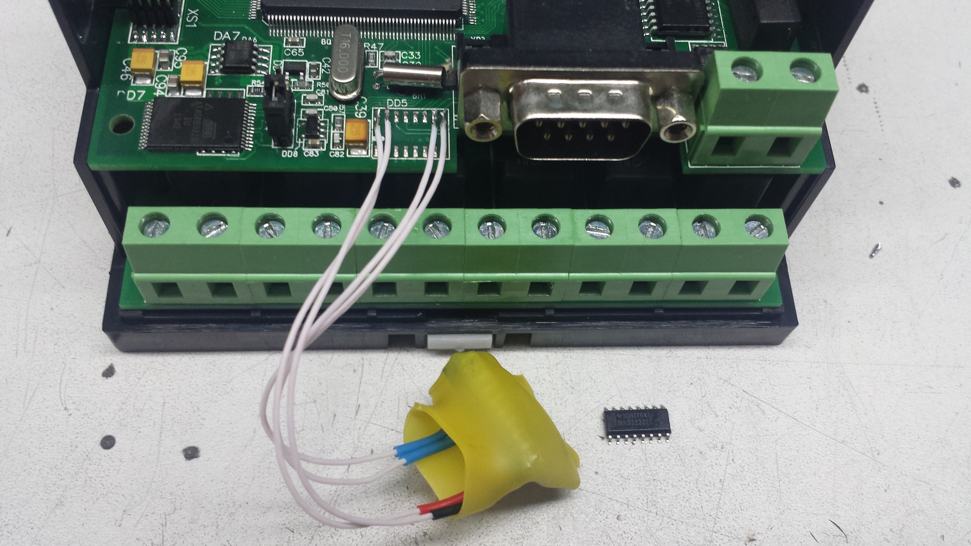
Now we put the module inside the PLC and assemble it. Everything fits very well, so the PLC looks outside pristine untouched.
Configuring W-Fi Module
What I liked about the RAK425 is that the transparent transmission is beautifully realized in it, i.e. the transparent UART-WIFI bridge in it is organized in general without the support of AT commands, i.e. for the program in the PLC100, the transfer process to the computer did not have to be changed at all - it still believes that it is transmitting data to RS232.
It works like this: after powering on the module raises its own access point. Having connected with the laptop to this point, we type in the browser the address of the module (by default 192.168.7.1) and get to its web page settings. There we write the name of the Wi-Fi network to which we want to connect and the password to it. As well as the TCP connection parameters: I opened a TCP server on the module on port 1234. We reboot the PLC100 on power (and therefore our module) and after the restart the module connects to our Wi-Fi network. Now all the data that we send to our server are automatically relayed to the UART module (and therefore to the UART of the PLC100 processor).
I don’t see any point in screenshots of the configuration process, everything is very simple, understandable and described in the documentation.
On this, in general, that's all. The only thing that was needed next was to forward the port to the IP of our module in the router at the facility and monitor the status of the automation over the Internet. Already the second month is running out, how everything works there and you don’t have to go to the site every month. Comrade laf, me a bottle of brandy.
Conclusion
The purpose of the article is not to show how to fasten W-Fi to a specific PLC100 (it is unlikely that someone else will have the same task), but to demonstrate one of the possible approaches for setting up remote access to any equipment that was not originally intended for this.
The way is easier and faster. But not so exciting.
After everything was done and started, I was told about a simpler way of implementing the same. As it turned out, many modern routers are able to work in reverse mode, i.e. Wi-Fi is used as WAN, and Ethernet is used as LAN. I just didn't know that then.
Potential disadvantages of such a decision:
Potential disadvantages of such a decision:
- it is necessary to feed the router with something - not the fact that there is such an opportunity in the closet;
- a DIN rail router is expensive and not a fact that it can do that. Not DIN-rail router can "not please the gaze" of local electricians
Source: https://habr.com/ru/post/251167/
All Articles