A short course in computer graphics, addendum: ambient occlusion
The official translation (with a bit of polishing) is available here.
In a brief course on computer graphics that I submitted to your review a couple of weeks ago, we used local lighting techniques. What does it mean? This means that we chose the intensity of illumination of each point independently of its neighbors.
Phong's lighting model is a classic example of local choice:
')
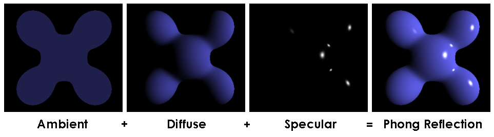
The final intensity consists of three components: ambient lighting, constant value for all points of the scene. Diffuse lighting and glare depend on the normal vector to a given point and the direction of light, but do not depend on the geometry of the rest of the scene. Let's think, why, in fact, was the ambient lighting chosen constant for the whole scene?
The second approach to global illumination: ambient occlusion
Well, actually, I was a little wrong when I said that in that course we had local lighting. In the sixth part, we considered the construction of the shadow cast by our object. And this is one of the techniques of global illumination. In this article, I propose to consider a few simple approaches to the calculation of ambient light. Here is an example of a model in which I used only the ambient component of the Phong model's lighting, no diffuse light, no glare.
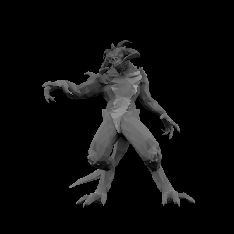
So, the task is set as follows: calculate the value of ambient lighting for each point of the visible part of our scene.
When Phong said that the environment around is so velvety and fluffy that reflects equally light in all directions, it was a somewhat powerful simplification. Of course, this was done in favor of local lighting methods, which are much faster than global ones. Recall that to build the shadow, we had to render in two passes. However, with modern iron, we can afford to be able to give a little more attention in order to get a more believable picture. In real life, if you see the entrance to the tunnel, then quite clearly it will be less illuminated by sunlight than the surrounding mountain.
Enough plausible images are obtained if we assume that our object is surrounded by a uniformly luminous hemisphere (for example, an overcast sky). But this does not mean that the tunnel also glows inside, which means that we will have to do additional work, calculating how each point of the object is visible from our luminous hemisphere.
We go to the forehead
Accompanying source code to take here .
The easiest way is to randomly select, say, a thousand different points on a hemisphere around an object, render the scene a thousand times with a camera set at these points, and calculate which parts of the model we saw. It is appropriate to ask a couple of questions.
Question 1: Do you know how to choose with a uniform distribution a thousand points on a sphere without accumulation around the poles?
Something like this:
Hidden text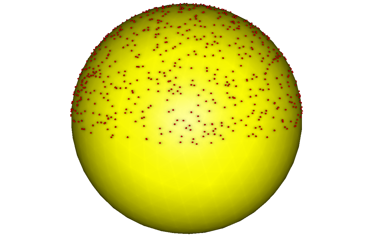
After all, if we simply randomly (uniformly) choose latitude and longitude, then at the pole we will have a wonderful clot, which means that our assumption that the light reflected by the world of light is not true. Examples of ready-made calculations can be found here .
Question 2: where to store information about which piece of the luminous hemisphere is visible from this point of the object? As we walk in the forehead, the answer is almost obvious: in the texture of the object!
So, we write two shaders and render two times for each point. Here is the first (fragmentary) shader and the result of its work:
virtual bool fragment(Vec3f gl_FragCoord, Vec3f bar, TGAColor &color) { color = TGAColor(255, 255, 255)*((gl_FragCoord.z+1.f)/2.f); return false; } Hidden text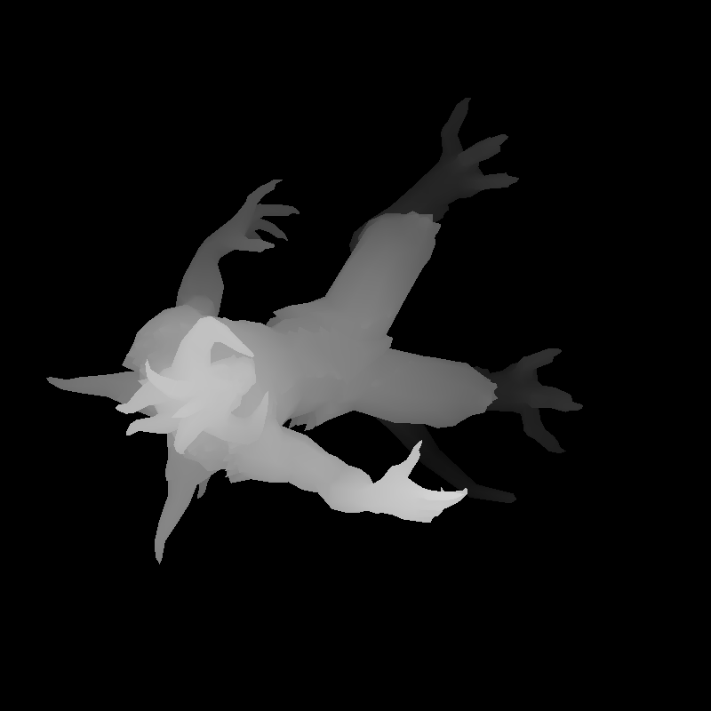
The picture itself doesn’t particularly interest us, we are interested in the z-buffer as a result of the operation of this shader.
Then we make the second pass with this fragmentary shader:
virtual bool fragment(Vec3f gl_FragCoord, Vec3f bar, TGAColor &color) { Vec2f uv = varying_uv*bar; if (std::abs(shadowbuffer[int(gl_FragCoord.x+gl_FragCoord.y*width)]-gl_FragCoord.z)<1e-2) { occl.set(uv.x*1024, uv.y*1024, TGAColor(255)); } color = TGAColor(255, 0, 0); return false; } It is absolutely not important for us that it will display a red picture. This line is interesting here:
occl.set(uv.x*1024, uv.y*1024, TGAColor(255)); occl is a 1024x1024 image that was initially filled with black. And this line says that if we see this fragment, then we will mark it in the occl texture map. This is what the occl picture looks like after the rendering is finished:
Hidden text
An exercise in understanding what is happening: why do we have clearly visible triangles with holes? More precisely, why are only isolated points of no hidden triangles marked?
Exercise 2: why do some triangles have a dotting density greater than others?
In general, we repeat the procedure a thousand times, count the average of the thousands of resulting occl pictures, and get the following texture:
Hidden text
ABOUT! This already looks like something worthwhile, let's render the model using only the color of this texture, without additional illumination miscalculations.
virtual bool fragment(Vec3f gl_FragCoord, Vec3f bar, TGAColor &color) { Vec2f uv = varying_uv*bar; int t = aoimage.get(uv.x*1024, uv.y*1024)[0]; color = TGAColor(t, t, t); return false; } aoimage here is the texture that was just counted. Here is the result of this shader:
Hidden text
Exercise 3: oh, why is he darker than a cloud?
answer
This is half the answer to Exercise 2. Did you notice that there is only one hand in the texture of Diablo? An economical artist, he said that his hands are the same, placing a grid of textural coordinates of two hands on the same place of texture. And this means (roughly) that the zone where the hand is drawn will be highlighted twice as strong as the zone where the face is drawn, since it is only one.
Summarize
This method allows (pre-) to calculate the ambient occlusion texture for scenes where the geometry is static. The time of the calculation depends on the number of points you choose, but usually time is of little interest to us, because it is almost a scene creation, and not the process of the game itself, such a texture is counted once, and then simply used. The advantage is that using such a texture is cheap; it can be calculated with more complex lighting conditions than just a uniformly glowing hemisphere. The disadvantage is that if we have overlays in the texture space, then there will be a gentle bummer.
Where, where to put the tape to make it work?
Since the textural space for diablo is not suitable, you can use a regular framebuffer. Render will turn out in several passes: we simply render the z-buffer from the usual camera position, then we illuminate the model from (we put) thousands of different light sources, counting the shadow mapping a thousand times, and calculate the average for each pixel. Everything would be fine, we got rid of the problem of imposing information on ourselves, but we got a wild amount of render time. If in the previous approach we calculated the texture once for the entire lifetime of the model, now it depends on the position of the camera in space ...
Screen space ambient occlusion
So, we conclude that global illumination is an expensive thing, we need a lot of expensive calculations about the visibility of the surface from different places. Let's try to find a compromise between speed and quality of the result. Here is a picture at once which we will consider:

We draw a picture in one pass, here is the used shader:
struct ZShader : public IShader { mat<4,3,float> varying_tri; virtual Vec4f vertex(int iface, int nthvert) { Vec4f gl_Vertex = Projection*ModelView*embed<4>(model->vert(iface, nthvert)); varying_tri.set_col(nthvert, gl_Vertex); return gl_Vertex; } virtual bool fragment(Vec3f gl_FragCoord, Vec3f bar, TGAColor &color) { color = TGAColor(0, 0, 0); return false; } }; Eeee ... color = TGAColor (0, 0, 0); ?! That's right, we now consider only ambient lighting, and the only thing really interesting to us from this shader is the depth buffer, nothing that the framebuffer will remain completely black after the shader ends, the model will manifest as a result of the post-processing scene.
Here is the used drawing code with our empty shader and post-processing of the image:
ZShader zshader; for (int i=0; i<model->nfaces(); i++) { for (int j=0; j<3; j++) { zshader.vertex(i, j); } triangle(zshader.varying_tri, zshader, frame, zbuffer); } for (int x=0; x<width; x++) { for (int y=0; y<height; y++) { if (zbuffer[x+y*width] < -1e5) continue; float total = 0; for (float a=0; a<M_PI*2-1e-4; a += M_PI/4) { total += M_PI/2 - max_elevation_angle(zbuffer, Vec2f(x, y), Vec2f(cos(a), sin(a))); } total /= (M_PI/2)*8; total = pow(total, 100.f); frame.set(x, y, TGAColor(total*255, total*255, total*255)); } } Drawing with an empty shader gives us a filled depth buffer. Postprocessing is as follows: for each pixel on the screen, we emit a certain number (here, eight) of rays in different directions. The depth buffer for us can be represented as a hilly terrain. What interests us is how much we will rise if we go in the direction of each ray. The max_elevation_angle function and gives the maximum lift that we will encounter on the path of the current beam.
If all eight rays have an elevation angle of zero, then this means that the given point (x, y) is clearly visible from everywhere. If the angle is about 90 °, then the point is very weakly visible from the surrounding celestial sphere, and, as a result, should be poorly lit.
In an amicable way, it would be necessary to calculate the solid angle of the resulting figure, but for our purposes it would be enough to take (90 ° the angle of elevation) and divide by 8 to get an approximation of the solid angle. Raising the resulting solid angle to the power of one hundred simply raises the contrast of the picture.
This is what happens on the head of an old Negro:

As usual, the code is available here .
Hidden text
Communication outside Habr
If you have questions and do not want to ask them in the comments, or simply do not have the opportunity to write in the comments, join the xmpp jabber conference: 3d@conference.sudouser.ru
Source: https://habr.com/ru/post/250769/
All Articles