Monitoring Methods in DWDM Systems (Part 2)
There are not many options for organizing the monitoring of the state of passive elements, WDM sealing systems, due to the natural limitations associated with equipment features.
One of the simplest ways to create monitoring of WDM passive multiplexers is to install passive non-uniform dividers on the line ports (shown in Fig. 1 as “4” and “5”). An uneven divider is often a passive optical splitter of a welded type or a biconical splitter; for more information about the device, click here . The inclusion of splitters in the scheme is necessary for organizing the removal of test optical power. After the splitter, the test signal can be output via the optical port (shown in Fig. 1 as “6” and “7”) to the measuring equipment or lead to a broadband photoreceiver.
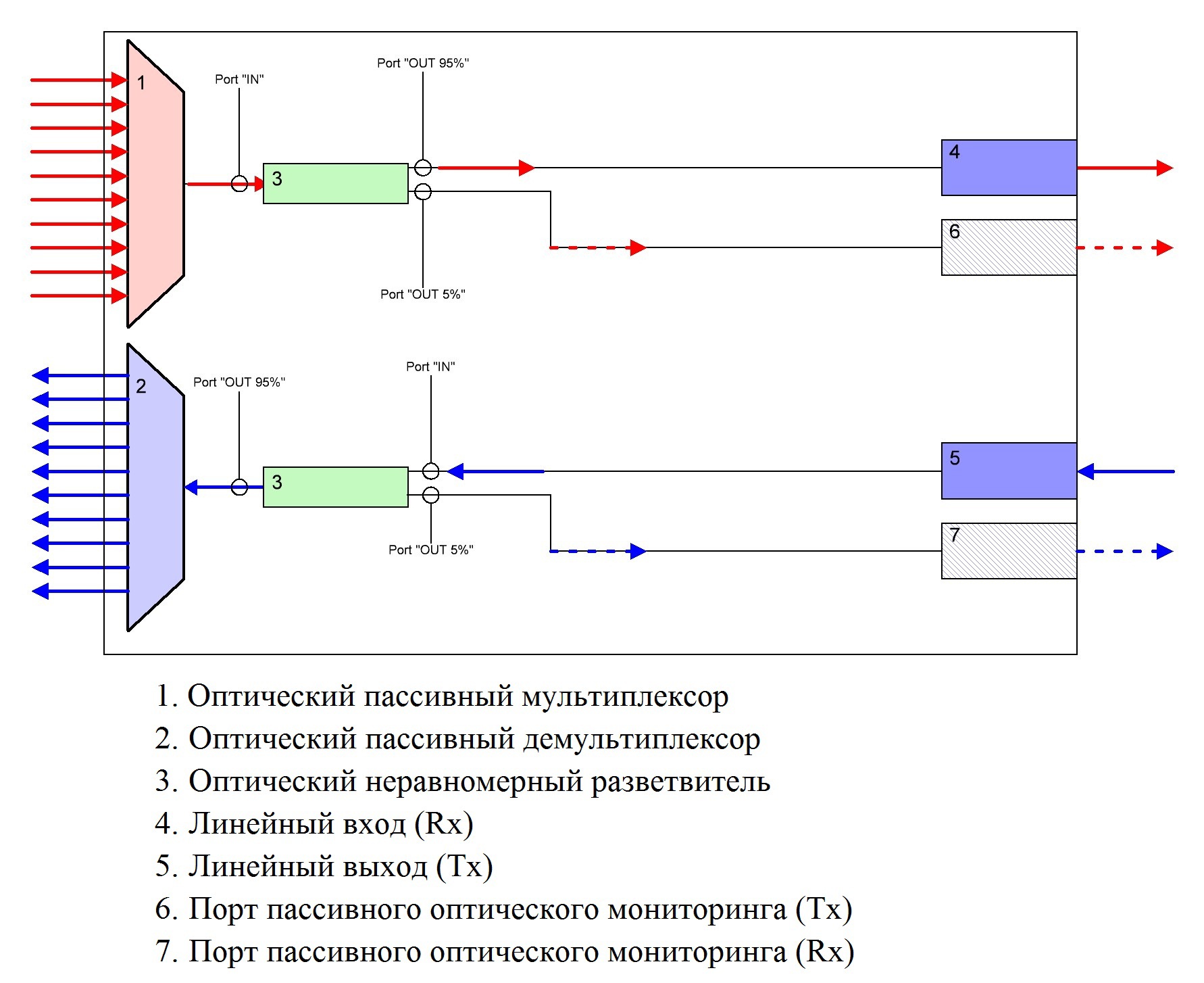
Fig. one
')
Often, only the optical port for connecting the measuring equipment is organized, since the installation of photodiodes entails not only the development of the power supply issue, but also the development of a control board, even if it is the simplest. And given the fact that a broadband photodetector can detect only the group level of the signal, there is not much use of this information, and therefore the costs are meaningless. For a long time, the role of the connected equipment was either the simplest optical power meters (examples of equipment and detailed information about them by reference), and in this case the measurement was of an estimated nature, the presence or absence of "light" (as in the case of embedded photodiodes), or expensive spectrum analyzers (examples of equipment and detailed information about them by reference), with the help of which precision measurements were made not only of the optical signal powers, but in principle the quality of the spectra of the transmitted or filtered signal in the system, depending on the test site.
At the beginning of the two thousandth, when the dimensions of optical compaction devices began to miniaturize, WDM optical power testers began to appear on the market of measuring equipment (examples of equipment and detailed information about them by reference and link ). These devices are much easier to use, unlike spectrum analyzers and have the size and measurement principle of conventional optical power meters, but they allow to measure each carrier in the selected WDM range. All measurement results are displayed on the LCD of the device and can be saved. Thus, measurements of rejected test signals have become much easier.
The main disadvantage of passive monitoring is that a very small optical signal is allocated to test leads, which entails two main problems:
• The final value must be calculated taking into account the percentage division of the coupler;
• Large measurement error associated with all the same low power output.
It should also be noted that in order to make measurements it is necessary to have in the arsenal good measuring equipment, as well as a large staff of service personnel who not only knows how to use measuring equipment, but is also very mobile (since for a frequent provider there are not only one transmission line built on WDM technology). The main advantage of such monitoring is the simplicity and cost effectiveness of implementation (measuring equipment and qualified staff are not taken into account).
At the moment there are two solutions for active monitoring of passive WDM components:
• Multiplexer with built-in active monitoring system;
• Tunable multiplexers - ROADM (this type of device is quite complex and has many implementations "in hardware", a separate article will be devoted to it).
A multiplexer with built-in active monitoring system allows simultaneous monitoring of the optical power levels of all incoming signals (from the client side and from the linear) to the multiplexer.
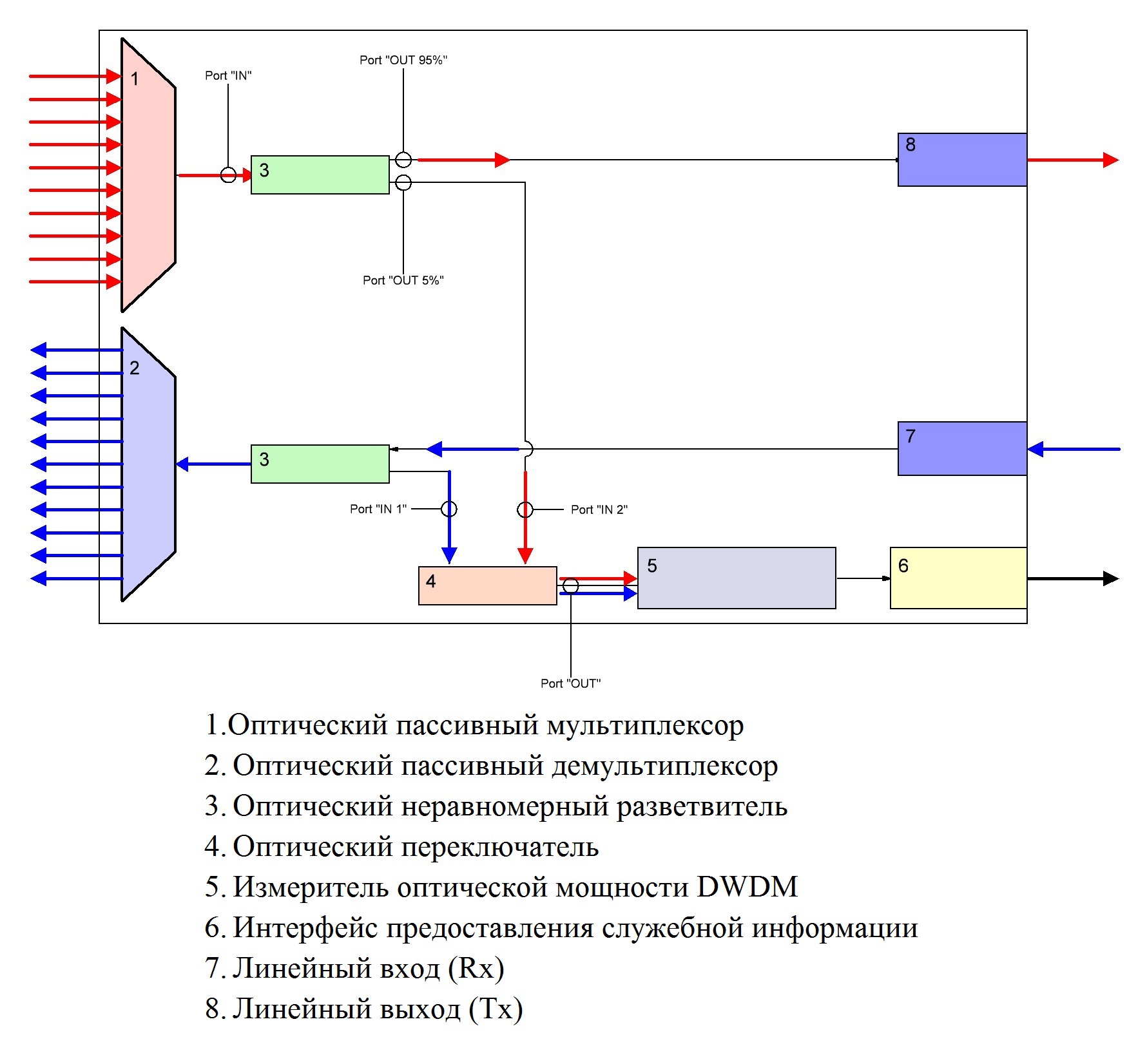
Fig. 2
The scheme for building a multiplexer with an active monitoring unit repeats in many ways the scheme for implementing the simplest passive monitoring using a WDM optical signal tester. To remove the test signal, non-uniform dividers are used (in Fig. 2 it is marked “3”). Next, the test signal enters an optical switch of type 2x1 (in Fig. 2, marked “5”), which selects which of the two test signals will go to the optical power meter.
The optical power meter consists of an Athermal AWG demultiplexer (in more detail about the multiplexer device in the first part of the article ) and a CCD matrix glued into the output focusing plate. Below is a photograph of a similar unit for CWDM signals; in the case of CWDM, thin film filters and photodiodes are used. The principle of operation of this optical power measurement unit is quite simple: The measured group signal is fed to the input optical port, then the signal hits the focusing green lens (for more information on thin-film filters and the green lens in particular, by reference ), which focuses the signal to the first an optical filter, then a system of mirrors with the use of additional skip filters, the group signal is divided into separate wavelengths and received by photodetectors. Information from photo detectors is transmitted to the resolver, and then to the client in one form or another.

Pic.3
Accordingly, an optoelectronic conversion occurs in the meter and the monitoring board receives information about the power level of each of the incoming signals at a given time. Further, this information is transmitted to the client program.
In principle, the optical switch can be excluded from the circuit and instead install another meter, but this step increases the cost of the device by 1.5 times.
In connection with the above construction architecture features (a sufficiently small signal size ≤5% is allocated to the measurement unit), the monitoring system has a measurement error ≤ ± 0.8dB. This measurement error value is calculated for the demultiplexer (marked 2 in Fig. 2) and is maximum, since the incoming signals are very low-power, the average value is -18 ... -8 dBm (the output optical power per measuring unit is -31 ... -21 dB). While for a multiplexer (marked “1” in Fig. 2), the measurement error will be ≤ ± 0.2dB, since the diverted optical power is -15 ... -12dB, which is a normal value for FOCL measuring equipment.
The main difference and plus of the active monitoring system is the use of the client program, which allows you to remotely receive operational information to the operator, which simplifies working with the compaction system and does not require the presence of service personnel in the immediate vicinity of the equipment. It should also be noted that the multiplexer’s monitoring function simplifies installation and does not require additional measuring equipment during installation and switching of the system as a whole.
At the moment, the start of sales of multiplexers with an active monitoring system was announced by several medium-sized manufacturers of telecommunications equipment in Europe (including Russia!) And South Korea. These devices have reached the Russian market only in the form of brief press releases, but there is no doubt that in the coming year the volume of supply of such equipment in the niche market segment will grow with a geometrical progression.
Source: https://habr.com/ru/post/250709/
All Articles