Wiring diagrams with LaTeX and TikZ
Sometimes in LaTeX you need to draw a simple electrical circuit. The following is a description of how to do this without using third-party software using LaTeX itself. What will be written further is designed for those who are already familiar with such a vector tool for LaTeX as TikZ. Otherwise, you must first familiarize yourself with TikZ. Some information in Russian is here . Those who are already familiar with TikZ - see under the cat. These methods of drawing schemes in LaTeX I used in the process of writing a thesis.
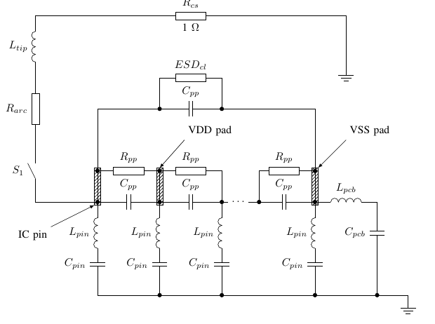
Such a scheme can be drawn using LaTeX tools:
For drawing electrical circuits is a library circuits. It must be connected in the document preamble using the \ usetikzlibrary command. Additionally, you must specify the tikzpicture environment parameter
circuit ee IEC.
')
Schema elements are special types of nodes in this library and are specified as regular TikZ nodes with the \ node command. Here you need to note that the node text, specified in curly brackets, is always empty for radio elements. The reference designation and denomination are entered as an info parameter in square brackets. The point up parameter rotates the component 90 degrees, and the point down parameter rotates 270 degrees.
A complete list of all components is available in the TikZ documentation.
The schematic node is specified by the special contact node, which draws a filled circle.
Wires between elements are set as usual in TikZ with the / draw command. Straight wire is drawn by the command
A wire at an angle of 90 degrees is drawn by the command:
or
The difference is that in the first case the wire first runs vertically and then horizontally, and in the second case - vice versa.
All parameters can be applied to the wires (arrows, line thickness, as well as to normal trajectories. For example, a thick wire with an arrow:
Schemes can be combined with any TikZ graphics and, for example, put a graph on the diagram.
Now we will consider a small example which is supplied with comments.
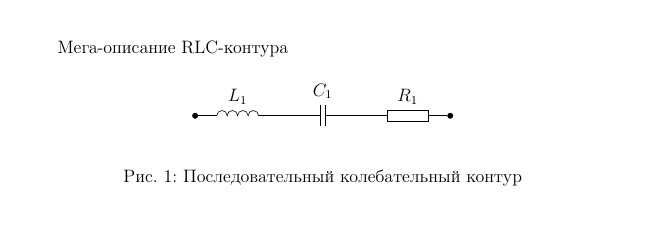
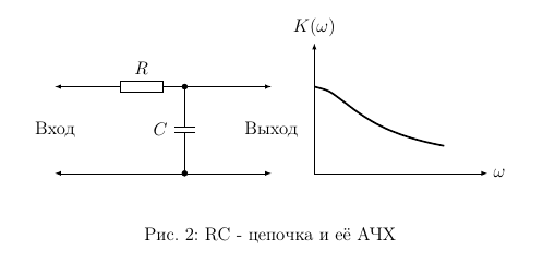
The result looks like this:
The circuitikik package is a further development of the cirtuits library. The package contains much more components: passive components, transistors, diodes, thyristors, logic gates, transformers. The circuitikz package is incompatible with the circuits library. You can not use them together. Package documentation can be downloaded here.
The circuitikz package connects in the preamble like this:
With such parameters, UGOs are obtained closest to our guests.
The package defines the special environment in which you want to put the schema:
Putting this environment inside tikzpicture is not necessary.
The ideology of drawing circuits is different from the circuits library. Components are not nodes, but paths. To place a single component, you need to create a path with the / draw command. The rotation of the component is carried out by the orientation of the path. As an example, consider the circuit of a thyristor phase regulator.
The result is the following:
For drawing circuits in LaTeX, you can use the circuits library for TikZ or the circuitikz package. I would recommend the last packet just for drawing complex circuits with semiconductor components. I usually prefer to use the circuits library. The diagrams made using each of these methods do not look alien in LaTeX, the same font and lines are used as in the rest of the document. Also, all the illustrations are embedded in the document and everything is stored in a single file.
The disadvantage is that large schemes slow down the compilation of the document, since each time they are compiled they are rendered anew. Also, drawing a scheme with TikZ means takes more time than using visual editors.
Resources:
Such a scheme can be drawn using LaTeX tools:
TikZ with a library of circuits
For drawing electrical circuits is a library circuits. It must be connected in the document preamble using the \ usetikzlibrary command. Additionally, you must specify the tikzpicture environment parameter
circuit ee IEC.
')
\usetikzlibrary{circuits} \usetikzlibrary{circuits.ee} \usetikzlibrary{circuits.ee.IEC} \usetikzlibrary{circuits.logic.IEC} Schema elements are special types of nodes in this library and are specified as regular TikZ nodes with the \ node command. Here you need to note that the node text, specified in curly brackets, is always empty for radio elements. The reference designation and denomination are entered as an info parameter in square brackets. The point up parameter rotates the component 90 degrees, and the point down parameter rotates 270 degrees.
\node (R) [resistor={info={$R$}}] at (2,2) {}; % \node (C1) at (3,0) [point up,capacitor={info = $C_1$, info'= 100 }] {}; % A complete list of all components is available in the TikZ documentation.
The schematic node is specified by the special contact node, which draws a filled circle.
\node (p2) [contact] at (6,-2) {}; % x=6, y=-2 Wires between elements are set as usual in TikZ with the / draw command. Straight wire is drawn by the command
\draw (R1) -- (C1); A wire at an angle of 90 degrees is drawn by the command:
\draw (R1) |- (C1); or
\draw (R1) -| (C1); The difference is that in the first case the wire first runs vertically and then horizontally, and in the second case - vice versa.
All parameters can be applied to the wires (arrows, line thickness, as well as to normal trajectories. For example, a thick wire with an arrow:
\draw [thick,->] (R1) -| (C1); Schemes can be combined with any TikZ graphics and, for example, put a graph on the diagram.
Now we will consider a small example which is supplied with comments.
\documentclass[12pt]{article} \usepackage{mathtext} \usepackage[T2A]{fontenc} \usepackage[koi8-r]{inputenc} \usepackage[russian]{babel} \usepackage[pdftex]{graphics} \usepackage{tikz} \usetikzlibrary{circuits} % , \usetikzlibrary{circuits.ee} % \usetikzlibrary{circuits.ee.IEC} \usetikzlibrary{arrows} % \usetikzlibrary{patterns} % \begin{document} - RLC- \begin{figure}[!h] \begin{center} \begin{tikzpicture}[circuit ee IEC] % circuit ee IEC \node (in) at (0,0) [contact] {}; % - \node (L1) at (1,0) [inductor={info = $L_1$, info'= 47 }] {}; % - % info - , info' - \node (C1) at (3,0) [capacitor={info = $C_1$, info'= 100 }] {}; % \node (R) at (5,0) [resistor={info = $R_1$, info'= 2 }] {}; % \node (out) at (6,0) [contact] {}; % \draw (in) -- (L1) -- (C1) -- (R) -- (out); % \end{tikzpicture} \end{center} \caption{ } \end{figure} \begin{figure}[!h] \begin{center} \begin{tikzpicture}[circuit ee IEC] \node (R) [resistor={info={$R$}}] at (2,2) {}; % \node (p1) [contact] at (3,2) {}; % R \node (C) [point up, capacitor={info={$C$}}] at (3,1) {}; % 90 \node (p2) [contact] at (3,0) {}; % \draw [-latex] (p1) -- (5,2); % , R \draw [latex-] (0,2) -- (R); \draw (R) -- (p1) -- (C) -- (p2); % \draw [latex-] (0,0) -- (p2); \draw [-latex] (p2) -- (5,0); \node at (0,1) {}; % \node at (5,1) {}; % % \draw[xshift=60mm,-latex] (0,0) -- (4,0) node [anchor=west] {$\omega$}; % \draw[xshift=60mm,-latex] (0,0) -- (0,3) node [anchor=south] {$K(\omega)$}; % Y \draw [very thick,xshift=60mm, y=2cm, x=1cm, declare function={K(\w)=1/sqrt(1+\w^2);}] plot [domain=0:3, samples=10, smooth] (\x,{K(\x)}); % \end{tikzpicture} \end{center} \caption{RC - } \end{figure} \end{document} The result looks like this:
Package circuitikz
The circuitikik package is a further development of the cirtuits library. The package contains much more components: passive components, transistors, diodes, thyristors, logic gates, transformers. The circuitikz package is incompatible with the circuits library. You can not use them together. Package documentation can be downloaded here.
The circuitikz package connects in the preamble like this:
\usepackage[europeanresistors,americaninductors]{circuitikz} With such parameters, UGOs are obtained closest to our guests.
The package defines the special environment in which you want to put the schema:
\begin{circuitikz} \end{circuitikz} Putting this environment inside tikzpicture is not necessary.
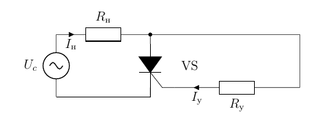
The ideology of drawing circuits is different from the circuits library. Components are not nodes, but paths. To place a single component, you need to create a path with the / draw command. The rotation of the component is carried out by the orientation of the path. As an example, consider the circuit of a thyristor phase regulator.
\begin{circuitikz} \draw (-1,0) to [sV,l=$U_c$] (-1,2) % to [R, l=$R_$,i>_=$I_$] (2,2) % to [Ty,l={VS},*-,n=VS] (2,0); % \draw (VS.G) to [R,mirror,l=$R_$,i<_=$I_$] ++(4,0) |- (2,2); \draw (VS.cathode) |- (-1,0); \end{circuitikz} The result is the following:

findings
For drawing circuits in LaTeX, you can use the circuits library for TikZ or the circuitikz package. I would recommend the last packet just for drawing complex circuits with semiconductor components. I usually prefer to use the circuits library. The diagrams made using each of these methods do not look alien in LaTeX, the same font and lines are used as in the rest of the document. Also, all the illustrations are embedded in the document and everything is stored in a single file.
The disadvantage is that large schemes slow down the compilation of the document, since each time they are compiled they are rendered anew. Also, drawing a scheme with TikZ means takes more time than using visual editors.
Resources:
- More examples of circuitry implemented using TikZ and circuitikz: www.texample.net/tikz/examples/area/electrical-engineering
- Circuittikz documentation: texdoc.net/show.php?pkg=circuitikz
- List of free software for drawing electrical circuits: https://en.wikipedia.org/wiki/Wikipedia:WikiProject_Electronics/Programs
Source: https://habr.com/ru/post/250541/
All Articles