Visualization and decoding of data from magnetic ATM cards
The subject of interest of this publication is reading and decoding data from the second track of an ATM card in the context of a shortage of equipment and facilities.
To begin with I will give dry theoretical knowledge. If the theory is not interested, you can skip it.
The film or track is a plastic, with applied tiny (very small) particles of a ferromagnet - a substance with residual magnetization. A ferromagnet, besides the fact that it is damn fine and is not distinguishable in a school or repair microscope, it also has a shape similar to honeycombs, granules or crystals.
In the process of applying to the surface, it immediately passes orientation - that is, it rotates according to the lines of the magnetic field. This achieves some improvement in the magnetic properties of the track. Further the fixer and a protective layer is applied. Everything, they cannot physically change their position; changing the directions of the magnetic induction vectors (the same residual magnetization, magnetic lines) can now occur only at the molecular level. But do not think that the strip after manufacture immediately has magnetic properties. First, if they are, they are too small, and second, the directions of the vectors are randomly oriented and compensate for each other.
')
We bring such a strip into the zone of the magnetic field and wait. We are waiting for the energy horses to jump over the barrier and the magnetic induction vectors of these particles will not coincide in magnitude with the external magnetic field vectors, and the particles themselves will not accumulate some energy and become the most real permanent magnets. Everything, now with this strip you can attract nails and shock monkeys in the zoo.
There is some primary magnetization that translates the virgin path from a state of lethargy into a state of residual magnetization. For a complete picture, you need to consider a hysteresis picture; it reflects all possible magnetic states of our ferromagnets. Among which there are two states of complete demagnetization.
Now, closer to how everything happens when writing and reading on a real magnetic strip of a card.
The first. When recording, the head that creates the field near the magnetic strip actually creates the field not next to it, but in it. To understand this, you need to remember a simple rule: the current flows along the path of least resistance. And now let's imagine a horseshoe, yes, an ordinary horseshoe from a horse. It has an incision; lean the horseshoe with a tear perpendicular to the strip. This is the modern head for such records. That is the whole point of the gap, which almost touches the magnetic strip.
We wrap the horseshoe with wire and let the electric current, the horseshoe will become an electromagnet, the magnetic field will flow along the horseshoe and in the place of the horseshoe break will meet strong resistance - air or some specially insulated dielectric.
What remains to do the magnetic field? Take the path of least resistance - on the most magnetic strip! Jumping on a strip, withdraw through it. What is good for us.
The way of representing discrete (consider in the future - digital information) on such a strip can theoretically be very different. You can substitute yourself in the constructor's place and try to simulate the processes of writing and reading. At the same time in our hands the following trumps:
- information needs to be recorded in sections of fixed length;
- it is possible to record 2 types of sections on a strip, that is, with different directions of magnetic field lines (magnetic induction vectors and heaps of other quantities, which, however, we don't care). For simplicity, we denote them as SN and NS;
- it is possible to record types of SN and NS sections on a strip, but any of them may have different degrees of magnetization, that is, you can designate a gradation of the degree of magnetization for any of the sections, for example, by agreeing with you that we will assign a number from 0 to 9 to the right expressing the degree of magnetization in increasing;
- reading is possible under the condition of a change in the magnetic flux of the head, which passes near the magnetized strip. The changing magnetic flux passes through the core (all the same horseshoe itself) and as a result, a varying voltage appears at the terminals of the winding located on the core.
Thus, it can only change when the magnetic flux changes. And it can change in three cases:
a) changing the directions of the magnetic field lines. That is, the plots should go in this order:
(SN) (NS) (SN). As a result, we get, roughly speaking, 2 times the pulsating current;
b) the change in the intensity of the magnetic fields of the plots. For example, such a sequence of sections should cause the appearance / change of electric current in the head - (SN1) (SN2) (SN9) (SN3) (3 changes in the amplitude of the electric current of the head), but this is no longer - (SN5) (SN5) (SN5) (SN5) (SN5);
c) combination of a and b (SN5) (NS5) (NS6).
It seems there is no problem, take it, use any of the options to represent the zeros of discrete sections. Yes, it's easy to record. Problems appear when reading. One of the main factors that puts sticks in the wheels is the speed of reading, that is, the speed of pulling the tape under the head. Manually invented devices for manually dragging a card through them cannot afford to accurately recognize the speed without additional tricks with which the hand draws the card (this is possible, but an additional clock magnetic or other line must be made). ATMs are simpler and sufficient accuracy can be realized.
So what's the problem? Well, a different speed and figs with her.
And you try, being a simple ordinary device, disassemble the following sequence:
(SN) (NS) (NS) (SN) (NS)? (sequence 1)
(1) (2) (3) (4) (5)
What can be said about this sequence? Only that which will cause exactly 3 times (between sections 1 and 2, 3 and 4, 4 and 5) will change the polarity of the electric field in the head.
If we take the very first coding option 0 and 1 that changes the polarity of the magnetic field sections, then we can confidently say that SN is 1, and NS is 0, and if we get a voltage jump to the + side, we can say that the transition from 1 to 0. So, 2 plots are recognized. But further, where 2 and 3 are next to each other - (NS) (NS) there will be no change, but it is known that the last thing on this place that was recognized by the previous voltage surge is 0! But try, prove how many exactly zeros in this area at different speeds, two or more. That sequence 1 is sequence 1, and not, say, this:
(SN) (NS) (NS) (NS) (NS) (SN) (NS)? (sequence 2)
(1) (2) (3) (error) (error) (4) (5)
Between 3 and 4 everything is smooth - a voltage surge occurs in the direction - and we can say that 3 is 0, and 4 is 1. There are a lot of exits from the current situation, from the synchronization line to the frequency coding. Which is the main one in magnetic cards is the doubling of the frequency F \ 2F.
(NS) (SN) (NS) (NS) (SN) (SN) (NS) (SN) (NS) (SN)
(1) (0) (0) (1) (1)
The meaning, I think, is clear. For coding 1, the fact of the interpretation of voltage surges is used - doubling the frequency of polarity reversal of the sections for coding one element. If you look better, you can see that such encoding completely eliminates the disadvantages of the encoding presented above under certain conditions.
Suppose we stop the map at the site (NS) (NS). You might think that the device will fail and incorrectly calculate the number of zeros, that is, it will take (NS) (NS) (NS) (NS) per 00. In fact, this will not happen, because during coding the condition for switching to the next group of sections is a change of polarity , and it does not occur and the device simply puts 0 and waits for a change in polarity (waits at least indefinitely) in order to restart its counter - the generator to recognize the next group of sections. The question of how the device determines the frequency of occurrence of polarity shifts is, of course, interesting, but not necessary now.
It is better to see once than read a hundred times. We will look at the contents of the magnetic card tracks and see if it is possible at home to unambiguously understand what is written on them. Along the way, getting some tool for visual assessment of the tracks.
Sawdust sprinkled on a sheet of paper, under which there is a magnet, line up along the lines of force. We need from them that they stick to the magnetized sections of the map’s tracks, exposing the treacherous ones.
Ordinary sawdust or metal dust will not work, too large particles. It is proposed to use toner particles for printer cartridges. They are very carefully processed, homogeneous, and some of them are composed of magnetic pigments.
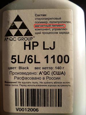
In the original sources, ideas are proposed to use a mixture of toner and starch, but this is apparently due to the fact that the idea of assessing the state of the cards using toner or a special spray appeared long ago, and then the toners were specific. Therefore, for example, we should not be leveled at France from 1999. We will go to a modern store and purchase toner with magnetic pigments (as shown in the figure), preferably colored.
Having sprinkled the map and knocking it on the table to shake off excess toner, we get this newly discovered world at our disposal. On the strip you immediately see all the defects of the sections received by the card. In some domestic cases, this may be useful.
We must continue. The whole interest is in reading the contents of the card with only a camera, a magnifying glass, or of course a microscope. As will be clear further, for the analysis of the second track from the 3rd enough camera. The pictures show pictures from an average digital camera and from a digital microscope.

The entire track number 2 (ABA) entirely.
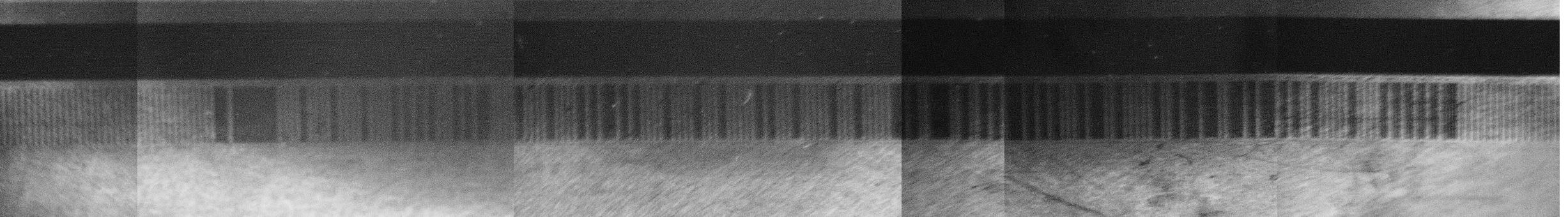
The entire track No. 2 (ABA) is entirely with landmarks in the paint program.

And the same path, slightly larger:

For convenience, of course, use images from a microscope.
So, the analysis. But first you need to refer to the standards:
ISO 7810 Physical Characteristics of Credit.Card Size Document
ISO 7811-1 Embossing
ISO 7811-2 Magnetic Stripe - Low Coercivity
ISO 7811-3 Location of Embossed Characters
ISO 7811-4 Location of Tracks 1 and 2
ISO 7811-5 Location of Track 3
ISO 7811-6 Magnetic Stripe - High Coercivity
ISO 7813 Financial Transaction Cards
Further in the right side of the document we look from top to bottom:
- The drawing of the map and its dimensions are 3.375 × 2.125 inches, one inch = 2.54 cm, it turns out 85 * 54 mm. Coincides with the size of the investigated card.
- The line “Magnetic Stripe Encoding - Financial Transaction Cards” shows the distance from the edge of the card in inches and the characteristics of the tracks (track) as a kind of table. There are 3 tracks, each has its own name:
TRACK 1 IATA
TRACK 2 ABA
TRACK 3 THRIFT
RECORDING DENSITY (bits per inch) recording density for each of the tracks.
CHARACTER CONFIGURATION (including parity bit) "Device character", in fact, the number of bits per byte, taking into account the parity bit and INFORMATION CONTENT (including control characters) the contents of characters. It is seen that the first track contains both numbers and letters, the second and third contain only numbers - 40 numeric characters.
Below and to the left are the decoding of the track formats.
In theory, our 2nd ABA track should contain no more than 75 bits per inch. That is no more than 3.375 (card length) * 75 (capacity per inch) = 253.125 bits = 253 bits for the entire track. The byte size is 5 bits, the encoding is only a digit, and 253/5 = 50 characters are obtained, but by the standard there are 40. The extra ones are sequences for synchronization at the very beginning of the track - zeroes.
5 bit coding is described in the link below.
Well, to start, you have to start. Having a decoding table, we will write a decryption program on-line. And yes, we also need a dump obtained during the visualization, there it is (of course, slightly modified to hide personal data, which, by the way, the cat wept there):
000000000000000000000000000000000000000110111111100001000010000100001010101000101011000010000100001010110101000010000100010000010100010000010001000001101001110010010101101010100010110010000010010110110011010110101001000001000010101010101100000000000000000000
Well, the program itself:
And finally, the result itself:
S5224559648685547M08081211550005850000EM ...
Which suspiciously resembles the numbers and letters scribed on the card.
The next track is already encrypted, but this is another time.
ru.wikipedia.org/wiki/Hysteresis
www.dataip.co.uk/Reference/MagneticCardBCD.php
stripesnoop.sourceforge.net/devel/layoutstd.pdf
Patrick Goll's book - Magnetic cards and PC.
To begin with I will give dry theoretical knowledge. If the theory is not interested, you can skip it.
The film or track is a plastic, with applied tiny (very small) particles of a ferromagnet - a substance with residual magnetization. A ferromagnet, besides the fact that it is damn fine and is not distinguishable in a school or repair microscope, it also has a shape similar to honeycombs, granules or crystals.
In the process of applying to the surface, it immediately passes orientation - that is, it rotates according to the lines of the magnetic field. This achieves some improvement in the magnetic properties of the track. Further the fixer and a protective layer is applied. Everything, they cannot physically change their position; changing the directions of the magnetic induction vectors (the same residual magnetization, magnetic lines) can now occur only at the molecular level. But do not think that the strip after manufacture immediately has magnetic properties. First, if they are, they are too small, and second, the directions of the vectors are randomly oriented and compensate for each other.
')
We bring such a strip into the zone of the magnetic field and wait. We are waiting for the energy horses to jump over the barrier and the magnetic induction vectors of these particles will not coincide in magnitude with the external magnetic field vectors, and the particles themselves will not accumulate some energy and become the most real permanent magnets. Everything, now with this strip you can attract nails and shock monkeys in the zoo.
There is some primary magnetization that translates the virgin path from a state of lethargy into a state of residual magnetization. For a complete picture, you need to consider a hysteresis picture; it reflects all possible magnetic states of our ferromagnets. Among which there are two states of complete demagnetization.
Now, closer to how everything happens when writing and reading on a real magnetic strip of a card.
The first. When recording, the head that creates the field near the magnetic strip actually creates the field not next to it, but in it. To understand this, you need to remember a simple rule: the current flows along the path of least resistance. And now let's imagine a horseshoe, yes, an ordinary horseshoe from a horse. It has an incision; lean the horseshoe with a tear perpendicular to the strip. This is the modern head for such records. That is the whole point of the gap, which almost touches the magnetic strip.
We wrap the horseshoe with wire and let the electric current, the horseshoe will become an electromagnet, the magnetic field will flow along the horseshoe and in the place of the horseshoe break will meet strong resistance - air or some specially insulated dielectric.
What remains to do the magnetic field? Take the path of least resistance - on the most magnetic strip! Jumping on a strip, withdraw through it. What is good for us.
The way of representing discrete (consider in the future - digital information) on such a strip can theoretically be very different. You can substitute yourself in the constructor's place and try to simulate the processes of writing and reading. At the same time in our hands the following trumps:
- information needs to be recorded in sections of fixed length;
- it is possible to record 2 types of sections on a strip, that is, with different directions of magnetic field lines (magnetic induction vectors and heaps of other quantities, which, however, we don't care). For simplicity, we denote them as SN and NS;
- it is possible to record types of SN and NS sections on a strip, but any of them may have different degrees of magnetization, that is, you can designate a gradation of the degree of magnetization for any of the sections, for example, by agreeing with you that we will assign a number from 0 to 9 to the right expressing the degree of magnetization in increasing;
- reading is possible under the condition of a change in the magnetic flux of the head, which passes near the magnetized strip. The changing magnetic flux passes through the core (all the same horseshoe itself) and as a result, a varying voltage appears at the terminals of the winding located on the core.
Thus, it can only change when the magnetic flux changes. And it can change in three cases:
a) changing the directions of the magnetic field lines. That is, the plots should go in this order:
(SN) (NS) (SN). As a result, we get, roughly speaking, 2 times the pulsating current;
b) the change in the intensity of the magnetic fields of the plots. For example, such a sequence of sections should cause the appearance / change of electric current in the head - (SN1) (SN2) (SN9) (SN3) (3 changes in the amplitude of the electric current of the head), but this is no longer - (SN5) (SN5) (SN5) (SN5) (SN5);
c) combination of a and b (SN5) (NS5) (NS6).
It seems there is no problem, take it, use any of the options to represent the zeros of discrete sections. Yes, it's easy to record. Problems appear when reading. One of the main factors that puts sticks in the wheels is the speed of reading, that is, the speed of pulling the tape under the head. Manually invented devices for manually dragging a card through them cannot afford to accurately recognize the speed without additional tricks with which the hand draws the card (this is possible, but an additional clock magnetic or other line must be made). ATMs are simpler and sufficient accuracy can be realized.
So what's the problem? Well, a different speed and figs with her.
And you try, being a simple ordinary device, disassemble the following sequence:
(SN) (NS) (NS) (SN) (NS)? (sequence 1)
(1) (2) (3) (4) (5)
What can be said about this sequence? Only that which will cause exactly 3 times (between sections 1 and 2, 3 and 4, 4 and 5) will change the polarity of the electric field in the head.
If we take the very first coding option 0 and 1 that changes the polarity of the magnetic field sections, then we can confidently say that SN is 1, and NS is 0, and if we get a voltage jump to the + side, we can say that the transition from 1 to 0. So, 2 plots are recognized. But further, where 2 and 3 are next to each other - (NS) (NS) there will be no change, but it is known that the last thing on this place that was recognized by the previous voltage surge is 0! But try, prove how many exactly zeros in this area at different speeds, two or more. That sequence 1 is sequence 1, and not, say, this:
(SN) (NS) (NS) (NS) (NS) (SN) (NS)? (sequence 2)
(1) (2) (3) (error) (error) (4) (5)
Between 3 and 4 everything is smooth - a voltage surge occurs in the direction - and we can say that 3 is 0, and 4 is 1. There are a lot of exits from the current situation, from the synchronization line to the frequency coding. Which is the main one in magnetic cards is the doubling of the frequency F \ 2F.
(NS) (SN) (NS) (NS) (SN) (SN) (NS) (SN) (NS) (SN)
(1) (0) (0) (1) (1)
The meaning, I think, is clear. For coding 1, the fact of the interpretation of voltage surges is used - doubling the frequency of polarity reversal of the sections for coding one element. If you look better, you can see that such encoding completely eliminates the disadvantages of the encoding presented above under certain conditions.
Suppose we stop the map at the site (NS) (NS). You might think that the device will fail and incorrectly calculate the number of zeros, that is, it will take (NS) (NS) (NS) (NS) per 00. In fact, this will not happen, because during coding the condition for switching to the next group of sections is a change of polarity , and it does not occur and the device simply puts 0 and waits for a change in polarity (waits at least indefinitely) in order to restart its counter - the generator to recognize the next group of sections. The question of how the device determines the frequency of occurrence of polarity shifts is, of course, interesting, but not necessary now.
It is better to see once than read a hundred times. We will look at the contents of the magnetic card tracks and see if it is possible at home to unambiguously understand what is written on them. Along the way, getting some tool for visual assessment of the tracks.
Sawdust sprinkled on a sheet of paper, under which there is a magnet, line up along the lines of force. We need from them that they stick to the magnetized sections of the map’s tracks, exposing the treacherous ones.
Ordinary sawdust or metal dust will not work, too large particles. It is proposed to use toner particles for printer cartridges. They are very carefully processed, homogeneous, and some of them are composed of magnetic pigments.
In the original sources, ideas are proposed to use a mixture of toner and starch, but this is apparently due to the fact that the idea of assessing the state of the cards using toner or a special spray appeared long ago, and then the toners were specific. Therefore, for example, we should not be leveled at France from 1999. We will go to a modern store and purchase toner with magnetic pigments (as shown in the figure), preferably colored.
Having sprinkled the map and knocking it on the table to shake off excess toner, we get this newly discovered world at our disposal. On the strip you immediately see all the defects of the sections received by the card. In some domestic cases, this may be useful.
We must continue. The whole interest is in reading the contents of the card with only a camera, a magnifying glass, or of course a microscope. As will be clear further, for the analysis of the second track from the 3rd enough camera. The pictures show pictures from an average digital camera and from a digital microscope.
The entire track number 2 (ABA) entirely.
The entire track No. 2 (ABA) is entirely with landmarks in the paint program.
And the same path, slightly larger:
For convenience, of course, use images from a microscope.
So, the analysis. But first you need to refer to the standards:
ISO 7810 Physical Characteristics of Credit.Card Size Document
ISO 7811-1 Embossing
ISO 7811-2 Magnetic Stripe - Low Coercivity
ISO 7811-3 Location of Embossed Characters
ISO 7811-4 Location of Tracks 1 and 2
ISO 7811-5 Location of Track 3
ISO 7811-6 Magnetic Stripe - High Coercivity
ISO 7813 Financial Transaction Cards
Further in the right side of the document we look from top to bottom:
- The drawing of the map and its dimensions are 3.375 × 2.125 inches, one inch = 2.54 cm, it turns out 85 * 54 mm. Coincides with the size of the investigated card.
- The line “Magnetic Stripe Encoding - Financial Transaction Cards” shows the distance from the edge of the card in inches and the characteristics of the tracks (track) as a kind of table. There are 3 tracks, each has its own name:
TRACK 1 IATA
TRACK 2 ABA
TRACK 3 THRIFT
RECORDING DENSITY (bits per inch) recording density for each of the tracks.
CHARACTER CONFIGURATION (including parity bit) "Device character", in fact, the number of bits per byte, taking into account the parity bit and INFORMATION CONTENT (including control characters) the contents of characters. It is seen that the first track contains both numbers and letters, the second and third contain only numbers - 40 numeric characters.
Below and to the left are the decoding of the track formats.
In theory, our 2nd ABA track should contain no more than 75 bits per inch. That is no more than 3.375 (card length) * 75 (capacity per inch) = 253.125 bits = 253 bits for the entire track. The byte size is 5 bits, the encoding is only a digit, and 253/5 = 50 characters are obtained, but by the standard there are 40. The extra ones are sequences for synchronization at the very beginning of the track - zeroes.
5 bit coding is described in the link below.
--Data Bits-- Parity b1 b2 b3 b4 b5 Character Function 0 0 0 0 1 0 (0H) Data 1 0 0 0 0 1 (1H) " 0 1 0 0 0 2 (2H) " 1 1 0 0 1 3 (3H) " 0 0 1 0 0 4 (4H) " 1 0 1 0 1 5 (5H) " 0 1 1 0 1 6 (6H) " 1 1 1 0 0 7 (7H) " 0 0 0 1 0 8 (8H) " 1 0 0 1 1 9 (9H) " 0 1 0 1 1 : (AH) Control 1 1 0 1 0 ; (BH) Start Sentinel 0 0 1 1 1 < (CH) Control 1 0 1 1 0 = (DH) Field Separator 0 1 1 1 0 > (EH) Control 1 1 1 1 1 ? (FH) End Sentinel Well, to start, you have to start. Having a decoding table, we will write a decryption program on-line. And yes, we also need a dump obtained during the visualization, there it is (of course, slightly modified to hide personal data, which, by the way, the cat wept there):
000000000000000000000000000000000000000110111111100001000010000100001010101000101011000010000100001010110101000010000100010000010100010000010001000001101001110010010101101010100010110010000010010110110011010110101001000001000010101010101100000000000000000000
Well, the program itself:
.686 ; create 32 bit code .model flat, stdcall ; 32 bit memory model option casemap :none ; case sensitive include \masm32\include\windows.inc include \masm32\include\masm32.inc include \masm32\include\gdi32.inc include \masm32\include\user32.inc include \masm32\include\kernel32.inc include \masm32\include\shell32.inc includelib \masm32\lib\masm32.lib includelib \masm32\lib\gdi32.lib includelib \masm32\lib\user32.lib includelib \masm32\lib\kernel32.lib .data? .data Handle_File_Input dd 0 Handle_File_Result dd 0 InputFile db "Content_track_2.txt", 0 ResultFile db "Result.txt", 0 flStr OFSTRUCT <> NBW dd ? , 0 NBR dd ?, 0 title_box db "[ABA] track-decoder", 0 ms1 db " : [Start_Sentinel] , . - ?", 0 ms2 db " - ", 0 ms3 db " Content_track_2.txt", 0 ms4 db " , Result.txt. , .", 0 bet db 254 dup (030h) en db 0ffh Start_Sentinel db "1010", 0ffh ; ;bet db "00000000000000000000000000000000000000011011111110000100001000010000101010100010101100001000010000101011010100001000010001000001010001000001000100000" ;bey db "110100111001001010110101010001011001000001001011011001101011010100100000100001010101010110000000000000000" result db 60 DUP(0) val_0 db '.' ;00000 val_1 db 030h ;00001 - val_2 db 038h ;00010 - val_3 db '?' ;00011 val_4 db 034h ;00100 - val_5 db '?' ;00101. val_6 db '?' ;00110 val_7 db '?' ;00111 val_8 db 032h ;01000 - val_9 db '?' ;01001 val_10 db '?' ;01010 val_11 db '?' ;01011 val_12 db '?' ;01100 val_13 db 036h ;01101 - val_14 db '?' ;01110 val_15 db '?' ;01111 val_16 db 031h ;10000 - val_17 db '?' ;10001 val_18 db '?' ;10010 val_19 db 039h ;10011 - val_20 db '?' ;10100 val_21 db 035h ;10101 - val_22 db 'M' ;10110 - val_23 db '?' ;10111 val_24 db '?' ;11000 val_25 db 033h ;11001 - val_26 db 'S' ;11010 - val_27 db '?' ;11011 val_28 db 037h ;11100 - val_29 db '?' ;11101 val_30 db '?' ;11110 val_31 db 'E' ;11111 - .code start: begin: push OF_READWRITE push offset flStr push offset InputFile call OpenFile cmp eax, 0ffffffffh ; jz ext ; mov dword ptr [Handle_File_Input], eax push FILE_BEGIN push NULL push 0 push eax call SetFilePointer ; push 0 push Handle_File_Input call GetFileSize mov ebx, 254 cmp eax, ebx ; . cmova eax, ebx ; 254 push NULL push offset NBW push eax push offset bet push Handle_File_Input call ReadFile ; lea esi, [en-1] ; lea edi, bet ; reverse: cmp esi, edi jbe end_reverse mov al, byte ptr [esi] mov ah, byte ptr [edi] mov byte ptr [edi], al mov byte ptr [esi], ah dec esi inc edi jmp reverse end_reverse: ;------ Start_Sentinel------------------------------------------- mov edi, offset bet mov al, 030h mov ecx, 0ffh repz scasb ; "1" mov edx, edi xor edx, offset [Start_Sentinel+1] ; jnz continue_1 push 0 push offset title_box push offset ms2 ; push 0 call MessageBoxA jmp ext continue_1: ;-- ( ) SS ;-- , - SS ( ) ;-- SS - xor edx, offset [Start_Sentinel+1] ; edx mov eax, edi mov ebx, offset Start_Sentinel search_SS: mov esi, eax inc eax mov ecx, -1 mov edi, ebx repz cmpsb ; ecx cmp cx, -6 loopnz search_SS dec eax ; eax sub eax, edx jz continue_2 ; SS push 4 push offset title_box push offset ms1 push 0 call MessageBoxA ; ;[ms+191] cmp eax, 1 jnz ext continue_2: mov byte ptr [result], 'S' ; dec esi ; SS mov ecx, 5 mov eax, offset [en-1] sub eax, esi xor edx, edx div ecx mov ecx, eax ; 5 mov edi, offset [result+1] mov ebx, offset val_0 pars: lodsd mov edx, eax lodsb sub al, 30h sub edx, 030303030h shl dl, 4 xor al, dl shl dh, 3 xor al, dh bswap edx shl dl, 1 xor al, dl shl dh, 2 xor al, dh xlat stosb loop pars push OF_READWRITE push offset flStr <habracut /> push offset ResultFile call OpenFile mov dword ptr [Handle_File_Result], eax push FILE_BEGIN push NULL push 0 push eax call SetFilePointer ; push NULL push offset NBW push 60 push offset result push dword ptr [Handle_File_Result] call WriteFile ext: push Handle_File_Input call CloseHandle push Handle_File_Result call CloseHandle push 4 push offset title_box push offset ms4 push 0 call MessageBoxA ; cmp eax, 6 jz begin exit: push 0 call ExitProcess end start And finally, the result itself:
S5224559648685547M08081211550005850000EM ...
Which suspiciously resembles the numbers and letters scribed on the card.
The next track is already encrypted, but this is another time.
useful links
ru.wikipedia.org/wiki/Hysteresis
www.dataip.co.uk/Reference/MagneticCardBCD.php
stripesnoop.sourceforge.net/devel/layoutstd.pdf
Patrick Goll's book - Magnetic cards and PC.
Source: https://habr.com/ru/post/250329/
All Articles