PIC16F1503. Wheelbarrow for pumping - 2. Light
It used to be about sound .
I left the last post unfinished. If you remember, I couldn’t manage to find “that sound”. Attempts to pick up “tsiferki on a whim” turned out to be much worse than the usual “pi-piu” ... On the one hand all the same - from the Chinese tweeter no sound is achieved, but on the other hand - “unclean work, low class. Again, drive the clock frequency at 16 MHz for the sake of this ...

')
In general, I did something wrong somewhere. The next evening, an educational program on music and its literacy gave rise to even more questions than it was before (like why there is C sharp, but there is no re-sharp, but instead E-flat instead?). But I’m no stranger to "taking the Japanese by the manual", so I continued to understand. Simultaneously with the customer they discussed the change of the TZ (a familiar picture, isn’t it?), Which consisted in adding a “bottom light”. To my timid attempts to say that this is actually a police car, an answer was received that it was a police car in the Negro quarter ...
First I decided to finish the sound. I changed the frequencies and PWM, set the divider by 1 to 255, got the frequencies 7692 Hz and 62 Hz. The range has changed a bit, but still - quite.
And then something pulled me to measure the frequency with a divider 128. I expected to get something like (7692-62) / 2 = 3815 Hz, but for some reason I received only 125 ... And then me, as my favorite programmers in sweaters with deer , it dawned on: who said that the frequency-divider dependence is linear? A couple of extra measurements showed that I am absolutely right. A little bit of trachybidoc with an oscilloscope and an Excel feature gave just such a beautiful picture of Hz-Timer (originals as usual, in the archive at the end of the post):
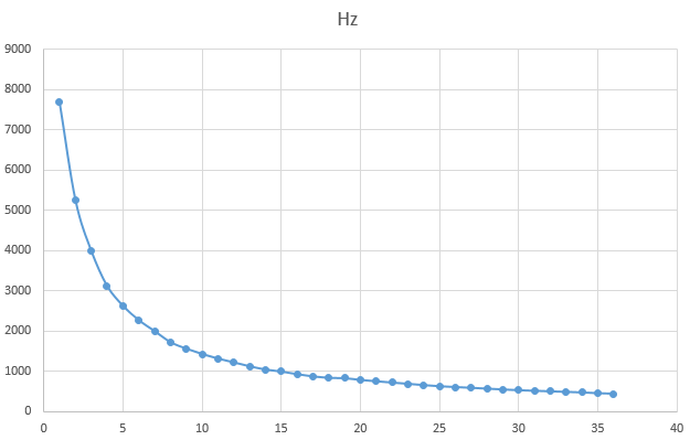
Now it became clear to me why my sounds were so terrible. Plus, in the comments, they remembered the door bells, where in 2KB of ROM they thrust melodies ... When you know what to look for, it is found quickly.
The first (like) such a scheme was published in the journal Radio, 92, 8th number. There was also a smart (for me) sign
And on the next page is the firmware itself. Even more googlezh and we find "Radio amateur", 93, February. There is absolutely the same principle, but there are more melodies.
Again, we charge the Excel (in the archive on the second tab) and transfer delays from “iron” to “soft”.
Add some code
And cheers! From the Chinese tweeter heard quite a recognizable sound that does not offend even my ears. In principle, we can be proud of ourselves - we repeated the 20-year scheme on “logic” on a new element base. So even if the machine is not playable, you can always convert it into a doorbell :)
In general, while the process of finding the best “wah-wow” continues, but in principle we have closed the problem of sound. Go to the light.
As I wrote in the first post, the native LEDs were blue and very bright. Plus, I was outraged that blue shines through a red light filter and breaks all harmony. So you need to change.
He took out a red LED from the stash, turned it on. The first problem: the brightness is different. Blue is very bright. Changing to “from the stash” is still different. Of course, you can mute additional resistors, but it is too simple. Finally got to the RGB LED and the miracle happened! It shines with all colors with the same brightness. In principle, it is not surprising, because it costs as much as fifty "cheapest".
It was decided that I would take four RGB LEDs for all needs (the red and blue parts of the chandelier, the headlights and the bottom). My LEDs have a common cathode, so I will need 3 (RGB) * 4 (pieces) - 12 legs for control. Again, the problem: the microcontroller has only 12 (in general, 14, but two power) legs, one of which is allocated exclusively “to the input” (it hangs on the reset) and we have taken one to the “music”. And somewhere you need to hang the switch and leave the stock.
Usually in such cases it is easy to do: they take and install some kind of “port extender”. The most common option is a shift register type 74HC595. But putting a second microcircuit alongside is a brute force and a complete budget overrun. If all projects do this, then there will be nothing left for pies ... And we at studiovsemoe.com really love to eat :)
Therefore, I will go the other way and do everything with the controller. Spreading legs (all on the way out) like this

And I connect the LEDs like this (as usual, the complete diagram is in the archive)
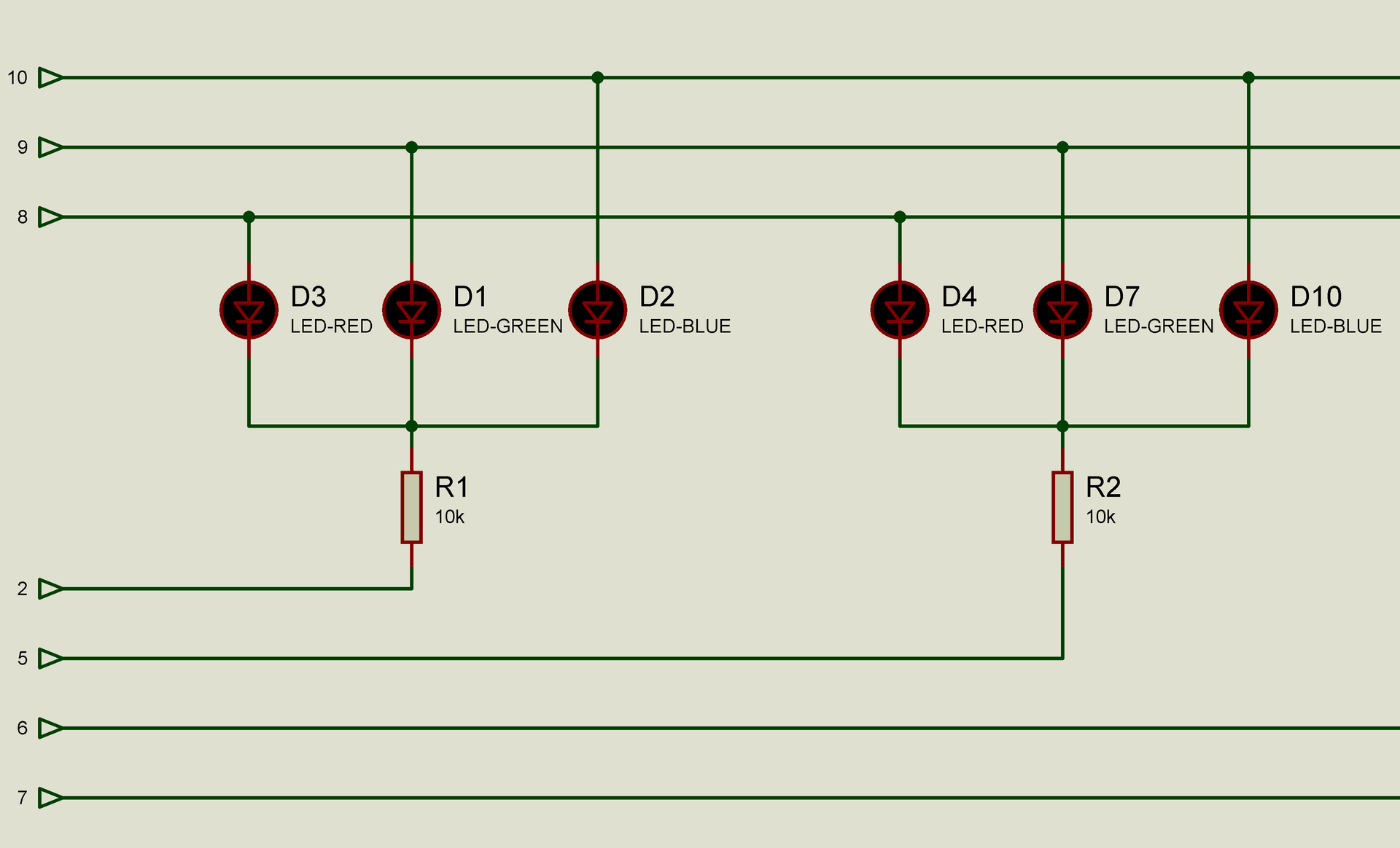
In the diagram, I “broke” each LED into three separate ones, so that the operating principle would be clear. Well, for some reason, the resistors are plugged into 10k, although in reality they are 200-300 Ohm. As a result, we have a 4x3 LED matrix.
Attention: this scheme is suitable only for 1-2-3 LEDs. If you plan to connect more - use a special driver like L298 - otherwise the current through the output of the chip will be too large.
Add some code
Here we set the legs of C0-C2 in one, and C3-C5 and A5 - in zero. If everything is correctly assembled, then all the LEDs with a “white light” should light up.
What happened? As you know, the current flows from a place with a high potential to a place with a low one. And we have on some legs 1 (or + 3V), and on the other - 0. That LED lights up. If on those and on those legs apply 0 or 1 - nothing will burn. By the way, the universality of the circuit also emerges from here - if you do not have LEDs with a common cathode, like mine, but with a common anode, then in the code it will be enough for you to change 0 to 1 and everything will work.
As a result, combining the state of the C0-C2 legs, we can choose the color of the glow, while others choose which LED lights up from 4x, for the total, instead of the original 12 legs, it cost 7y. Not very cool (you can get by with 2 shift registers), but for our purposes it is more than enough.
But we have at least two LEDs to be on at the same time and in different colors (for example, a chandelier and a headlight, a headlight and a bottom). Here I use the old as the world trick: I will quickly switch between the LEDs and turn on the necessary colors. If done quickly enough, the eye will not notice flicker.
We try to blink colors (I think, the meaning can be understood from the notation)
And we look how beautifully the LEDs blink, turning over the colors ...
In principle, you can rewrite to work directly with the port - it's easier.
What is the difference? The difference is. that the first option takes (with all the strapping) 89 bytes, and the second 81. 8 bytes of difference out of the blue. Well, the second is faster :)
If you do not understand, the design
Fully similar
Where are the cons? The downsides are that on some controllers, the high-order bits can be used for something useful, and we shove everything and use our dirty hands ...
Where else is the minus? Another disadvantage is that we again have to engage in "dragon race". Well, this is an unworthy business for talents like us. Don't bother doing this.
We have a timer that is responsible for the sound. No, we will not touch him, but we will touch his neighbors. For a change, take TIM1
How does it differ from TIM2? Firstly, greater accuracy - if TIM2 has a range divided into 255 parts, then here it is 65,535. So you can more accurately fall into the frequency. Secondly, he is not tied to anything and nothing is tied to him. And finally, its output can be brought to the foot of the microcontroller. Almost none of this is necessary for us, so we just allow it interrupts and we will blink LEDs in the interrupt handler.
In general, we set it up like this.
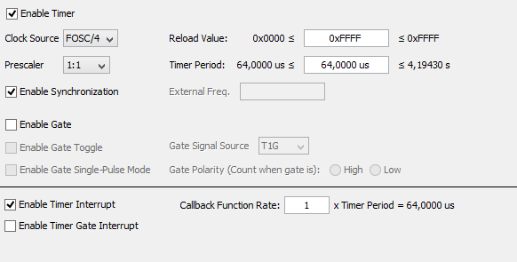
Here the main thing to pay attention to the inclusion of interrupts and call every interrupt function (the bottom line).
Now in the tmr1.c file at the very end there is a function that will be called every 64 microseconds (by the way, thanks to the wide capabilities (pay attention to the Reload Value field) we can change this value to “every 4 seconds”).
Since we love extensible and configurable code, we add two files to the project that are responsible for the operation of LEDs.
led.h:
Then in the led.c add "work" with color
And in the interrupt handler code
Finally, there is nothing left to do, how to write a verification code.
Compile, run and get a complete bummer. Nothing blinks and does not overflow. Why? I will spare you from thinking and searching. Because we set to generate an interrupt every 64 microseconds. And the processor clock speed was set at 62 kilohertz. That is, 1 clock cycle takes 16 microseconds. Does anyone believe that the processor is capable of performing all the jumble of commands, drawn above, in 4 cycles? So I do not believe. As a result, the microcontroller permanently hangs in the timer interrupt handler.
By logical reflections (in fact, a banal selection) we find out that one interrupt is processed in the order of 3 milliseconds (or FFC0 in the timer counter).
What is visible? Seen color changing LEDs that flicker. And "pure white" is not visible. What is the reason? The reason is in time, or rather in frequency. How do LEDs work for us now? 3ms on fire - 9ms not on fire. PWM frequency of 80 hertz with a filling of 25%. By experience, I know that the eye ceases to notice shim somewhere from 200 hertz.
What to do? The easiest way out is to raise the frequency. Sooner or later the eye will cease to notice flicker. Whatever frequency of sound we have “floated away”, we look at the possible values of the prescaler for TIM2 - 1: 1, 1: 4, 1:16 and 1:64. We now have a frequency of 62KHz, which means we can supply 62 * 4 = 250KHz, 62 * 16 = 1MHz or 62 * 64 = 4MHz.
The best is the enemy of the good, so I set the frequency of the microcontroller at 1 MHz, change the divider at 1:16 and re-fill the firmware. Hooray! Flicker disappeared.
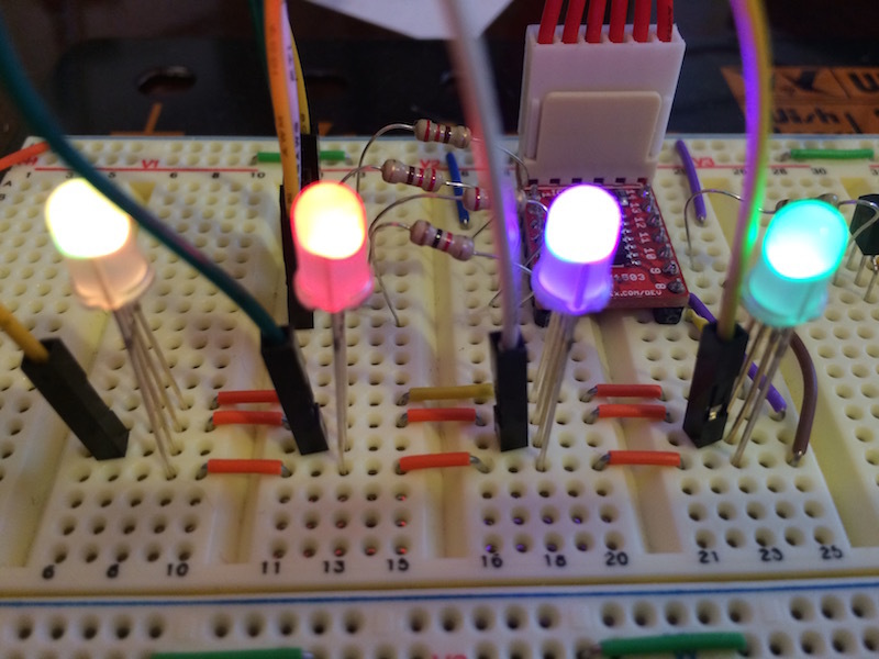
True, some colors ... not very. No, these are not iPhone glitches with which I took a photo. It really is only red like red (in fact there should be white-red-blue-green). And the switching is kind of sluggish, completely different from the required 50ms.
What is the problem? Again, the physicist's villain has tripped us up: in 180 microseconds (3ms / 16) the LED does not have time to “light up”. The result is what is visible in the photo.
What can be done? Well, again, this suggests a solution “on the forehead” - poking delays after ignition of the LED, so that it would catch fire. In principle, the solution is good. But it is better to first give a programmer on the head.
What for? Let's do a mental experiment and add 2 more LEDs. If we used to have PWM with a filling of 25%, now it will be at 16%. Adding four more will reduce to 10%. This is how it will be necessary to turn up the frequency and how to make sex with delays, so that the resulting construction would work?
Therefore, once again look at the algorithm. He now looks like this
- turn on the current LED and turn off the rest
- does the current led have something in the red channel? if yes, then turn on the red channel, otherwise turn off
- does the current led have something in the green channel? if yes, then turn on the green channel, otherwise turn off
- does the current led have something in the blue channel? if yes, then turn on the blue channel, otherwise turn off
And now we are going to cram more delays for each LED ... again we get flicker, again the frequency is raised. Full professional incompetence and sobbing in a dark corner are waiting for us if we don’t think of a way out :)
Since I do not want to cry, I change the algorithm for the next
- Turn on channel N (red, green, blue)
- Should the current channel H be lit in the LED M (0,1,2,3, ...)? If yes, then turn it on. If not, turn it off.
- Repeat the cycle for M
- We'll wait for the last LED to turn on.
- Repeat the cycle for H
It seems the difference is not big, but feel the difference: with any number of PWM LEDs for them will be with a filling of 33%. We are checking.
Code for one channel (the rest is completely similar). Definitions can also be viewed in the full version, but I think the names will be clear.
And we admire.
It is not so clearly seen in the photograph, but in reality green turned green and blue turned blue.
Well now we change to "almost like in the final."
Chandelier winks! Headlight shines! And the bottom is all green! In general, complete and unconditional success in our endeavors. We are cool! What else is needed for motivation? :) Get a little silence :) A preliminary demonstration of the results to the customer received full approval and allocation of additional amounts of resources for work (“Dad, I will behave very quietly for two evenings” and other parent blackmail)
Bonus for this business: almost NYPD blinking standard
The most thoughtful question for fights is: why does __delay_ms (_X_) in this case pause 5 times more than _X_ ms?
But that's not all. Next, consider the most important question: how to turn off this thing?
As usual, the complete set of everything lies here multik.org/pic/policelight.rar
I left the last post unfinished. If you remember, I couldn’t manage to find “that sound”. Attempts to pick up “tsiferki on a whim” turned out to be much worse than the usual “pi-piu” ... On the one hand all the same - from the Chinese tweeter no sound is achieved, but on the other hand - “unclean work, low class. Again, drive the clock frequency at 16 MHz for the sake of this ...
')
In general, I did something wrong somewhere. The next evening, an educational program on music and its literacy gave rise to even more questions than it was before (like why there is C sharp, but there is no re-sharp, but instead E-flat instead?). But I’m no stranger to "taking the Japanese by the manual", so I continued to understand. Simultaneously with the customer they discussed the change of the TZ (a familiar picture, isn’t it?), Which consisted in adding a “bottom light”. To my timid attempts to say that this is actually a police car, an answer was received that it was a police car in the Negro quarter ...
First I decided to finish the sound. I changed the frequencies and PWM, set the divider by 1 to 255, got the frequencies 7692 Hz and 62 Hz. The range has changed a bit, but still - quite.
And then something pulled me to measure the frequency with a divider 128. I expected to get something like (7692-62) / 2 = 3815 Hz, but for some reason I received only 125 ... And then me, as my favorite programmers in sweaters with deer , it dawned on: who said that the frequency-divider dependence is linear? A couple of extra measurements showed that I am absolutely right. A little bit of trachybidoc with an oscilloscope and an Excel feature gave just such a beautiful picture of Hz-Timer (originals as usual, in the archive at the end of the post):
Now it became clear to me why my sounds were so terrible. Plus, in the comments, they remembered the door bells, where in 2KB of ROM they thrust melodies ... When you know what to look for, it is found quickly.
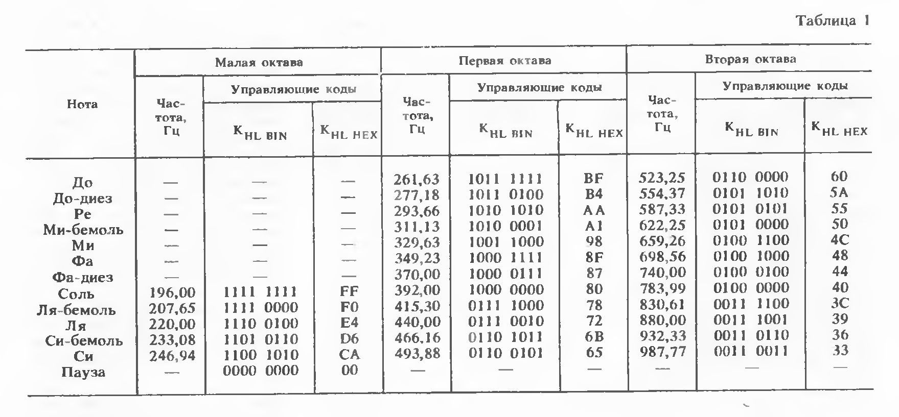
The first (like) such a scheme was published in the journal Radio, 92, 8th number. There was also a smart (for me) sign
And on the next page is the firmware itself. Even more googlezh and we find "Radio amateur", 93, February. There is absolutely the same principle, but there are more melodies.
Again, we charge the Excel (in the archive on the second tab) and transfer delays from “iron” to “soft”.
Add some code
// come cool sound const uint8_t m1[31]={49,49,52,52,58,58,58,58,38,38,28,52,52,52,52,52,52,52,52,38,38,36,38,36,38,52,52,49,49,49,49}; const uint8_t m2[31]={49,42,38,38,49,42,38,42,49,52,58,52,49,42,52,65,49,42,38,38,49,42,38,42,49,52,58,42,49,42,52}; // play like this uint8_t c; for(c=0;c<31;c++) { PWM3_LoadDutyValue(m1[c]*2); TMR2_LoadPeriodRegister(m1[c]); __delay_ms(120); } And cheers! From the Chinese tweeter heard quite a recognizable sound that does not offend even my ears. In principle, we can be proud of ourselves - we repeated the 20-year scheme on “logic” on a new element base. So even if the machine is not playable, you can always convert it into a doorbell :)
In general, while the process of finding the best “wah-wow” continues, but in principle we have closed the problem of sound. Go to the light.
As I wrote in the first post, the native LEDs were blue and very bright. Plus, I was outraged that blue shines through a red light filter and breaks all harmony. So you need to change.
He took out a red LED from the stash, turned it on. The first problem: the brightness is different. Blue is very bright. Changing to “from the stash” is still different. Of course, you can mute additional resistors, but it is too simple. Finally got to the RGB LED and the miracle happened! It shines with all colors with the same brightness. In principle, it is not surprising, because it costs as much as fifty "cheapest".
It was decided that I would take four RGB LEDs for all needs (the red and blue parts of the chandelier, the headlights and the bottom). My LEDs have a common cathode, so I will need 3 (RGB) * 4 (pieces) - 12 legs for control. Again, the problem: the microcontroller has only 12 (in general, 14, but two power) legs, one of which is allocated exclusively “to the input” (it hangs on the reset) and we have taken one to the “music”. And somewhere you need to hang the switch and leave the stock.
Usually in such cases it is easy to do: they take and install some kind of “port extender”. The most common option is a shift register type 74HC595. But putting a second microcircuit alongside is a brute force and a complete budget overrun. If all projects do this, then there will be nothing left for pies ... And we at studiovsemoe.com really love to eat :)
Therefore, I will go the other way and do everything with the controller. Spreading legs (all on the way out) like this

And I connect the LEDs like this (as usual, the complete diagram is in the archive)

In the diagram, I “broke” each LED into three separate ones, so that the operating principle would be clear. Well, for some reason, the resistors are plugged into 10k, although in reality they are 200-300 Ohm. As a result, we have a 4x3 LED matrix.
Attention: this scheme is suitable only for 1-2-3 LEDs. If you plan to connect more - use a special driver like L298 - otherwise the current through the output of the chip will be too large.
Add some code
LATCbits.LATC0 = 1; // RED LATCbits.LATC1 = 1; // GREEN LATCbits.LATC2 = 1; // BLUE LATCbits.LATC3 = 0; LATCbits.LATC4 = 0; LATCbits.LATC5 = 0; LATAbits.LATA5 = 0; Here we set the legs of C0-C2 in one, and C3-C5 and A5 - in zero. If everything is correctly assembled, then all the LEDs with a “white light” should light up.
What happened? As you know, the current flows from a place with a high potential to a place with a low one. And we have on some legs 1 (or + 3V), and on the other - 0. That LED lights up. If on those and on those legs apply 0 or 1 - nothing will burn. By the way, the universality of the circuit also emerges from here - if you do not have LEDs with a common cathode, like mine, but with a common anode, then in the code it will be enough for you to change 0 to 1 and everything will work.
As a result, combining the state of the C0-C2 legs, we can choose the color of the glow, while others choose which LED lights up from 4x, for the total, instead of the original 12 legs, it cost 7y. Not very cool (you can get by with 2 shift registers), but for our purposes it is more than enough.
But we have at least two LEDs to be on at the same time and in different colors (for example, a chandelier and a headlight, a headlight and a bottom). Here I use the old as the world trick: I will quickly switch between the LEDs and turn on the necessary colors. If done quickly enough, the eye will not notice flicker.
We try to blink colors (I think, the meaning can be understood from the notation)
LATCbits.LATC3 = 0; LATCbits.LATC4 = 0; LATCbits.LATC5 = 0; LATAbits.LATA5 = 0; while(1) { LATCbits.LATC0 = 1; LATCbits.LATC1 = 0; LATCbits.LATC2 = 0; __delay_ms(50); LATCbits.LATC0 = 0; LATCbits.LATC1 = 1; LATCbits.LATC2 = 0; __delay_ms(50); LATCbits.LATC0 = 0; LATCbits.LATC1 = 0; LATCbits.LATC2 = 1; __delay_ms(50); } And we look how beautifully the LEDs blink, turning over the colors ...
In principle, you can rewrite to work directly with the port - it's easier.
while(1) { LATC=0b00000001; __delay_ms(50); LATC=0b00000010; __delay_ms(50); LATC=0b00000100; __delay_ms(50); } What is the difference? The difference is. that the first option takes (with all the strapping) 89 bytes, and the second 81. 8 bytes of difference out of the blue. Well, the second is faster :)
If you do not understand, the design
LATC=0b00000001; Fully similar
LATCbits.LATC0 = 1; LATCbits.LATC1 = 0; LATCbits.LATC2 = 0; LATCbits.LATC3 = 0; LATCbits.LATC4 = 0; LATCbits.LATC5 = 0; LATCbits.LATC6 = 0; LATCbits.LATC7 = 0; Where are the cons? The downsides are that on some controllers, the high-order bits can be used for something useful, and we shove everything and use our dirty hands ...
Where else is the minus? Another disadvantage is that we again have to engage in "dragon race". Well, this is an unworthy business for talents like us. Don't bother doing this.
We have a timer that is responsible for the sound. No, we will not touch him, but we will touch his neighbors. For a change, take TIM1
How does it differ from TIM2? Firstly, greater accuracy - if TIM2 has a range divided into 255 parts, then here it is 65,535. So you can more accurately fall into the frequency. Secondly, he is not tied to anything and nothing is tied to him. And finally, its output can be brought to the foot of the microcontroller. Almost none of this is necessary for us, so we just allow it interrupts and we will blink LEDs in the interrupt handler.
In general, we set it up like this.

Here the main thing to pay attention to the inclusion of interrupts and call every interrupt function (the bottom line).
Now in the tmr1.c file at the very end there is a function that will be called every 64 microseconds (by the way, thanks to the wide capabilities (pay attention to the Reload Value field) we can change this value to “every 4 seconds”).
void TMR1_ISR(void) { // Clear the TMR1 interrupt flag PIR1bits.TMR1IF = 0; TMR1H = (timer1ReloadVal >> 8); TMR1L = timer1ReloadVal; // Add your TMR1 interrupt custom code } Since we love extensible and configurable code, we add two files to the project that are responsible for the operation of LEDs.
led.h:
// basic colors #define RED 1 #define GREEN 2 #define BLUE 4 #define OFF 0 // set led N to color C void setLed(uint8_t n,uint8_t c); // get color of led N uint8_t getLed(uint8_t n); extern volatile uint8_t lc[4]; // How LED connected #define _LED1_ LATCbits.LATC3 #define _LED2_ LATCbits.LATC4 #define _LED3_ LATCbits.LATC5 #define _LED4_ LATAbits.LATA5 #define _LEDR_ LATCbits.LATC0 #define _LEDG_ LATCbits.LATC1 #define _LEDB_ LATCbits.LATC2 Then in the led.c add "work" with color
volatile uint8_t lc[4]; // current led colors 0 - off void setLed(uint8_t n,uint8_t c) { lc[n]=c; } uint8_t getLed(uint8_t n) { return lc[n]; } And in the interrupt handler code
switch(current_led) { case 0: _LED1_=0; _LED2_=1; _LED3_=1; _LED4_=1; break; case 1: _LED1_=1; _LED2_=0; _LED3_=1; _LED4_=1; break; case 2: _LED1_=1; _LED2_=1; _LED3_=0; _LED4_=1; break; case 3: _LED1_=1; _LED2_=1; _LED3_=1; _LED4_=0; break; } if((lc[current_led]&RED)==RED) _LEDR_=1; else _LEDR_=0; if((lc[current_led]&GREEN)==GREEN) _LEDG_=1; else _LEDG_=0; if((lc[current_led]&BLUE)==BLUE) _LEDB_=1; else _LEDB_=0; current_led++; if(current_led>3) current_led=0; Finally, there is nothing left to do, how to write a verification code.
setLed(0,RED); setLed(1,GREEN); setLed(2,BLUE); setLed(3,RED+GREEN+BLUE); __delay_ms(50); setLed(1,RED); setLed(2,GREEN); setLed(3,BLUE); setLed(0,RED+GREEN+BLUE); __delay_ms(50); setLed(2,RED); setLed(3,GREEN); setLed(0,BLUE); setLed(1,RED+GREEN+BLUE); __delay_ms(50); setLed(3,RED); setLed(0,GREEN); setLed(1,BLUE); setLed(2,RED+GREEN+BLUE); __delay_ms(50); Compile, run and get a complete bummer. Nothing blinks and does not overflow. Why? I will spare you from thinking and searching. Because we set to generate an interrupt every 64 microseconds. And the processor clock speed was set at 62 kilohertz. That is, 1 clock cycle takes 16 microseconds. Does anyone believe that the processor is capable of performing all the jumble of commands, drawn above, in 4 cycles? So I do not believe. As a result, the microcontroller permanently hangs in the timer interrupt handler.
By logical reflections (in fact, a banal selection) we find out that one interrupt is processed in the order of 3 milliseconds (or FFC0 in the timer counter).
What is visible? Seen color changing LEDs that flicker. And "pure white" is not visible. What is the reason? The reason is in time, or rather in frequency. How do LEDs work for us now? 3ms on fire - 9ms not on fire. PWM frequency of 80 hertz with a filling of 25%. By experience, I know that the eye ceases to notice shim somewhere from 200 hertz.
What to do? The easiest way out is to raise the frequency. Sooner or later the eye will cease to notice flicker. Whatever frequency of sound we have “floated away”, we look at the possible values of the prescaler for TIM2 - 1: 1, 1: 4, 1:16 and 1:64. We now have a frequency of 62KHz, which means we can supply 62 * 4 = 250KHz, 62 * 16 = 1MHz or 62 * 64 = 4MHz.
The best is the enemy of the good, so I set the frequency of the microcontroller at 1 MHz, change the divider at 1:16 and re-fill the firmware. Hooray! Flicker disappeared.

True, some colors ... not very. No, these are not iPhone glitches with which I took a photo. It really is only red like red (in fact there should be white-red-blue-green). And the switching is kind of sluggish, completely different from the required 50ms.
What is the problem? Again, the physicist's villain has tripped us up: in 180 microseconds (3ms / 16) the LED does not have time to “light up”. The result is what is visible in the photo.
What can be done? Well, again, this suggests a solution “on the forehead” - poking delays after ignition of the LED, so that it would catch fire. In principle, the solution is good. But it is better to first give a programmer on the head.
What for? Let's do a mental experiment and add 2 more LEDs. If we used to have PWM with a filling of 25%, now it will be at 16%. Adding four more will reduce to 10%. This is how it will be necessary to turn up the frequency and how to make sex with delays, so that the resulting construction would work?
Therefore, once again look at the algorithm. He now looks like this
- turn on the current LED and turn off the rest
- does the current led have something in the red channel? if yes, then turn on the red channel, otherwise turn off
- does the current led have something in the green channel? if yes, then turn on the green channel, otherwise turn off
- does the current led have something in the blue channel? if yes, then turn on the blue channel, otherwise turn off
And now we are going to cram more delays for each LED ... again we get flicker, again the frequency is raised. Full professional incompetence and sobbing in a dark corner are waiting for us if we don’t think of a way out :)
Since I do not want to cry, I change the algorithm for the next
- Turn on channel N (red, green, blue)
- Should the current channel H be lit in the LED M (0,1,2,3, ...)? If yes, then turn it on. If not, turn it off.
- Repeat the cycle for M
- We'll wait for the last LED to turn on.
- Repeat the cycle for H
It seems the difference is not big, but feel the difference: with any number of PWM LEDs for them will be with a filling of 33%. We are checking.
Code for one channel (the rest is completely similar). Definitions can also be viewed in the full version, but I think the names will be clear.
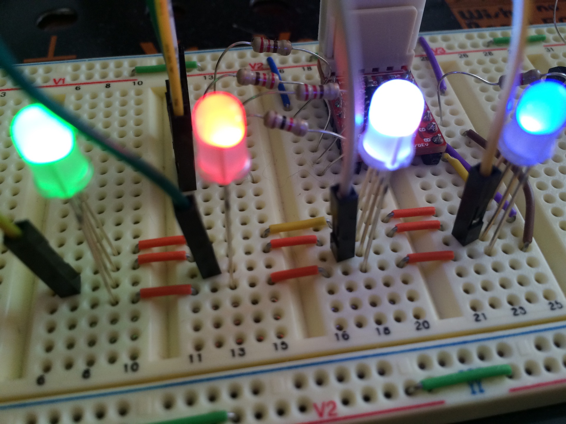
_LEDR_=_LEDON_; if ((lc[0] & RED) == RED) _LED1_ = _LEDOFF_; // INVERTED! else _LED1_ = _LEDON_; if ((lc[1] & RED) == RED) _LED2_ = _LEDOFF_; // INVERTED! else _LED2_ = _LEDON_; if ((lc[2] & RED) == RED) _LED3_ = _LEDOFF_; // INVERTED! else _LED3_ = _LEDON_; if ((lc[3] & RED) == RED) _LED4_ = _LEDOFF_; // INVERTED! else _LED4_ = _LEDON_; for(leds=0;leds<80;leds++) current_led++; _LEDR_=_LEDOFF_; And we admire.

It is not so clearly seen in the photograph, but in reality green turned green and blue turned blue.
Well now we change to "almost like in the final."
setLed(3,RED+GREEN+BLUE); setLed(2,GREEN); setLed(0,RED); __delay_ms(100); setLed(0,OFF); setLed(1,BLUE); __delay_ms(100); setLed(1,OFF); Chandelier winks! Headlight shines! And the bottom is all green! In general, complete and unconditional success in our endeavors. We are cool! What else is needed for motivation? :) Get a little silence :) A preliminary demonstration of the results to the customer received full approval and allocation of additional amounts of resources for work (“Dad, I will behave very quietly for two evenings” and other parent blackmail)
Bonus for this business: almost NYPD blinking standard
uint8_t c; setLed(3, RED + GREEN + BLUE); setLed(2, GREEN); while (1) { setLed(0, RED); setLed(1, OFF); __delay_ms(40); for (c = 0; c < 10; c++) { setLed(0, OFF); __delay_ms(10); setLed(0, RED); __delay_ms(10); } setLed(1, BLUE); setLed(0, OFF); __delay_ms(40); for (c = 0; c < 10; c++) { setLed(1, OFF); __delay_ms(10); setLed(1, BLUE); __delay_ms(10); } } The most thoughtful question for fights is: why does __delay_ms (_X_) in this case pause 5 times more than _X_ ms?
But that's not all. Next, consider the most important question: how to turn off this thing?
As usual, the complete set of everything lies here multik.org/pic/policelight.rar
Source: https://habr.com/ru/post/250229/
All Articles