Restoring hours "Electronics 7"
The other day, one friend brought me a watch on the vacuum-luminescent paws of the IV-26 “Electronics 7-06M”, or rather, what was left of them. This rather rare watch model is a small copy of the “Electronics 7-06K” watch. It’s not strange, but all the segments worked fine, only there were no boards with logic.
In some places, this post is more likely a manual “how not to do”. Definitely it is better not to use a mounted installation, test the design on the debug board, and then, having etched the board with LUT, using the penny atmega8 for example, unsolder the circuit nicely and accurately.
And so, I had a free evening, a persistent desire to bring this watch to life, and the complete absence of prototyping boards and foil textolite. On the board under the indicators, a cascade of keys consisting of KT209 and limiting the current on the base of 15 kΩ resistors was soldered.

')
The indicators themselves are already connected into assemblies of 4 pieces with 7 segments, it remains only to separate the second cascade of anode keys for each assembly segment, and isolating the common power supply at the anode of each of the four indicator assemblies, hang the keys to control the power of the assembly.

To begin with, we solder a train of 7 cores, connecting all four assemblies of the segments in parallel, and with a 4 core cable we draw power to the anodes of each assembly.

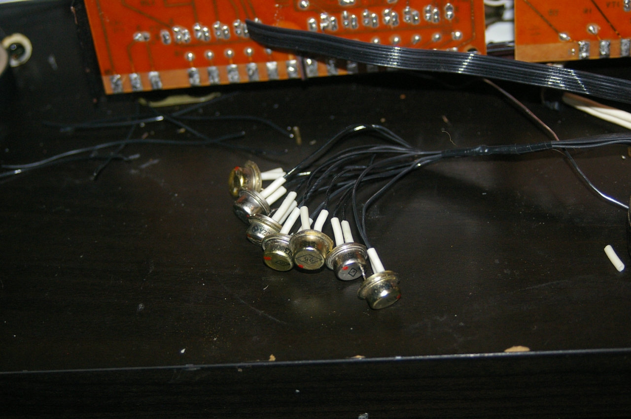
Further, having rummaged in the bins depleted after the move, it was found:
Resistors for 10kOhm and 2.2kOhm, charging from "Nokia", a scattering of transistors "2t602a" and five pieces "KT315A". Not thick, but enough.
First of all, we hang up the second cascade of keys along the anodes of individual segments - there are seven of them.
On the base we limit the current by resistors to 10kΩ.
Then we make the control of switching on the assemblies using “KT315A”, connect them to the ground through 2.2kOhm resistors, through the same 2.2kOhm we connect the leads from the anodes, we restrict the base current to 10kOhms again. Super glue will save the planet, I'm sure of it.
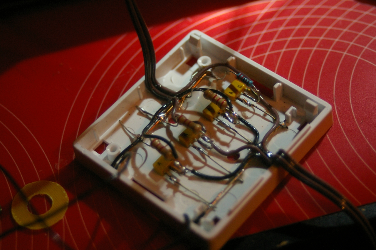
As a result, while on base 0, the assembly is on, filed +5, the assembly has gone out, and individual segments are controlled per turn: +5 served, the segment is on, 0 is on the segment. It's as simple as a cucumber.
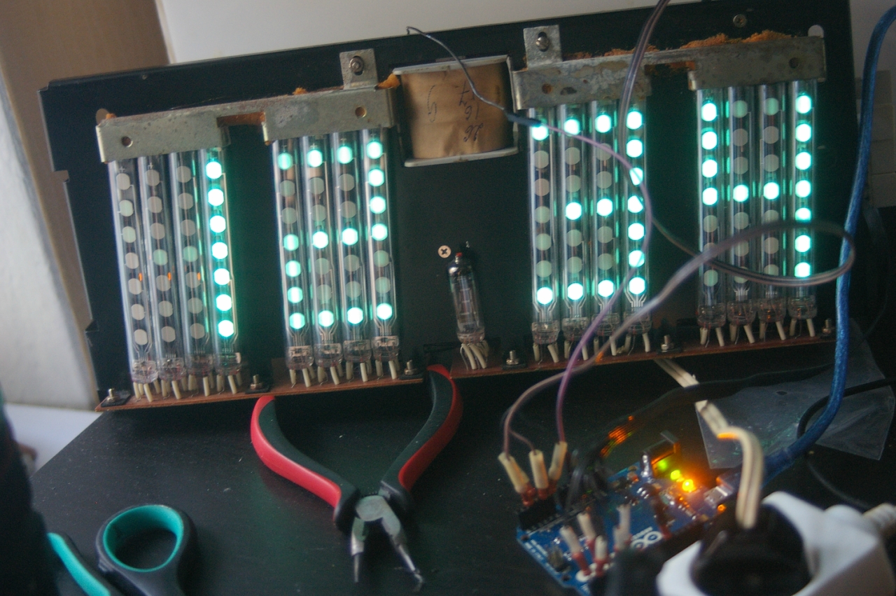
The principle of operation of the whole structure - we light every assembly for a couple of milliseconds, at the same time applying voltage to the segments we need, we in turn light up different assemblies of segments and each one has its own figure.
To manage all this splendor, a long-unused copy of the arduino leonardo with a burned high “portc” and some strange glitches was used, consisting in the fact that sometimes it is not possible to flash it without forcing a reboot. It used to be used to quickly check all sorts of things, and since I never had enough care, I partially died the death of the brave, under not quite clarified circumstances, working as a breaker for DRSSTC. I got it in my time “for free”, a fan of this platform, and even more so of this board (ardent greetings to the developers for a very convenient port mapping for example) was not, so “Trofim died - and to hell with it!”.
But there are enough live ports for this purpose, and since there was no decoder, we use the whole portD for character generation, which, although in inconsistency, is still present almost entirely on the block, with the exception of the pin "5". To enable or disable assemblies of segments, use the “A0-A3” pins on the board. "A4" will receive testimony from a thermocouple. Also for the four buttons we use the pins “7-10” on the board: 9 and 8 - setting the hours and minutes, 7 - stopping the clock, 10 - switching the temperature display \ hours.
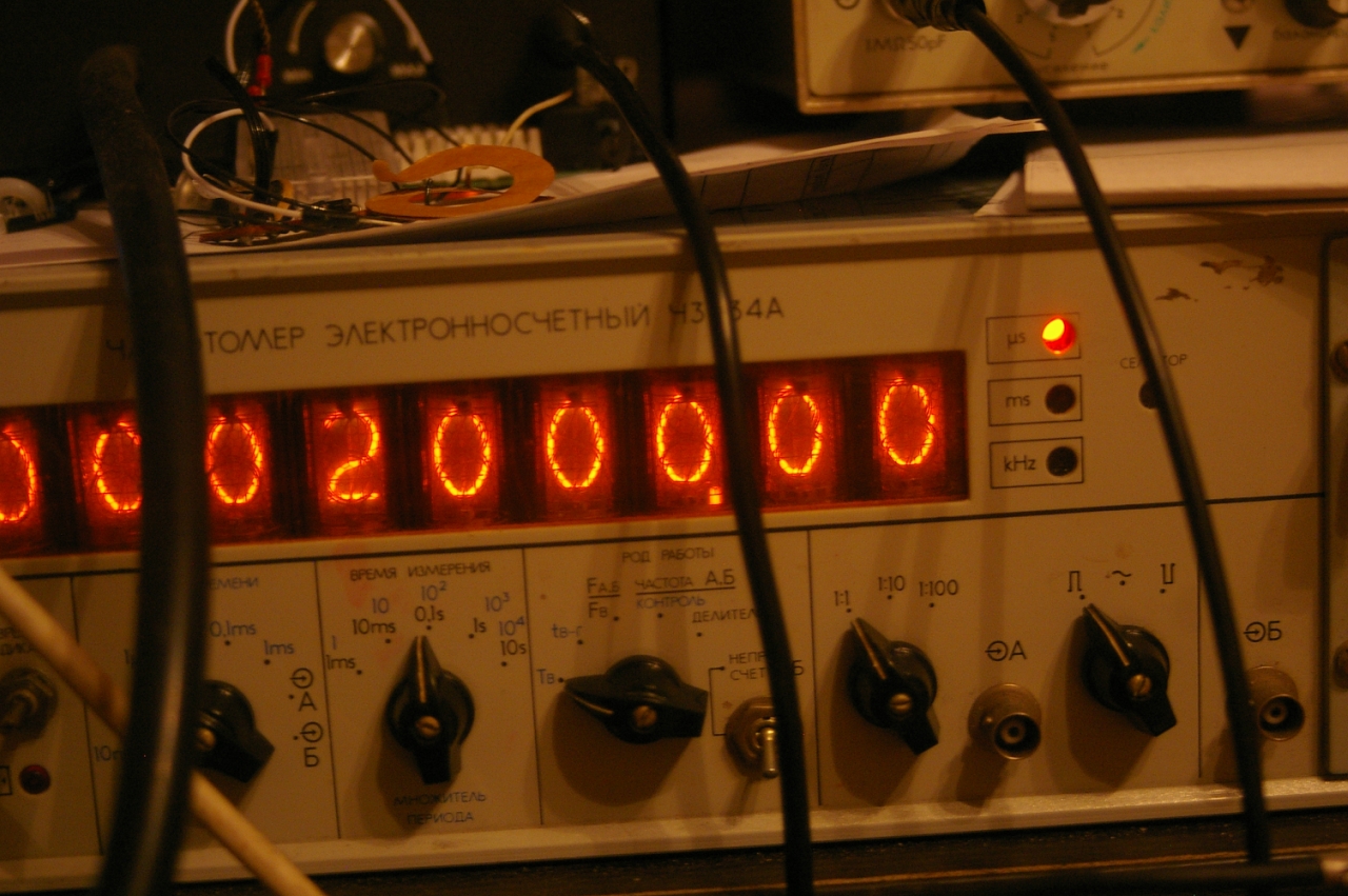
After a couple of hours, the firmware was wrap and it worked! It remains only to check the accuracy of the course. For this you need a frequency meter with the function of measuring the duration of the period. Every two milliseconds we send a test signal, while seeing how far the duration of the period corresponds to 2 milliseconds real. If necessary, enter the correction factor.
After that, a thermistor was added, buttons were connected, and the accuracy of the stroke was again checked.
As a power source for arduina, the old charging from "nokia" appeared.

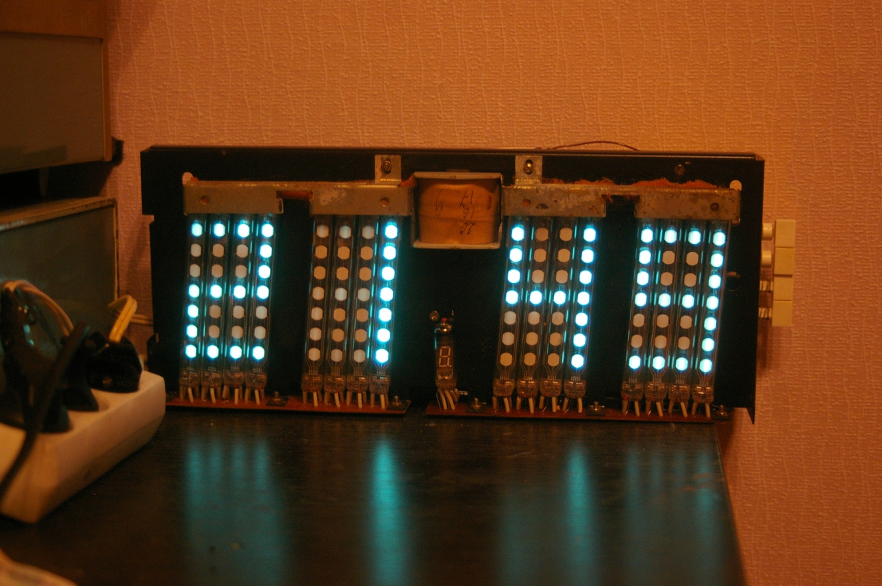
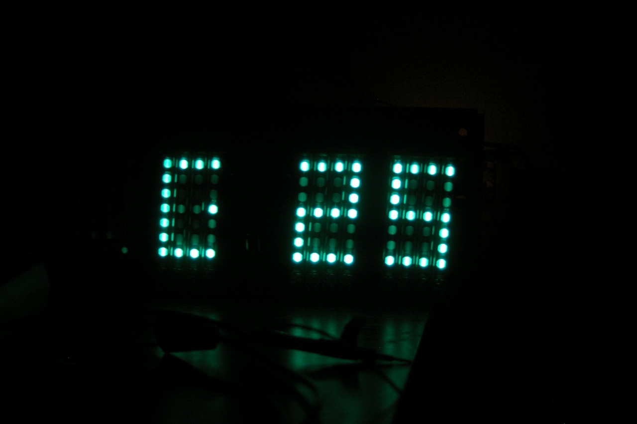
The finished device can display the time:

And temperature:
Of the minuses - about half the brightness, as compared with the factory product (which is logical - the static display is used in the original, but not dynamic).
Original circuits "Electronics 7-06M": yadi.sk/d/Ebli4xXmeWnyi
Leonardo firmware code: pastebin.com/i8bsZWhU (for processing the data from the thermocouple, the friend's code hookenful was used, for which many thanks to him).
Source: https://habr.com/ru/post/249971/
All Articles