How to recover incorrectly exposed fyuzy in ATtiny

Hello to all habrauser. I think many people involved in microcontrollers have little experience in “blocking” the microcontroller with incorrectly set fusion bits, for example, incorrect clocking settings, in particular, a very low frequency, for example, 16 kHz.
Also, this method should be suitable for cases when there were randomly changed RSTDISBL fusion bits, and more specifically, the RESET port is used as an input / output port or a careless attitude to the SPIEN fusion bit (permission for sequential programming), this excludes classic firmware using the SPI (In-System Programming) protocol.
')
In this video I will tell, and show you how you can unlock microcontrollers from the ATtiny series that have not properly exposed fusion bits.
This method is not suitable for all ATtiny, but is suitable for most popular ones, here is a list of them:
- ATtiny13;
- ATtiny24;
- ATtiny25;
- ATtiny44;
- ATtiny45;
- ATtiny84;
- ATtiny85.
In the video, I showed how to restore factory fusion beats using Arduino, in fact, the information presented below is duplicated in video format.
I will say right away that the project of Comrade Wayne Holder was taken as a basis, for which I thank him very much, here is a link to his article .
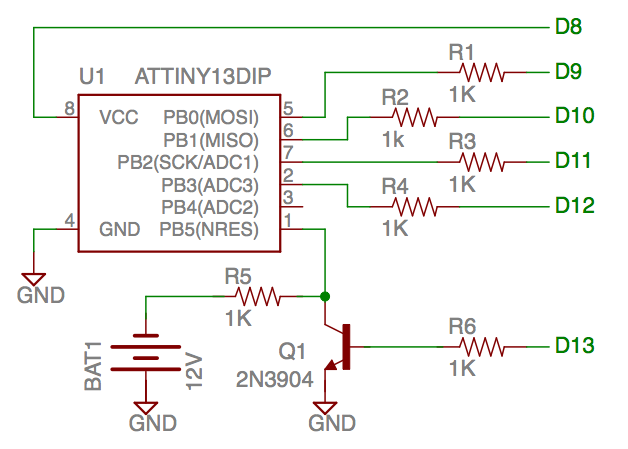
So let's get started, here is the wiring diagram using the example of ATtiny13:
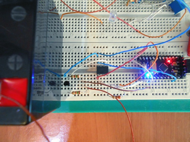
And this is how this scheme looks like in my performance:
Pro connection to ATtiny25 / 45/85/24/44/84 will be lower.
As you can see, the circuit consists of 6 resistors of 1 KΩ, 1 NPN transistor 2n3904, here is its pinout:
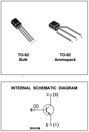
You can take the Soviet KT315 , or its analogues, well, the actual voltage source is 11.5-12.5 V, as recommended by ATmel engineers in the documentation for those microcontrollers mentioned above. I don’t think that it’s worth overstating or understating the voltage, so before the restoration I advise you to check the voltage on the power source with a voltmeter or multimeter. At the time of shooting the video, the voltage on my battery was 12.4 V.
A few words where you can take 12 V - this is all sorts of power supplies for routers or modems, for example, my DSL modem ASUS DSL-N10E just has a 12 V power supply, as a rule, voltage is indicated on each power supply.
Also, 12 V can be taken from the computer MOLEX connector :

And more precisely - yellow and black.
It is worth mentioning that you need to be careful when connecting the 12 V part , because this voltage easily burns both microcontrollers and other Arduino peripherals, such as a USB-TTL converter, refer to personal experience. Therefore, we follow the algorithm:
- We collect the scheme;
- We supply power to the Arduino by connecting to usb;
- Serves + 12V to the transistor;
- We restore the microcontroller;
- Disable + 12V.
This is how I dumped ATtiny13 fusion bits (used the Reset port as an input / output port), already 10-15 times when debugging one of my projects, here is a short video preview of it:
LCD (HD44780) voltmeter on ATtiny13
We connect to our other microcontrollers our “rejuvenating fusion bits” as follows:

- The RST ATtiny port is connected between a resistor of 1 KΩ, the one that connects to + 12V, and the collector of the VT1 transistor;
- The 13th pin of the Arduino, also known as PB5, is connected via a 1 KΩ resistor to the base of the VT1 transistor;
- The 12th pin of the Arduino, also known as PB4, is connected via a 1 KΩ resistor to the SCI (Target Clock Input) ATtiny;
- The 11th pin of the Arduino, also known as PB3, is connected via a 1-kΩ resistor to the SDO (Target Data Output) ATtiny;
- The 10th pin of the Arduino, also known as PB2, is connected via a resistor of 1 kΩ to the SII (Target Instruction Input) ATtiny;
- The 9th pin of the Arduino, also known as PB1, is connected via a 1 KΩ resistor to the SDI (Target Data Input) ATtiny;
- The 8th pin of the Arduino, also known as PB0, is preferably connected via a 100-330 ohm resistor to the VCC ATtiny, just in case.
- GND - of course common wire or in other words "earth".
All this is reassigned in the code, no problem.
Here is the code from the author's page
// AVR High-voltage Serial Fuse Reprogrammer // Adapted from code and design by Paul Willoughby 03/20/2010 // http://www.rickety.us/2010/03/arduino-avr-high-voltage-serial-programmer/ // // Fuse Calc: // http://www.engbedded.com/fusecalc/ #define RST 13 // Output to level shifter for !RESET from transistor #define SCI 12 // Target Clock Input #define SDO 11 // Target Data Output #define SII 10 // Target Instruction Input #define SDI 9 // Target Data Input #define VCC 8 // Target VCC #define HFUSE 0x747C #define LFUSE 0x646C #define EFUSE 0x666E // Define ATTiny series signatures #define ATTINY13 0x9007 // L: 0x6A, H: 0xFF 8 pin #define ATTINY24 0x910B // L: 0x62, H: 0xDF, E: 0xFF 14 pin #define ATTINY25 0x9108 // L: 0x62, H: 0xDF, E: 0xFF 8 pin #define ATTINY44 0x9207 // L: 0x62, H: 0xDF, E: 0xFFF 14 pin #define ATTINY45 0x9206 // L: 0x62, H: 0xDF, E: 0xFF 8 pin #define ATTINY84 0x930C // L: 0x62, H: 0xDF, E: 0xFFF 14 pin #define ATTINY85 0x930B // L: 0x62, H: 0xDF, E: 0xFF 8 pin void setup() { pinMode(VCC, OUTPUT); pinMode(RST, OUTPUT); pinMode(SDI, OUTPUT); pinMode(SII, OUTPUT); pinMode(SCI, OUTPUT); pinMode(SDO, OUTPUT); // Configured as input when in programming mode digitalWrite(RST, HIGH); // Level shifter is inverting, this shuts off 12V Serial.begin(19200); } void loop() { if (Serial.available() > 0) { Serial.read(); pinMode(SDO, OUTPUT); // Set SDO to output digitalWrite(SDI, LOW); digitalWrite(SII, LOW); digitalWrite(SDO, LOW); digitalWrite(RST, HIGH); // 12v Off digitalWrite(VCC, HIGH); // Vcc On delayMicroseconds(20); digitalWrite(RST, LOW); // 12v On delayMicroseconds(10); pinMode(SDO, INPUT); // Set SDO to input delayMicroseconds(300); unsigned int sig = readSignature(); Serial.print("Signature is: "); Serial.println(sig, HEX); readFuses(); if (sig == ATTINY13) { writeFuse(LFUSE, 0x6A); writeFuse(HFUSE, 0xFF); } else if (sig == ATTINY24 || sig == ATTINY44 || sig == ATTINY84 || sig == ATTINY25 || sig == ATTINY45 || sig == ATTINY85) { writeFuse(LFUSE, 0x62); writeFuse(HFUSE, 0xDF); writeFuse(EFUSE, 0xFF); } readFuses(); digitalWrite(SCI, LOW); digitalWrite(VCC, LOW); // Vcc Off digitalWrite(RST, HIGH); // 12v Off } } byte shiftOut (byte val1, byte val2) { int inBits = 0; //Wait until SDO goes high while (!digitalRead(SDO)) ; unsigned int dout = (unsigned int) val1 << 2; unsigned int iout = (unsigned int) val2 << 2; for (int ii = 10; ii >= 0; ii--) { digitalWrite(SDI, !!(dout & (1 << ii))); digitalWrite(SII, !!(iout & (1 << ii))); inBits <<= 1; inBits |= digitalRead(SDO); digitalWrite(SCI, HIGH); digitalWrite(SCI, LOW); } return inBits >> 2; } void writeFuse (unsigned int fuse, byte val) { shiftOut(0x40, 0x4C); shiftOut( val, 0x2C); shiftOut(0x00, (byte) (fuse >> 8)); shiftOut(0x00, (byte) fuse); } void readFuses () { byte val; shiftOut(0x04, 0x4C); // LFuse shiftOut(0x00, 0x68); val = shiftOut(0x00, 0x6C); Serial.print("LFuse: "); Serial.print(val, HEX); shiftOut(0x04, 0x4C); // HFuse shiftOut(0x00, 0x7A); val = shiftOut(0x00, 0x7E); Serial.print(", HFuse: "); Serial.print(val, HEX); shiftOut(0x04, 0x4C); // EFuse shiftOut(0x00, 0x6A); val = shiftOut(0x00, 0x6E); Serial.print(", EFuse: "); Serial.println(val, HEX); } unsigned int readSignature () { unsigned int sig = 0; byte val; for (int ii = 1; ii < 3; ii++) { shiftOut(0x08, 0x4C); shiftOut( ii, 0x0C); shiftOut(0x00, 0x68); val = shiftOut(0x00, 0x6C); sig = (sig << 8) + val; } return sig; } As you can see, nothing intricate, sent any character to Arduino via UART and voila, the fusion bits are restored to the factory ones, while we also see which ones were before unlocking and which became.
My previous article about how to turn an Arduino into a full-fledged AVRISP programmer . There you can read about the software mentioned in the video firmware microcontroller.
I also recommend visiting a slightly different project of Comrade Wayne Holder :
ATTiny Fuse Reset with 12 Volt Charge Pump
The essence is the same, just do not need to look for a source of 12 V.
All my publications .
PS Serial.begin (19200);
Source: https://habr.com/ru/post/249967/
All Articles