Model of access control systems in an enterprise based on Arduino
On forums, people periodically appear willing to make their own ACS for a car or office from the arduino starter kit. On the convergence of stars and with the support of inspiration drawn from the news about the Free and open-source software (FOSS), this is what we decided to do in our spare time. The description of the intermediate result of the work was submitted to submit an application for publication in an almost well-known journal . Surrounding the waters and brief definitions of the component parts, it contains a description of everything necessary for writing, successfully compiling and flashing the sketch that controls the model. The stated goal of the work is to create an analogue of what can now be found on this topic in a market that would be competitive due to low prices.
Access Control Systems (ACS) is an effective access control system that allows you to manage the security of an object and control access. The aim of the work is to demonstrate the possibility of implementing an ACS model based on a software-compatible analogue of arduino, which will be significantly more profitable in commercial terms as compared to existing industrial analogues.
Keywords. Security, engineering and technical information protection, information protection, safety devices and measures, territory control, wearable authorization devices, RFID, token, Arduino.
One of the areas of information security in an enterprise or organization is engineering and technical protection, within which access control and management systems are used.
')
A specialist designing an information protection system for an organization is often tasked with providing protection for employees in a certain area within which free exchange is possible. As an element of such a system, you can offer devices developed on the basis of Arduino boards.
The Radio Frequency IDentification (RFID) technology used to implement the system is a method of remotely storing and retrieving information by transmitting radio signals using devices called RFID tags [ 13.56 MHz technology , RFID operation principle ]. This technology is one of those whose elements are wearable by users of systems built on these technologies, special high-tech identifiers - tokens (English token).
The architectural type of label we used is “passive”. Passive RFID tags do not have an embedded power source. The chip, which provides the tag operation, is powered by an electrical current request signal induced in the antenna.
Table 1
Passive RFID tags
Below is an example of the distribution of the characteristics of RFID tags over the working frequency ranges:
table 2
RFID classification by frequency range:
ACS based on RFID are installed everywhere where it is advisable to install it. These are territories, access to which must be granted to a strictly limited circle of persons. In addition, RFID used in the manufacture of European and American passports, various credit cards; in animal husbandry, car security systems.
The following describes the scenario of interaction with the system (Fig. 1). An employee of the company or an alleged attacker, passing into a controlled area, provides its RFID tag. The system module responsible for obtaining information from the RFID tag must read and analyze the data obtained using the system database containing the correspondences between the records on the tags and the employees who own the tags. If the provided label is registered in the database, then the system should skip the employee. Otherwise, it is optional to signal the failure of authorization.

Fig. 1. Modular chart.
The arrows indicate the ways of information exchange between the components.
The control device will be the Arduino board with the program recorded in its controller. Reading the information from the RFID tag will be done by the special RFID-RC522 circuit [ Mifare RC522 RFID Module ], and the signals about the system model will be sent using an LED and an elementary audio device (buzzer) [ Buzzer Arduino Example Code ]. The access control module will be executed by the SG90 servo motor [ SG 90 9g Micro Servo ].
The Arduino platform selected as the basis for developing the system is provided by the software [ Arduino code tutorials and examples ] developed for use with it.
Arduino IDE 1.0.6, a free-distributed integrated development environment, solves the problem of convenient writing, compiling, and loading control code.
The library <MFRC522.h> [ Arduino library for MFRC522 ] was used to work with the RFID-RC522 module. Using methods from the class MFRC522 declared in it is the ability to read information from RFID tags. In this case, we define “ours” with the help of only uid tags. These are four bytes, if they coincide with the recorded ones, a signal about successful authorization will be given and actions will be performed, symbolizing the granting of access.
To control the servomotor, we needed the <Servo.h> supplied with the IDE, containing, among others, the description of the Servo class. This class “connects” to the port specified by the number and allows using the methods attached (attach (int port) and write (int val)) to select the port to work with the servomotor and set the position of the servo rotor, respectively.
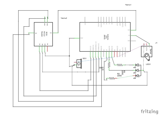
Fig. 2. Schematic diagram
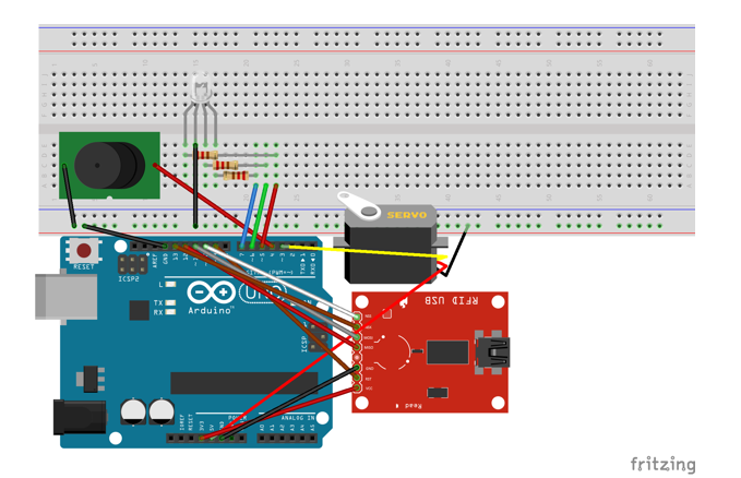
Fig. 3. The appearance of the result of the assembly Lessons Fritzing
Video demo:
Presentation
At the end of the design, assembly and testing process, you can summarize - calculate our non-model costs and compare them with those already on the market. Under the non-model costs we understand the modules that really ensure the proper operation of the system. In this case, the components we use will not be replaced, but the system requires an access control module. An example would be a magnetic lock.
The prices shown in the table were obtained in the process of analyzing the market for these components at the time of the work and were recognized as “moderate” by the authors.
Table 3
List of components and prices:
The result of our work was a model of access control, not claiming the status of a prototype of the finished commercial product. This software and hardware complex is not completed, which makes it difficult to estimate the resulting cost of our device. But already on the basis of the data we have, we can say that the material costs for the technical side of the implementation of this system (it is supposed to write a set of software solutions that provide management of it using a PC) are insignificant compared to existing industrial analogues. And the work, the application of which is necessary for the final realization of the entire access control system, is student’s, that is, free.
PS To further reduce the cost of access control, you can use touch memory instead of RFID and a cheaper analogue of Arduino (Nano).
Access Control Systems (ACS) is an effective access control system that allows you to manage the security of an object and control access. The aim of the work is to demonstrate the possibility of implementing an ACS model based on a software-compatible analogue of arduino, which will be significantly more profitable in commercial terms as compared to existing industrial analogues.
Keywords. Security, engineering and technical information protection, information protection, safety devices and measures, territory control, wearable authorization devices, RFID, token, Arduino.
One of the areas of information security in an enterprise or organization is engineering and technical protection, within which access control and management systems are used.
')
A specialist designing an information protection system for an organization is often tasked with providing protection for employees in a certain area within which free exchange is possible. As an element of such a system, you can offer devices developed on the basis of Arduino boards.
RFID
The Radio Frequency IDentification (RFID) technology used to implement the system is a method of remotely storing and retrieving information by transmitting radio signals using devices called RFID tags [ 13.56 MHz technology , RFID operation principle ]. This technology is one of those whose elements are wearable by users of systems built on these technologies, special high-tech identifiers - tokens (English token).
The architectural type of label we used is “passive”. Passive RFID tags do not have an embedded power source. The chip, which provides the tag operation, is powered by an electrical current request signal induced in the antenna.
Table 1
Passive RFID tags
| Functionality | Only read / read-write. |
| Frequency. | 125KHz / 13.56MHz / 915 MHz / 2.45GHz read-write. |
| Reading distance. | Up to 6 m + (with installed antenna). |
| Sizes. | Different, ~ 0.8 mm in diameter. |
| Weight. | 6 - 54 gr. |
| Memory. | Up to 16 Kbit. |
| Lifetime. | 10 years. |
| Temperature mode. | - 40 to + 70 Celsius. |
Below is an example of the distribution of the characteristics of RFID tags over the working frequency ranges:
table 2
RFID classification by frequency range:
| Characteristic | Low frequencies (LF, LF) - 125-134 kHz | High frequencies (HF, HF) - 13.56 MHz | Ultra-high frequencies (UHF, UHF) - 860-960 MHz | Microwave (SHF) - 2.4 GHz |
|---|---|---|---|---|
| Maximum reading distance | from 3 to 70 cm. | from 3 to 100 cm. | from 10 cm to 4 m. | 2-10 m. |
| Data transfer rate tag reader | about 9600 bps | up to 64 kbps | up to 128 kbps | up to 128 kbps |
| Presence of anticollision | There are, but not all chips. | There is. | There is. | There is. |
| RFID Memory Capacity | 32-1024 bytes. | 8-16384 bytes. | 64-1024 bits (ISO), 64 or 96 bits (EPC). | from 64 bits to 32 kbps. |
RFID Applications
ACS based on RFID are installed everywhere where it is advisable to install it. These are territories, access to which must be granted to a strictly limited circle of persons. In addition, RFID used in the manufacture of European and American passports, various credit cards; in animal husbandry, car security systems.
System user interface
The following describes the scenario of interaction with the system (Fig. 1). An employee of the company or an alleged attacker, passing into a controlled area, provides its RFID tag. The system module responsible for obtaining information from the RFID tag must read and analyze the data obtained using the system database containing the correspondences between the records on the tags and the employees who own the tags. If the provided label is registered in the database, then the system should skip the employee. Otherwise, it is optional to signal the failure of authorization.
Fig. 1. Modular chart.
The arrows indicate the ways of information exchange between the components.
Model development
The control device will be the Arduino board with the program recorded in its controller. Reading the information from the RFID tag will be done by the special RFID-RC522 circuit [ Mifare RC522 RFID Module ], and the signals about the system model will be sent using an LED and an elementary audio device (buzzer) [ Buzzer Arduino Example Code ]. The access control module will be executed by the SG90 servo motor [ SG 90 9g Micro Servo ].
Arduino
The Arduino platform selected as the basis for developing the system is provided by the software [ Arduino code tutorials and examples ] developed for use with it.
Arduino IDE 1.0.6, a free-distributed integrated development environment, solves the problem of convenient writing, compiling, and loading control code.
The library <MFRC522.h> [ Arduino library for MFRC522 ] was used to work with the RFID-RC522 module. Using methods from the class MFRC522 declared in it is the ability to read information from RFID tags. In this case, we define “ours” with the help of only uid tags. These are four bytes, if they coincide with the recorded ones, a signal about successful authorization will be given and actions will be performed, symbolizing the granting of access.
To control the servomotor, we needed the <Servo.h> supplied with the IDE, containing, among others, the description of the Servo class. This class “connects” to the port specified by the number and allows using the methods attached (attach (int port) and write (int val)) to select the port to work with the servomotor and set the position of the servo rotor, respectively.
Fig. 2. Schematic diagram
The program code of the controller
/* < Arduino. buzzer, RGBLED RFID-reader> Copyright (C) <2014> <Ilyin II Zubov YM> This program is free software; you can redistribute it and/or modify it under the terms of the GNU General Public License as published by the Free Software Foundation; either version 3 of the License, or (at your option) any later version. This program is distributed in the hope that it will be useful, but WITHOUT ANY WARRANTY; without even the implied warranty of MERCHANTABILITY or FITNESS FOR A PARTICULAR PURPOSE. See the GNU General Public License for more details. You should have received a copy of the GNU General Public License along with this program; if not, write to the Free Software Foundation, Inc., 51 Franklin Street, Fifth Floor, Boston, MA 02110-1301 USA */ #include <SPI.h> // Arduino IDE SPI . ? https://ru.wikipedia.org/wiki/Serial_Peripheral_Interface #include <Servo.h> // Arduino IDE #include <MFRC522.h> // -. ? https://github.com/miguelbalboa/rfid // - #define SS_PIN 10 #define RST_PIN 9 const int RGB_LED_PINUMBERS[] = { 5, 6, 7 }; // - RGB- const int SERVO_PINUMBER = 3; // const int BUZZER_PINUMBER = 4; // const int BUTTON_PINUMBER = 2; // , const int NEW_CARD_CHECK_DELAY = 500; // const int OPEN_CLOSE_DELAY = 3000; // const byte tehUID[4] = { 0x33, 0xFF, 0x6B, 0x9A }; // tehUID , bool buttonState = 0; // enum States { // : wait, check, open, close }; States state; // bool rightCard; // , bool white; // ( ), int pos = 0; // () Servo myservo; // Servo MFRC522 mfrc522(SS_PIN, RST_PIN); // MFRC522 -. void setup() { Serial.begin(9600); // SPI.begin(); // SPI-. mfrc522.PCD_Init(); // - myservo.attach(SERVO_PINUMBER); // Serial.println("Scan PICC to see UID and type..."); // , . white = false; // state = wait; // // RGB-: pinMode(RGB_LED_PINUMBERS[0], OUTPUT); // red pinMode(RGB_LED_PINUMBERS[1], OUTPUT); // green pinMode(RGB_LED_PINUMBERS[2], OUTPUT); // blue pinMode(BUZZER_PINUMBER, OUTPUT); // pinMode(BUTTON_PINUMBER, INPUT); // , } void loop() { switch (state){ case wait: Waiting(); return; case check: Checking(); return; case open: Opening(); return; case close: Closing(); return; } } void Waiting(){ delay(NEW_CARD_CHECK_DELAY); /// : if (!white){ digitalWrite(RGB_LED_PINUMBERS[0], HIGH); // digitalWrite(RGB_LED_PINUMBERS[1], HIGH); // digitalWrite(RGB_LED_PINUMBERS[2], HIGH); // white = true; } else{ digitalWrite(RGB_LED_PINUMBERS[0], LOW); // digitalWrite(RGB_LED_PINUMBERS[1], LOW); // digitalWrite(RGB_LED_PINUMBERS[2], LOW); // white = false; } // : if (mfrc522.PICC_IsNewCardPresent()) state = check; // buttonState = digitalRead(BUTTON_PINUMBER); // // , buttonState HIGH: if (buttonState == HIGH) { state = open; } } void Checking(){ // : digitalWrite(RGB_LED_PINUMBERS[0], HIGH); // digitalWrite(RGB_LED_PINUMBERS[1], HIGH); // digitalWrite(RGB_LED_PINUMBERS[2], LOW); // // UID if (!mfrc522.PICC_ReadCardSerial()) { return; } delay(500); rightCard = true; // // UID: for (byte i = 0; i < 4; i++) { if (tehUID[i] != mfrc522.uid.uidByte[i]) rightCard = false; } if (rightCard) state = open; // , else{ Serial.println("Unknown CARD."); digitalWrite(5, HIGH); // digitalWrite(6, LOW); // digitalWrite(7, LOW); // digitalWrite(4, HIGH); //buzz(4, 7000, 2000); // buzz the buzzer on pin 4 at 2500Hz for 500 milliseconds delay(2000); // wait a bit between buzzes digitalWrite(4, LOW); state = wait; // , } } void Opening(){ Serial.println("OPEN"); digitalWrite(RGB_LED_PINUMBERS[0], LOW); digitalWrite(RGB_LED_PINUMBERS[1], HIGH); // digitalWrite(RGB_LED_PINUMBERS[2], LOW); delay(500); // . . . ServoOpen(); state = close; } void Closing(){ delay(OPEN_CLOSE_DELAY); digitalWrite(RGB_LED_PINUMBERS[1], LOW); // ServoClose(); state = wait; } // 180: void ServoOpen(){ for (pos = 0; pos <= 180; pos += 1){ // myservo.write(pos); // delay(15); // 15 } } void ServoClose(){ for (pos = 180; pos >= 0; pos -= 1){ myservo.write(pos); delay(15); } } /* , , , 2014. GPLv3. . : http://www.gnu.org/licenses/gpl-3.0.html */ Fig. 3. The appearance of the result of the assembly Lessons Fritzing
Video demo:
Presentation
Summarizing
At the end of the design, assembly and testing process, you can summarize - calculate our non-model costs and compare them with those already on the market. Under the non-model costs we understand the modules that really ensure the proper operation of the system. In this case, the components we use will not be replaced, but the system requires an access control module. An example would be a magnetic lock.
The prices shown in the table were obtained in the process of analyzing the market for these components at the time of the work and were recognized as “moderate” by the authors.
Table 3
List of components and prices:
| Designation | Qty | Type of | Properties | Cost of |
|---|---|---|---|---|
| LED1 | one | RGB LED | 4-pin RGB LED with common anode | 10-20 p / pcs |
| R1, R2, R3 | 3 | 220Ω resistor | tolerance ± 5% resistance 220Ω | 30p / 50pcs |
| SG1 | one | Buzzer 12mm | Buzzer 12mm | 5p / pc |
| Part 1 | one | Arduino Uno (Rev3) | microcontroller based on ATmega328 | 300-400r / pcs |
| Part 2 | one | RFID-RC522 | RFID card read / write module at a frequency of 13.56 MHz | 250-350r / pcs |
Conclusion
The result of our work was a model of access control, not claiming the status of a prototype of the finished commercial product. This software and hardware complex is not completed, which makes it difficult to estimate the resulting cost of our device. But already on the basis of the data we have, we can say that the material costs for the technical side of the implementation of this system (it is supposed to write a set of software solutions that provide management of it using a PC) are insignificant compared to existing industrial analogues. And the work, the application of which is necessary for the final realization of the entire access control system, is student’s, that is, free.
PS To further reduce the cost of access control, you can use touch memory instead of RFID and a cheaper analogue of Arduino (Nano).
Source: https://habr.com/ru/post/249693/
All Articles