New Year star with Wi-Fi based on ESP8266
For many years I have tried to make an unusual star on a New Year tree. The first option was a star with UV LEDs. They just shone without any chips. The second version of the star was with LED tape. Again, nothing interesting - just a static glow. There were ideas to finish the modes, but there was not enough time.
For the celebration of 2015, I decided to prepare in advance, starting the development of a new star a month before the new year. I just got the first batch of new penny ($ 3) SoC ESP8266. If it is interesting what came out of this, I ask for cat.
ESP8266 is a fairly new platform, but on Habré and Hiktatimes there are already a few articles on this topic, for example: "ESP8266: A revolution in the world of the Internet of things" and "Working with ESP8266: Compiling the compiler and writing the first firmware . "
')
The last link is a small how-to on setting up the environment for creating firmware for ESP8266.
First, I decided what I want to get from the device.
The main requirements were:
1. Ability to enable / disable the entire tree through the HTTP protocol;
2. The ability to set the color of each ray of the star via the HTTP protocol;
3. The presence of various "ready" modes for the star.
To highlight the star's rays, I decided to use a pixel garland on an LPD6803 chip (I just had it already).
I had two options for creating a device.
The first option is to use the ESP8266 bundle with AT and Arduino Pro Mini firmware. In this case, I would only need to register the logic of work: all the libraries under the Arduino already exist. And the voltage regulators on board the Arduino Pro Mini are already available. But this is not interesting ...
So I went the second way - using only ESP8266 without an Arduino.
I had in stock ESP8266 modification 01 (the most popular). Here it is:
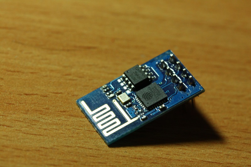
This modification has two derived GPIO ports, plus the UART_RX and UART_TX ports can be switched to GPIO mode. For my crafts, three GPIO ports are required: DATA and CLK for LPD6803 and a port for controlling the switch on / off of the entire tree.
For programming ESP8266, I decided to use a USB-UART converter on a PL2303 chip (which is easy to buy on ebay or aliexpress for a couple of dollars). This converter has four pins: + 5V, GND, RX, TX. The problem is that ESP8266 runs at 3.3V and 5V is not tolerant. For this reason (and just for convenience) I decided to do something similar to the development board for ESP8266:

This board lowers the voltage to 3.3V using the LM317 regulator, has pins for outputting GPIO, UART, GND, 3.3V, 5V and DIP switches for putting ESP8266 into firmware mode (GPIO0 to GND, GPIO2 to 3.3V).
Now a little about the implementation. The main part of the whole project is the driver for LPD6803. I ported it from the AdaFruit Arduino library. I will not talk about the principles of operation of the LPD6803 in this article, because material pulls on another article.
For those interested I will give some useful links:
- Datashit
- My code under ESP8266 on github.com
In my implementation, GPIO0 is used to connect to DATA LPD6803, and GPIO2 to CLK. For relyushki I needed to get another GPIO output. There were no dirty hacks to apply, so I just reassigned UART_RX to GPIO (still, my firmware doesn't support any input from the user). This line of code translates UART_RX to GPIO3:
PIN_FUNC_SELECT(PERIPHS_IO_MUX_U0RXD_U, FUNC_GPIO3); As a web server, I used the code from a friend of Sprite_tm. This web server, as far as I know, is used in almost all amateur projects on ESP8266. This web server already includes the functionality of connecting the device to the home network. By default, the device works in the access point mode. After connecting to this access point, the user can enter the browser at 10.10.10.1/wifi . On this page, he will be able to select the desired network for connection (if necessary, you can select a hidden network and specify a password). All web server responses can be obtained in JSON format, which is very convenient for integration into various systems and applications.
There is nothing more to tell me about the software part, the firmware code is available on github.com .
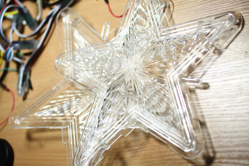
Now a little about the iron implementation. Let's start with the case. For him, I chose the old star, which once stood incandescent light bulbs. The body looks like this:
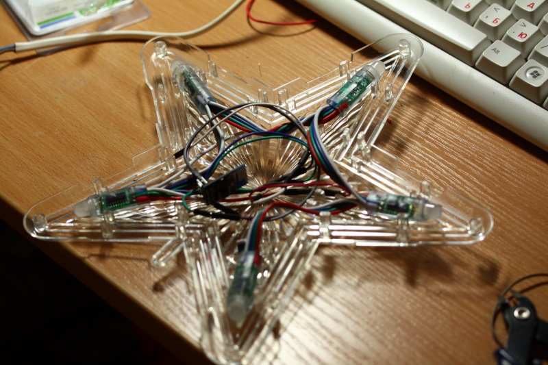
I was lucky, because RGB-LEDs with chips LPD6803 ideally stood in the clamps for incandescent lamps:
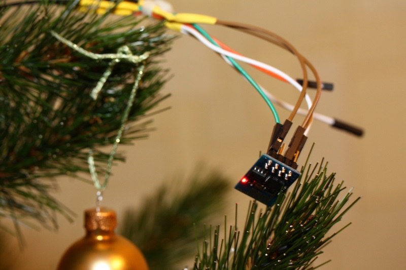
I decided to place the ESP8266 module directly in the star, since The quality of the Wi-Fi signal at the top of the tree will be better than under it.
Under the tree, I installed a 12V power supply and a self-made motherboard of this type:

As you can see, there are two voltage regulators on it, which give 5V and 3.3V. 5 volts is used LPD6803, and 3.3 volts, as already written above, ESP8266 eats. In addition to the regulators, there is a 12V relyushka on the board. Twitches through the transistor. From the box under the tree to the star goes 4-core cable: 3.3V, 5V, GND and relay control channel.
At the moment, there is a problem in the work of this star related to the bug in the TCP \ IP wrapper of the ESP8266 stack.
To solve this problem, you need to switch to the direct use of lwip without a wrapper.
There are two things in the development plans of the project:
1. Implement the work through the MQTT protocol;
2. Make a star with OpenHab .
And finally, video work. For management, the Android application is used (raw, so I do not post the source code). Voiced by wife:
Source: https://habr.com/ru/post/249643/
All Articles