STM32 and FreeRTOS. 4. Step toward HAL
HAL 9000: I'm perfectly functioning.or it should be the first article, but for some reason I always write like this near the end
It used to be about threads , semaphores and queues
 One of the main obstacles to the transition to the STM32 is the abundance of texts, instructions and manuals describing the work with the controller. The culprit for this abundance was STMicroelectronics itself, which initially systematically confused its users, and then offered the wrong exit options.
')
The problem lies in the variety of manufactured controllers, which for some reason required different initialization procedures even for the same periphery. And the code running on one controller refused to work on another. As a result, collections of shamanic recipes are walking around the network, which require a lot of time to burn and datasheets to burn.
But not so long ago, ST realized what pit she had fallen into and began to get out of her strenuously, attracting new forces. And precisely because of this, now the start time has been reduced to awkwardly small quantities. How does it look in practice? Welcome under cat.
To begin with, I will give advice on how to quickly determine what you should not read about STM32.
First, the year of publication earlier than 2011-2012. Just believe that "what then" and "what is now" are two big differences. SPL and HAL in the world of STM are not just regular abbreviations.
Secondly, if such a code is encountered (this is just a piece of ADC initialization, if anyone is interested).
RCC->APB2ENR |= RCC_APB2ENR_ADC1EN; ADC1->SMPR2 |= ADC_SMPR2_SMP0 | ADC_SMPR2_SMP1 | ADC_SMPR2_SMP2 | ADC_SMPR2_SMP3 | ADC_SMPR2_SMP4 | ADC_SMPR2_SMP5 | ADC_SMPR2_SMP6 | ADC_SMPR2_SMP7; ADC1->SQR1 |= ADC_SQR1_L_2 | ADC_SQR1_L_1 | ADC_SQR1_L_0; ADC1->SQR2 |= ADC_SQR2_SQ8_2 | ADC_SQR2_SQ8_1 | ADC_SQR2_SQ8_0 | ADC_SQR2_SQ7_2 | ADC_SQR2_SQ7_1; As a result, after watching this ... magnificence, most with the words “yes, it’s nafig, I’ll live with pinMode somehow, what to do with this” threw the board bought just in case into the far corner of the desk drawer. I will not hide, I myself was the same and only a great need made me study what is hidden behind the abbreviations CMSIS and SPL. There is absolutely no point in repeating my path now (and I tried to forget most of what I read), except if you have a very strong desire to get to the giblets. So here I am telling for those who need to go.
So what's the problem? The main and only problem is the initialization of the periphery. There those shamanic dances with bats did not appear from scratch. And 99% of the problems “it doesn't work for me” are precisely in the wrong initialization. Not those frequencies, an attempt to use the allocated resources, and so on and so forth. What particularly exacerbates the problem is that there are no error codes or there are no errors. Everything is like a sapper: he did something wrong - everything is dead.
It seems to you that this is a fairy tale? Here is a drawing of the STMF3 clocking scheme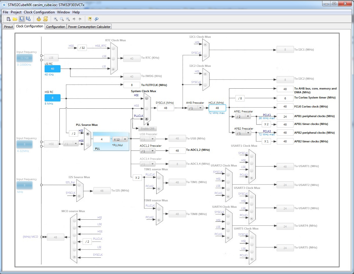
Counting the places where you can make a mistake, I suggest to do yourself
Counting the places where you can make a mistake, I suggest to do yourself
As a result, ST rolled out first SPL (Standard Peripheral Library), which at least improved the situation, but not much. And then the next version appeared, called HAL. And in order to make life even easier for developers, the STM32CubeMX utility was updated, which allowed just a couple of mouse clicks to generate initialization code for the whole variety of motherboards, processors and peripherals. And next to it put the so-called firmware, which shoved a bunch of examples of work for this processor.
And the fact that by pressing two buttons you can get 100% (I have never met the opposite), the working code absolutely presses the thought “there to optimize and optimize” ...
 The program itself is built on the familiar principle of all "choose the mouse what you need and press the button." I chose one clocking scheme - the program immediately showed frequencies and highlighted in red those places that cannot work with such frequencies. We tried to use the functionality that is impossible in these conditions (for example, the leg is already occupied by something else) - it will highlight the error again.
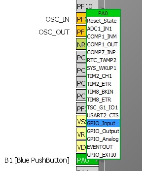
Here in the picture on the left, I showed a list of functions that can be hung on a single leg. After counting, usually AVRs (where 4 functions per leg are maximum) are long hacked and something is counted in the mind. And when I say to them that there may be more than 160 of these legs, they generally precipitate.
But what pleases me most is the fact that now, thanks to HAL, it is not necessary to rewrite the code for working with peripherals. If it is written somewhere
AL_GPIO_WritePin(GPIOA,GPIO_PIN_2,GPIO_PIN_RESET); I know that on all the processors currently available to me, this code will translate the leg of PA2 to “zero”. And even the written function of taking the average value of the desired ADC channel will also not resist during the transition from L1 to F4
int GetADCValue(uint32_t Channel,uint32_t Count) { int val = 0; ADC_ChannelConfTypeDef sConfig; sConfig.Channel=Channel; sConfig.Rank=1; sConfig.SamplingTime=10; HAL_ADC_ConfigChannel(&hadc,&sConfig); for(int i = 0; i < Count; i++) { HAL_ADC_Start(&hadc); HAL_ADC_PollForConversion(&hadc,1); val += HAL_ADC_GetValue(&hadc); } return val / Count; } And now a little put by the canons of magic STM32
What do you think, how much will I have to put in to get a com port from usb from STM32F3, which will simply return what was sent to it? I calculated here - 12 mouse clicks (enable USB, select CDC, generate) and 6 lines of code in the function CDC_Receive_FS (file usbd_cdc_if.c)
for (int i = 0; i < *Len; i++) UserTxBufferFS[i] = UserRxBufferFS[i]; USBD_CDC_SetTxBuffer(&hUsbDeviceFS, &UserTxBufferFS[0], *Len); USBD_CDC_TransmitPacket(&hUsbDeviceFS); USBD_CDC_SetRxBuffer(&hUsbDeviceFS, &UserRxBufferFS[0]); USBD_CDC_ReceivePacket(&hUsbDeviceFS); And about the same complexity and with the same complexity implemented "sound card", "flash drive" or HID. Yes, they will give only initialization code, it will be necessary to write the logic yourself, but this is an awesome help.
I will not even lay out the project, for I’m trying to drag you to something that I hope you already have on your computer, but I’ll show you the result.

The answer to the question “where can I take a sample?” Is simple: there are a lot of examples in the downloaded firmware. And I recommend to pump up (in the menu you will find) the “firmware” for other processor models - very often the examples do not overlap and the same “ADC via DMA” is only in one place, although it works fine there and there.
In a separate paragraph, I note that although the STM32Cube helps the programmer in a quick start, it still requires an understanding of what is being configured and why it is being so configured. For example, by default, interrupts and DMA for USART are disabled, so some functions simply will not work. In general, carefully look for the tabs, the benefit of the program allows you to regenerate the project, keeping the already written.
Somewhere around here, programmers usually have to go into the generation of “something like that”, change descriptors, buffer sizes and change the displayed name in the task manager to “Super Cool Device”. Well, I'll leave you with this.
We are completing and benefiting
Source: https://habr.com/ru/post/249395/
All Articles