A brief course of computer graphics: we write a simplified OpenGL do it yourself, article 5 of 6
Content of the main course
- Article 1: Bresenham algorithm
- Article 2: rasterization of the triangle + clipping of the rear faces
- Article 3: Removing invisible surfaces: z-buffer
- Article 4: Required Geometry: Matrix Festival
- Article 5: We write shaders for our library
- Article 6: A little more than just a shader: shadow rendering
Code enhancement
The official translation (with a bit of polishing) is available here.
')
It's time for fun, let's first look at the size of the current code :
- geometry.cpp + .h - 218 lines
- model.cpp + .h - 139 lines
- our_gl.cpp + .h - 102 lines
- main.cpp - 66 lines
A total of 525 lines . Exactly what I promised at the very beginning of the course. And note that we are engaged in rendering only in our_gl and main, which is only 168 lines, and nowhere have we called third-party libraries, we have done all the drawing from scratch!
I remind you that my code is needed only for the final comparison with your working code! In an amicable way, you should write everything from scratch if you follow this series of articles. I beg you, make the craziest shaders and post pictures in the comments !!!
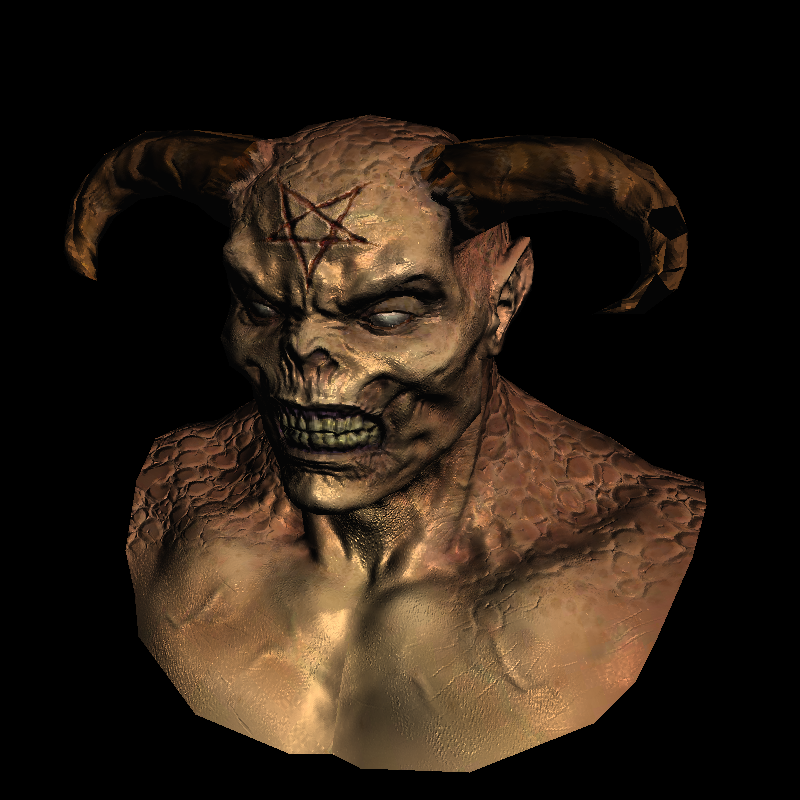
The black triangles on the horns are a slightly broken model, I just tired of the head of the old Negro, but I don’t want to fix it.
Refactor our code to look like the OpenGL structure
So, our main.cpp starts to grow slightly, so let's divide it into two parts
- our_gl.cpp + .h is a part that we cannot program, roughly speaking, a binary library file.
- main.cpp - here we can program what we want.
Let's take a look at what I brought to our_gl ? The functions of constructing matrices of projection, type and transition to screen coordinates, as well as the matrices themselves, are simply global variables. Well, the triangle rasterizer function. Everything!
Here is the contents of the file our_gl.h (about the appointment of IShader later):
#include "tgaimage.h" #include "geometry.h" extern Matrix ModelView; extern Matrix Viewport; extern Matrix Projection; void viewport(int x, int y, int w, int h); void projection(float coeff=0.f); // coeff = -1/c void lookat(Vec3f eye, Vec3f center, Vec3f up); struct IShader { virtual ~IShader(); virtual Vec3i vertex(int iface, int nthvert) = 0; virtual bool fragment(Vec3f bar, TGAColor &color) = 0; }; void triangle(Vec4f *pts, IShader &shader, TGAImage &image, TGAImage &zbuffer); There are only 66 lines left in the main.cpp file , so I give it entirely (sorry for the sheet, but I like this file so much that I won't hide it under the spoiler):
#include <vector> #include <iostream> #include "tgaimage.h" #include "model.h" #include "geometry.h" #include "our_gl.h" Model *model = NULL; const int width = 800; const int height = 800; Vec3f light_dir(1,1,1); Vec3f eye(1,1,3); Vec3f center(0,0,0); Vec3f up(0,1,0); struct GouraudShader : public IShader { Vec3f varying_intensity; // written by vertex shader, read by fragment shader virtual Vec4f vertex(int iface, int nthvert) { varying_intensity[nthvert] = std::max(0.f, model->normal(iface, nthvert)*light_dir); // get diffuse lighting intensity Vec4f gl_Vertex = embed<4>(model->vert(iface, nthvert)); // read the vertex from .obj file return Viewport*Projection*ModelView*gl_Vertex; // transform it to screen coordinates } virtual bool fragment(Vec3f bar, TGAColor &color) { float intensity = varying_intensity*bar; // interpolate intensity for the current pixel color = TGAColor(255, 255, 255)*intensity; // well duh return false; // no, we do not discard this pixel } }; int main(int argc, char** argv) { if (2==argc) { model = new Model(argv[1]); } else { model = new Model("obj/african_head.obj"); } lookat(eye, center, up); viewport(width/8, height/8, width*3/4, height*3/4); projection(-1.f/(eye-center).norm()); light_dir.normalize(); TGAImage image (width, height, TGAImage::RGB); TGAImage zbuffer(width, height, TGAImage::GRAYSCALE); GouraudShader shader; for (int i=0; i<model->nfaces(); i++) { Vec4f screen_coords[3]; for (int j=0; j<3; j++) { screen_coords[j] = shader.vertex(i, j); } triangle(screen_coords, shader, image, zbuffer); } image. flip_vertically(); // to place the origin in the bottom left corner of the image zbuffer.flip_vertically(); image. write_tga_file("output.tga"); zbuffer.write_tga_file("zbuffer.tga"); delete model; return 0; } Let's analyze it in detail. Headings are skipped, then global constants follow: screen sizes, where the camera is located, etc.
The structure of GouraudShader will be analyzed in the next paragraph, skipping. Then it goes directly to main ():
- Reading a model from an .obj file
- Initialization of the matrices ModelView, Projection and Viewport (remember, the variables themselves are stored in our_gl module)
- Passing through the model and drawing it
The last point begins the most interesting. The outer loop passes through all triangles.
The inner loop passes through all the vertices of the triangle and for each of them calls the vertex shader.
The main purpose of the vertex shader is to calculate the transformed vertex coordinates. The secondary is to prepare data for the operation of the fragment shader.
What happens after we call the vertex shader for all the vertices in the triangle? We can call the rasterizer of our triangle. What happens inside it we do not know (no, well, we wrote it ourselves, of course). Except for one interesting thing. The triangle rasterizer calls our function, which we give it — the fragment shader. That is, once again, for each pixel inside the triangle, the rasterizer calls a fragment shader.
The main purpose of the fragment shader is to determine the color of the current pixel. Secondary - we can refuse to paint at all this pixel, returning true.
OpenGL 2 Pipeline looks like this:
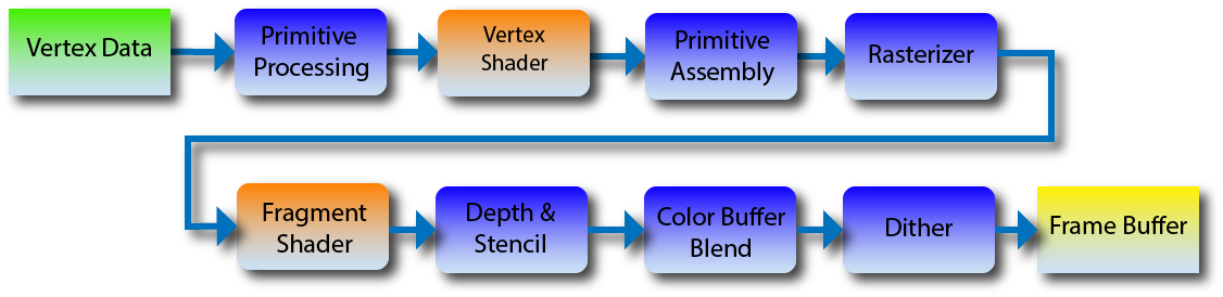
Since we have a short course of graphics, for now let's restrict ourselves to these two shaders. In newer versions of OpenGL, new types of shaders have appeared that allow you to create geometry on the fly. In this picture in blue shows the stages that we can not program, and the red are those that we can. In fact, our main () is primitive processing. She calls the vertex shader. We do not have a collector of primitives, because we draw blunt triangles directly (it stuck together with primitive processing). The triangle () function is a rasterizer, for each point it calls a fragment shader and then does depth checks in the z-buffer, and so on.
Everything. You know what shaders are and you can start programming them.
How does my embodiment of shaders work on the example of tinting Guro
Let's analyze those shaders that I brought in the code main.cpp . As you might guess, the first shader is the toning of Guro.
Hidden text
The vertex shader reads the vertex from the .obj file, plunges it into four-dimensional space (see previous article), finds its screen coordinates. Returns a projected 3D point, but before that it considers the diffuse luminance coefficient for a given vertex and saves it to the corresponding component of the varying_intensity vector.
Once again, the code for convenience:
Hidden text
Vec3f varying_intensity; // written by vertex shader, read by fragment shader virtual Vec4f vertex(int iface, int nthvert) { varying_intensity[nthvert] = std::max(0.f, model->normal(iface, nthvert)*light_dir); // get diffuse lighting intensity Vec4f gl_Vertex = embed<4>(model->vert(iface, nthvert)); // read the vertex from .obj file return Viewport*Projection*ModelView*gl_Vertex; // transform it to screen coordinates } varying is a reserved word in the GLSL language, I used varying_intensity as the name just to emphasize the parallel between them (we'll talk about GLSL in the seventh article). We save in the varying structure the data that will be interpolated inside the triangle, and the fragment shader will receive the already interpolated data.
Let's analyze the fragment shader, once again the code for convenience:
Hidden text
Vec3f varying_intensity; // written by vertex shader, read by fragment shader // [...] virtual bool fragment(Vec3f bar, TGAColor &color) { float intensity = varying_intensity*bar; // interpolate intensity for the current pixel color = TGAColor(255, 255, 255)*intensity; // well duh return false; // no, we do not discard this pixel } It is called a rasterizer for each pixel inside the triangle. It takes as input barycentric coordinates for interpolating varying_ data.
That is, the interpolated intensity can be calculated as varying_intensity [0] * bar [0] + varying_intensity [1] * bar [1] + varying_intensity [2] * bar [2] or simply the scalar product between the varying_intensity vectors * bar. In the present GLSL, of course, the shader gets a ready-made value.
Note that the fragment shader returns a boolean value. Its value is easy to understand if you look inside the rasterizer ( our_gl.cpp , triangle ()):
Hidden text
TGAColor color; bool discard = shader.fragment(c, color); if (!discard) { zbuffer.set(Px, Py, TGAColor(Pz)); image.set(Px, Py, color); } The shader may refuse to draw this pixel, then the rasterizer ignores its z-coordinate without updating the z-buffer. Useful if we want to do binary masks or whatever else comes to your head.
Of course, the rasterizer cannot even come up with what comes into your head, so it cannot compile with your shader in advance. This is where the abstract class IShader comes to the rescue. Uff, infrequently I use abstract classes, but there is exactly a case when it would be bad without him. I don't want to pass pointers to functions at all!
First modification
Hidden text
virtual bool fragment(Vec3f bar, TGAColor &color) { float intensity = varying_intensity*bar; if (intensity>.85) intensity = 1; else if (intensity>.60) intensity = .80; else if (intensity>.45) intensity = .60; else if (intensity>.30) intensity = .45; else if (intensity>.15) intensity = .30; else intensity = 0; color = TGAColor(255, 155, 0)*intensity; return false; } I just allow some fixed set of light intensities. Here is the result of his work:
Hidden text
Texture model
Phong's tinted skip, it was disassembled in detail in the comments, let's apply textures. To do this, you have to interpol the uv-coordinates. Nothing new, just add the matrix in two rows (uv) and three columns (texture coordinates of three vertices).
Hidden text
struct Shader : public IShader { Vec3f varying_intensity; // written by vertex shader, read by fragment shader mat<2,3,float> varying_uv; // same as above virtual Vec4f vertex(int iface, int nthvert) { varying_uv.set_col(nthvert, model->uv(iface, nthvert)); varying_intensity[nthvert] = std::max(0.f, model->normal(iface, nthvert)*light_dir); // get diffuse lighting intensity Vec4f gl_Vertex = embed<4>(model->vert(iface, nthvert)); // read the vertex from .obj file return Viewport*Projection*ModelView*gl_Vertex; // transform it to screen coordinates } virtual bool fragment(Vec3f bar, TGAColor &color) { float intensity = varying_intensity*bar; // interpolate intensity for the current pixel Vec2f uv = varying_uv*bar; // interpolate uv for the current pixel color = model->diffuse(uv)*intensity; // well duh return false; // no, we do not discard this pixel } }; Hidden text
Normalmapping
Okay, now we have texture coordinates. But after all, not only color can be stored in textures, RGB is enough to represent xyz!
Let's load this texture, which for each pixel of our image (and not just for the vertices, as before!) Will give a normal vector.
Hidden text
By the way, compare it with such a picture, this is the same information, but in a different reference:
Hidden text
One of these pictures gives normal vectors in the global coordinate system, and the other in the tangent, which is defined for each point of our object. In this texture, the vector z is the normal to the object, the vector x is the vector of the main direction of curvature of the surface, and y is their vectorial product.
Exercise 1
Tell me, which of these textures is given in global coordinates, and which in tangents to the object?Exercise 2
Which texture format is preferred - tangent or global? Why?Please do not hesitate (without reading the comments in advance) to give answers to these questions in the comments!
Hidden text
struct Shader : public IShader { mat<2,3,float> varying_uv; // same as above mat<4,4,float> uniform_M; // Projection*ModelView mat<4,4,float> uniform_MIT; // (Projection*ModelView).invert_transpose() virtual Vec4f vertex(int iface, int nthvert) { varying_uv.set_col(nthvert, model->uv(iface, nthvert)); Vec4f gl_Vertex = embed<4>(model->vert(iface, nthvert)); // read the vertex from .obj file return Viewport*Projection*ModelView*gl_Vertex; // transform it to screen coordinates } virtual bool fragment(Vec3f bar, TGAColor &color) { Vec2f uv = varying_uv*bar; // interpolate uv for the current pixel Vec3f n = proj<3>(uniform_MIT*embed<4>(model->normal(uv))).normalize(); Vec3f l = proj<3>(uniform_M *embed<4>(light_dir )).normalize(); float intensity = std::max(0.f, n*l); color = model->diffuse(uv)*intensity; // well duh return false; // no, we do not discard this pixel } }; [...] Shader shader; shader.uniform_M = Projection*ModelView; shader.uniform_MIT = (Projection*ModelView).invert_transpose(); for (int i=0; i<model->nfaces(); i++) { Vec4f screen_coords[3]; for (int j=0; j<3; j++) { screen_coords[j] = shader.vertex(i, j); } triangle(screen_coords, shader, image, zbuffer); } The uniform keyword in GLSL allows you to transfer constants to shaders, here I passed the Projection * Modelview matrix and its reverse transposed to the shader in order to transform normal vectors (see previous article).
That is, everything is the same as before, only we do not interpolate the normal vector, but take it from the prepared texture, while not forgetting to transform the vector of the direction of light and the normal vector properly.
Hidden text
Shiny surfaces or specular mapping
We continue the conversation! For the (cheap) deception of the eye, we use the Phong approximation to illuminate the model. The total luminosity of this area is made up of constant illumination for the whole scene (ambient lighting), illumination for matte surfaces, which we have considered so far (diffuse lighting) and illumination for glossy surfaces (specular lighting):

We considered matte surfaces as the cosine of the angle between the normal vector and the light vector. That is, we assumed that the surface scatters light in approximately all directions. What happens to glossy surfaces? In the limiting case (for mirror surfaces) we have light if we see a source of light from this pixel.
Here is a picture:

If for a given point we considered illumination for matte surfaces as the cosine of the angle between the vectors n and l , then now we are interested in the cosine of the angle between the vectors r (reflected light) and v (direction of gaze).
Exercise 3: find the vector r, having vectors n and l
Hidden text
if n and l are normalized, then r = 2 n < n , l > - l
I remind you that we considered the light for a matte surface as the cosine of an angle. But the glossy reflects the source in a much more focused beam! What will happen if we do the same, only we will raise this cosine to the tenth power? I remind you that the numbers less than one in the tenth degree will decrease in relation to themselves! That is, the tenth degree will give a significantly smaller radius of light. And the hundredth is even smaller. This degree is stored in a texture that gives glossiness for each point of the surface.
Hidden text
struct Shader : public IShader { mat<2,3,float> varying_uv; // same as above mat<4,4,float> uniform_M; // Projection*ModelView mat<4,4,float> uniform_MIT; // (Projection*ModelView).invert_transpose() virtual Vec4f vertex(int iface, int nthvert) { varying_uv.set_col(nthvert, model->uv(iface, nthvert)); Vec4f gl_Vertex = embed<4>(model->vert(iface, nthvert)); // read the vertex from .obj file return Viewport*Projection*ModelView*gl_Vertex; // transform it to screen coordinates } virtual bool fragment(Vec3f bar, TGAColor &color) { Vec2f uv = varying_uv*bar; Vec3f n = proj<3>(uniform_MIT*embed<4>(model->normal(uv))).normalize(); Vec3f l = proj<3>(uniform_M *embed<4>(light_dir )).normalize(); Vec3f r = (n*(n*l*2.f) - l).normalize(); // reflected light float spec = pow(std::max(rz, 0.0f), model->specular(uv)); float diff = std::max(0.f, n*l); TGAColor c = model->diffuse(uv); color = c; for (int i=0; i<3; i++) color[i] = std::min<float>(5 + c[i]*(diff + .6*spec), 255); return false; } }; Actually, there is nothing to explain here, except for the coefficients. In line
for (int i = 0; i <3; i ++) color [i] = std :: min <float> (5 + c [i] * (diff + .6 * spec), 255);
I took 5 for ambient, 1 for diffuse and .6 for specular. What exactly to take - you decide. This gives the impression of different materials. Most often they are given by the artist, but in this case I don’t have them, so I took about from the bald.
Hidden text
Conclusion
We have learned how to render very realistic scenes, but the lighting is still far from ideal. In the next article I will talk about what shadow mapping is. In one of the orthogonal articles, I will talk about how the new rasterizer works (nothing prevents you from running the same code on the old rasterizer!).
Source: https://habr.com/ru/post/248963/
All Articles