Arduino do-it-yourself soldering station
Hello! Somehow I touched on the topic of the soldering station on the Arduino and immediately filled me up with questions (how / where / when). Given the massive demands, I decided to write an overview of a simple soldering station (soldering iron only) based on Arduino.
Why Arduino? After all, there is a lot of controllers faster and cheaper. In such cases, I usually answer: - Cheap, practical, fast.
Indeed, after all, the Arduino Pro Mini is now worth $ 1.63 for 1 piece (recently sent), and atmega8 costs $ 1 (wholesale price). It turns out that the Pro Mini board with a body kit (quartz, capacitors, stabilizers) is not so expensive, plus it saves time. Also, the IDE-shell for Arduino saves time very much, even a schoolboy can easily and quickly cope with it. Given the popularity and cheapness, I decided to build it on the Arduino.
To create a soldering station, we first need the handle of the soldering station, often they are Chinese stations of type 907 A1322 939.
')

Let's start
Handle characteristics:
Voltage: 24V DC
Power: 50W (60W)
Temperature: 200 ~ 480 ℃
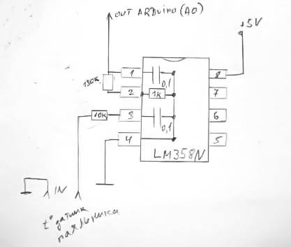
To control the soldering iron handle, we first need to remove the data from the temperature sensor, LM358N will help us in this. This scheme has been working for me for almost 2 years.
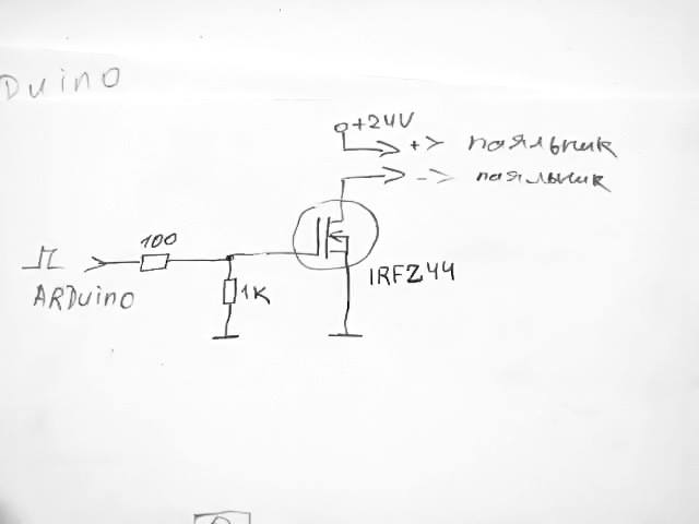
Next we need to control (turn on and off) the heating element of the soldering iron, this will help the pulse transistor IRFZ44 . Its connection is very simple:
I want to draw your attention to the future mode of operation of the heating element. We will include it in three stages by PWM modulation. When the program starts, almost the maximum power will turn on (90% duty cycle), when approaching a given temperature, the power decreases (35-45% duty cycle), and with a minimum difference between the current and set temperature, the power is kept to a minimum (30-35% duty cycle). Thus, we eliminate the inertia of overheating. I repeat, the soldering station has been working stably for almost 2 years, and the thermoelement is not in constant maximum load (which prolongs its life). All settings in the program can be edited.
It is necessary to connect the handle according to the scheme:

Note the connector on the station panel, not on the handle.
I insist very much : check the knobs before starting, unwind and check the integrity of the heating element, as well as the correctness of the wire soldering on the connector.
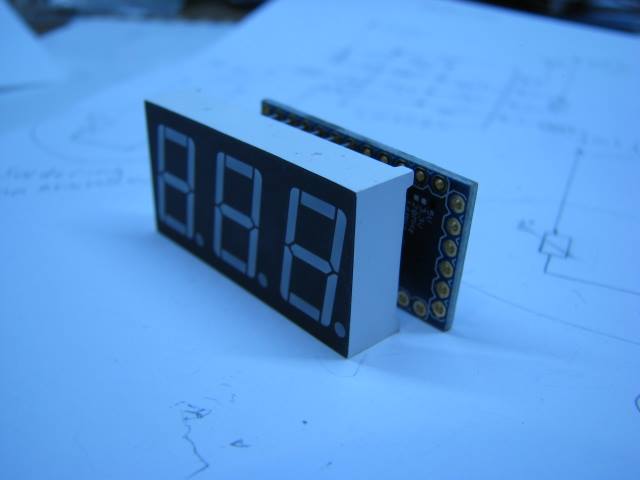
Next we need a controller. For the demonstration, I chose the Arduino Uno - as the most popular and convenient. Note that I make a soldering station with a block station and this makes it possible to choose the controller myself. We also need two buttons tightened to + 5V resistances of 10kOhm and a 7-segment indicator for three digits. I connected the pins of the segments through a resistance of 100 ohms.
ANODES:
D0 - a
D1 - b
D2 - c
D3 - d
D4 - e
D5 - f
D6 - g
D7 - dp (dot)
CATHODES:
D8 - cathode 3
D9 - cathode 2
D10 - cathode 1
I would also like to note that we put the buttons on analog pins 3 and 2. And in the program I will interrogate them as an analog. I did this in order not to mislead the younger generation. Not everyone knows where to find pin 14, 15 and 16. And considering that there is enough speed and a lot of memory in the controller, then it will be easier.
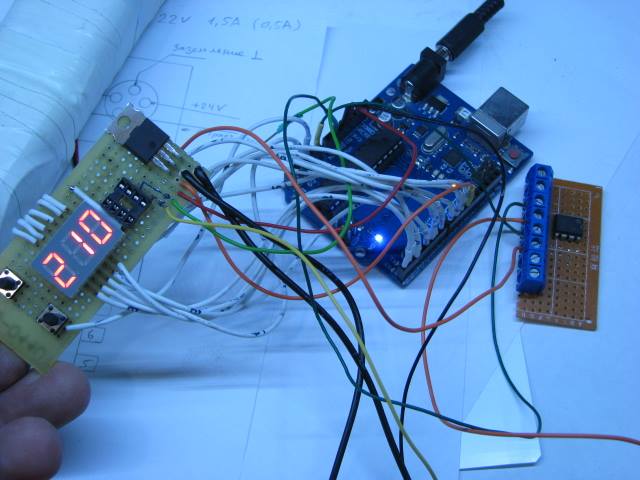
Let's see what happened:
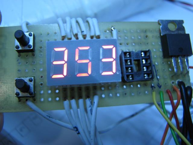
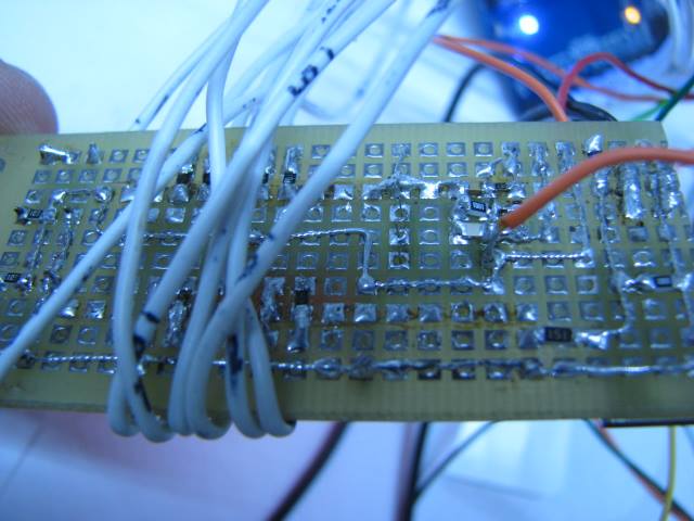
You may notice an empty panel near the indicator, this is a blank for LM358N, just an analogue of the KA358 showed poor results. Therefore, I used the block of thermal sensors on the LM358N for the soldering station with a hairdryer.


Next you need to choose a power source. I took the power supply from some laptop on 22V 3A, it is enough with a margin. The consumption at the start of the soldering iron is 1.5 A and with the temperature being maintained at 0.5A. Therefore, choose a suitable power supply, preferably 24V DC 2A.
In the photo above you can see tight wires and it scares many. Understand, this is a demo, an option for any controller, the station can be assembled and compact, for example:

This is a good example for your soldering station project. A video that clearly helps you understand how to build yourself:
Here is the test program, wrote under the version of IDE 1.5.2. Consider the above and do not criticize much (the program tried to write simply and affordably).
I really hope that this will somehow help you in creating your project.
Why Arduino? After all, there is a lot of controllers faster and cheaper. In such cases, I usually answer: - Cheap, practical, fast.
Indeed, after all, the Arduino Pro Mini is now worth $ 1.63 for 1 piece (recently sent), and atmega8 costs $ 1 (wholesale price). It turns out that the Pro Mini board with a body kit (quartz, capacitors, stabilizers) is not so expensive, plus it saves time. Also, the IDE-shell for Arduino saves time very much, even a schoolboy can easily and quickly cope with it. Given the popularity and cheapness, I decided to build it on the Arduino.
To create a soldering station, we first need the handle of the soldering station, often they are Chinese stations of type 907 A1322 939.
')
Let's start
Handle characteristics:
Voltage: 24V DC
Power: 50W (60W)
Temperature: 200 ~ 480 ℃
To control the soldering iron handle, we first need to remove the data from the temperature sensor, LM358N will help us in this. This scheme has been working for me for almost 2 years.
Next we need to control (turn on and off) the heating element of the soldering iron, this will help the pulse transistor IRFZ44 . Its connection is very simple:
I want to draw your attention to the future mode of operation of the heating element. We will include it in three stages by PWM modulation. When the program starts, almost the maximum power will turn on (90% duty cycle), when approaching a given temperature, the power decreases (35-45% duty cycle), and with a minimum difference between the current and set temperature, the power is kept to a minimum (30-35% duty cycle). Thus, we eliminate the inertia of overheating. I repeat, the soldering station has been working stably for almost 2 years, and the thermoelement is not in constant maximum load (which prolongs its life). All settings in the program can be edited.
It is necessary to connect the handle according to the scheme:
Note the connector on the station panel, not on the handle.
I insist very much : check the knobs before starting, unwind and check the integrity of the heating element, as well as the correctness of the wire soldering on the connector.
Next we need a controller. For the demonstration, I chose the Arduino Uno - as the most popular and convenient. Note that I make a soldering station with a block station and this makes it possible to choose the controller myself. We also need two buttons tightened to + 5V resistances of 10kOhm and a 7-segment indicator for three digits. I connected the pins of the segments through a resistance of 100 ohms.
ANODES:
D0 - a
D1 - b
D2 - c
D3 - d
D4 - e
D5 - f
D6 - g
D7 - dp (dot)
CATHODES:
D8 - cathode 3
D9 - cathode 2
D10 - cathode 1
I would also like to note that we put the buttons on analog pins 3 and 2. And in the program I will interrogate them as an analog. I did this in order not to mislead the younger generation. Not everyone knows where to find pin 14, 15 and 16. And considering that there is enough speed and a lot of memory in the controller, then it will be easier.
Let's see what happened:
You may notice an empty panel near the indicator, this is a blank for LM358N, just an analogue of the KA358 showed poor results. Therefore, I used the block of thermal sensors on the LM358N for the soldering station with a hairdryer.
Next you need to choose a power source. I took the power supply from some laptop on 22V 3A, it is enough with a margin. The consumption at the start of the soldering iron is 1.5 A and with the temperature being maintained at 0.5A. Therefore, choose a suitable power supply, preferably 24V DC 2A.
In the photo above you can see tight wires and it scares many. Understand, this is a demo, an option for any controller, the station can be assembled and compact, for example:
This is a good example for your soldering station project. A video that clearly helps you understand how to build yourself:
Here is the test program, wrote under the version of IDE 1.5.2. Consider the above and do not criticize much (the program tried to write simply and affordably).
/* // ANODES: D0 - a D1 - b D2 - c D3 - d D4 - e D5 - f D6 - g D7 - dp (digital point) a ******** * * f * * b * g * ******** * * e * * c * d * ******** # dp CATHODES: D8 - cathode 3 D9 - cathode 2 D10 - cathode 1 */ // -------------------------------------------------- , ----------------------------------------------- byte const digits[] = { B00111111,B00000110,B01011011,B01001111,B01100110,B01101101,B01111101,B00000111,B01111111,B01101111}; int digit_common_pins[]={8,9,10}; // ( ) int refresh_delay = 5; int count_delay = 300; // COUNTING SECONDS IF count_delay = 1000 long actual_count_delay = 0; long actual_refresh_delay = 0; int increment = 0; // int max_digits =3; // - int current_digit=max_digits-1; int increment_max = pow(10,max_digits); // -------------------------------------------------- , ----------------------------------------------- //--------------------- ----------------------------- int knup = 3; // in( ) int kndn = 2; // in( ) int nagr = 11; // ( ) int tin = 0; // IN Analog LM358N int tdat = 0; // int ustt = 210; // (+ ) int mintemp = 140; // int maxtemp = 310; // int nshim = 0; // void setup(){ pinMode(nagr,OUTPUT); // () analogWrite(nagr, nshim); // ( 0 - - ) // -------------------------------------------------- , ----------------------------------------------- DDRD = B11111111; for (int y=0;y<max_digits;y++) { pinMode(digit_common_pins[y],OUTPUT); digitalWrite(digit_common_pins[y], HIGH); } // -------------------------------------------------- , ----------------------------------------------- } void loop() { show(increment); // (LED) if (tdat < ustt ){ // : if ((ustt - tdat) < 16 & (ustt - tdat) > 6 ) // , // 10 , { nshim = 99; // ( 0-255, 99) - } else if ((ustt - tdat) < 7 & (ustt - tdat) > 3) { nshim = 80; // ( 0-255, 99) - } else if ((ustt - tdat) < 4 ) { nshim = 45; // ( 0-255, 99) - } else { nshim = 230; // ( 0-255, 230) } analogWrite(nagr, nshim); // ( ) } else { // ( ) nshim = 0; // ( 0-255 0) - analogWrite(nagr, nshim); // ( ) } if(millis() - actual_count_delay > count_delay) // { actual_count_delay = millis(); // ( ) tdat = analogRead(tin); // tdat tdat =map(tdat,0,430,25,310); // 0,430,25,310 increment = tdat; // if (analogRead(kndn) < 1) // , 5 { if( ustt <= mintemp || (ustt-5) <= mintemp ) { ustt= mintemp; increment = ustt; } else { ustt=ustt-5; increment = ustt; } } else if (analogRead(knup) < 1) // , 5 { ustt=ustt+5; if( ustt >=maxtemp) { ustt= maxtemp; } increment = ustt; } } } void show(int value) { //------------------------------- - --------------------------------------------- int digits_array[]={}; int y=0; boolean empty_most_significant = true; if(millis() - actual_refresh_delay >= refresh_delay) { for (int z=max_digits-1;z>=0;z--) { digits_array[z] = value / pow(10,z); //rounding down by converting from float to int if(digits_array[z] != 0 ) empty_most_significant = false; // DON'T SHOW LEADING ZEROS value = value - digits_array[z] * pow(10,z); if(z==current_digit) { if(!empty_most_significant || z==0){ // DON'T SHOW LEADING ZEROS EXCEPT FOR THE LEAST SIGNIFICANT PORTD = digits[digits_array[z]]; } else { PORTD = B00000000; } digitalWrite(digit_common_pins[z], LOW); }else{ digitalWrite(digit_common_pins[z], HIGH); } } current_digit--; if(current_digit < 0) { current_digit= max_digits; // NEED AN EXTRA REFRESH CYCLE TO CLEAR ALL DIGITS } actual_refresh_delay = millis(); } } I really hope that this will somehow help you in creating your project.
Source: https://habr.com/ru/post/248959/
All Articles